EP0631090A2 - Brennstoffstrahlverbrennung mit kontrollierter Flamme - Google Patents
Brennstoffstrahlverbrennung mit kontrollierter Flamme Download PDFInfo
- Publication number
- EP0631090A2 EP0631090A2 EP94109581A EP94109581A EP0631090A2 EP 0631090 A2 EP0631090 A2 EP 0631090A2 EP 94109581 A EP94109581 A EP 94109581A EP 94109581 A EP94109581 A EP 94109581A EP 0631090 A2 EP0631090 A2 EP 0631090A2
- Authority
- EP
- European Patent Office
- Prior art keywords
- cavity
- fuel
- oxygen
- nozzle
- velocity
- Prior art date
- Legal status (The legal status is an assumption and is not a legal conclusion. Google has not performed a legal analysis and makes no representation as to the accuracy of the status listed.)
- Granted
Links
Images
Classifications
-
- F—MECHANICAL ENGINEERING; LIGHTING; HEATING; WEAPONS; BLASTING
- F23—COMBUSTION APPARATUS; COMBUSTION PROCESSES
- F23D—BURNERS
- F23D14/00—Burners for combustion of a gas, e.g. of a gas stored under pressure as a liquid
- F23D14/32—Burners for combustion of a gas, e.g. of a gas stored under pressure as a liquid using a mixture of gaseous fuel and pure oxygen or oxygen-enriched air
-
- F—MECHANICAL ENGINEERING; LIGHTING; HEATING; WEAPONS; BLASTING
- F23—COMBUSTION APPARATUS; COMBUSTION PROCESSES
- F23C—METHODS OR APPARATUS FOR COMBUSTION USING FLUID FUEL OR SOLID FUEL SUSPENDED IN A CARRIER GAS OR AIR
- F23C7/00—Combustion apparatus characterised by arrangements for air supply
- F23C7/02—Disposition of air supply not passing through burner
-
- F—MECHANICAL ENGINEERING; LIGHTING; HEATING; WEAPONS; BLASTING
- F23—COMBUSTION APPARATUS; COMBUSTION PROCESSES
- F23C—METHODS OR APPARATUS FOR COMBUSTION USING FLUID FUEL OR SOLID FUEL SUSPENDED IN A CARRIER GAS OR AIR
- F23C9/00—Combustion apparatus characterised by arrangements for returning combustion products or flue gases to the combustion chamber
- F23C9/006—Combustion apparatus characterised by arrangements for returning combustion products or flue gases to the combustion chamber the recirculation taking place in the combustion chamber
-
- F—MECHANICAL ENGINEERING; LIGHTING; HEATING; WEAPONS; BLASTING
- F23—COMBUSTION APPARATUS; COMBUSTION PROCESSES
- F23D—BURNERS
- F23D14/00—Burners for combustion of a gas, e.g. of a gas stored under pressure as a liquid
- F23D14/46—Details, e.g. noise reduction means
- F23D14/72—Safety devices, e.g. operative in case of failure of gas supply
- F23D14/76—Protecting flame and burner parts
-
- F—MECHANICAL ENGINEERING; LIGHTING; HEATING; WEAPONS; BLASTING
- F23—COMBUSTION APPARATUS; COMBUSTION PROCESSES
- F23L—SUPPLYING AIR OR NON-COMBUSTIBLE LIQUIDS OR GASES TO COMBUSTION APPARATUS IN GENERAL ; VALVES OR DAMPERS SPECIALLY ADAPTED FOR CONTROLLING AIR SUPPLY OR DRAUGHT IN COMBUSTION APPARATUS; INDUCING DRAUGHT IN COMBUSTION APPARATUS; TOPS FOR CHIMNEYS OR VENTILATING SHAFTS; TERMINALS FOR FLUES
- F23L7/00—Supplying non-combustible liquids or gases, other than air, to the fire, e.g. oxygen, steam
- F23L7/007—Supplying oxygen or oxygen-enriched air
-
- F—MECHANICAL ENGINEERING; LIGHTING; HEATING; WEAPONS; BLASTING
- F23—COMBUSTION APPARATUS; COMBUSTION PROCESSES
- F23L—SUPPLYING AIR OR NON-COMBUSTIBLE LIQUIDS OR GASES TO COMBUSTION APPARATUS IN GENERAL ; VALVES OR DAMPERS SPECIALLY ADAPTED FOR CONTROLLING AIR SUPPLY OR DRAUGHT IN COMBUSTION APPARATUS; INDUCING DRAUGHT IN COMBUSTION APPARATUS; TOPS FOR CHIMNEYS OR VENTILATING SHAFTS; TERMINALS FOR FLUES
- F23L2900/00—Special arrangements for supplying or treating air or oxidant for combustion; Injecting inert gas, water or steam into the combustion chamber
- F23L2900/07005—Injecting pure oxygen or oxygen enriched air
-
- Y—GENERAL TAGGING OF NEW TECHNOLOGICAL DEVELOPMENTS; GENERAL TAGGING OF CROSS-SECTIONAL TECHNOLOGIES SPANNING OVER SEVERAL SECTIONS OF THE IPC; TECHNICAL SUBJECTS COVERED BY FORMER USPC CROSS-REFERENCE ART COLLECTIONS [XRACs] AND DIGESTS
- Y02—TECHNOLOGIES OR APPLICATIONS FOR MITIGATION OR ADAPTATION AGAINST CLIMATE CHANGE
- Y02E—REDUCTION OF GREENHOUSE GAS [GHG] EMISSIONS, RELATED TO ENERGY GENERATION, TRANSMISSION OR DISTRIBUTION
- Y02E20/00—Combustion technologies with mitigation potential
- Y02E20/34—Indirect CO2mitigation, i.e. by acting on non CO2directly related matters of the process, e.g. pre-heating or heat recovery
Definitions
- This invention relates to methods and apparatus for carrying out combustion in conjunction with a high temperature combustion zone.
- High temperature combustion is often employed in many industrial processes such as in glassmelting. Corrosion and fouling of burner nozzles are common problems in high temperature industrial processes. Water cooling of metallic nozzles is often used to prevent high temperature corrosion or melting. Although water cooling is effective in a relatively clean furnace atmosphere, it adds to the complexity of the combustion system and also could escalate the corrosion and fouling problem when the furnace atmosphere contains condensible vapors. Ceramic nozzles have been proposed for use with high temperature combustion as a way for avoiding water cooling. However, presently available ceramic nozzles tend to develop cracks due to thermal and other stresses and are not considered dependable for many industrial applications. The problem of designing a non-water cooled burner is particularly severe where the burner employs oxygen or oxygen-enriched air rather than air as the oxidant because of the high flame temperature generated.
- High temperature combustion may be carried out by injecting fuel at a high velocity into a furnace zone as this enables the major part of the combustion reaction to be well away from the nozzle or fuel injection point. Furthermore the fuel injection may occur in a cavity communicating with the furnace for further protection of the nozzle. Other heat protection steps include employing a flame detached from the burner nozzle and operating within a cavity having an expanded flow area. However, high velocity fuel injection may cause the generation of an excessively long flame length.
- a combustion method for carrying out high temperature combustion comprising:
- a combustion method of carrying out high temperature combustion comprising:
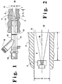
- Figure 1 is a simplified cross-sectional view of one apparatus which may be used to practice this invention.
- FIG. 2 is a simplified view of one embodiment of a fuel injection nozzle which may be used to practice this invention.
- the invention comprises the injection of high velocity fuel and low velocity oxidant fluid in a coaxial relationship into a cavity leading to a furnace zone.
- the fuel and oxidant are injected into the cavity in a staggered arrangement.
- a tangential or angular component is provided to the fluid flow by swirling the oxygen and/or angling the fuel flow.
- the tangential or angular component reduces the length of the flame resulting from the high velocity fuel injection.
- the tangential or angular component may be controlled, for example, by changing swirl vanes or nozzles, thus enabling one to control the flame length.
- refractory wall 2 borders furnace zone 10 where there is contained a furnace atmosphere comprising furnace gases such as, for example, carbon dioxide, water vapor, nitrogen, and/or oxygen.
- furnace atmosphere is generally at an elevated temperature typically exceeding 1000°F and may be as high as 3000°F or more.
- the furnace atmosphere may also contain particulate matter, such as glass batch materials or ash from coal combustion, and/or condensible vapors such as sodium species or acid vapors.
- substantially cylindrical cavity 4 which communicates with furnace zone 10 at opening 11 which has a diameter D.
- opening 11 will have a diameter D less than 3 inches and preferably within the range of from 0.5 to 2.5 inches.
- the very small diameter combined with the cylindrical shape of the cavity and with the defined recess, serves to maintain furnace gases from passing from the furnace zone into the cavity and also reduces the heat passed from the furnace zone into the cavity.
- Burner 12 is positioned for injecting fuel and oxidant into cavity 4.
- Burner 12 comprises central conduit 13 and annular conduit or injector 14 which runs coaxially with central conduit 13.
- Nozzle 3 is positioned on the end of conduit 13 within cavity 4 so as to inject a fuel stream or jet from nozzle 3 in a direction toward opening 11 and then into furnace zone 10.
- the tip of nozzle 3 is recessed from opening 11 by a distance L such that L/D is at least 1.0 but not more than 4.0.
- L/D is within the range of from 1.5 to 3.0.
- the recess of nozzle 3 is sufficient to protect nozzle 3 from damage due to the conditions within furnace zone 10 while not being so great as to cause combustion stream 1 to expand into the walls of cavity 4 prior to entering into furnace zone 10. The most suitable recess will depend upon the furnace temperature; the higher is the furnace temperature the greater would be the recess.
- the fuel is injected out nozzle 3 at a high velocity within the range of from 100 to 700 feet per second, preferably within the range of from 150 to 700 feet per second.
- the fuel may be any fluid which contains combustibles which may combust in the combustion Zone. Among such fuels one can name natural gas, coke oven gas, propane, hydrogen, atomized oil and methane.
- the fuel is provided to burner 12 from fuel source 15 from which it is passed through burner 12 into cavity 4.
- Oxidant fluid is injected into cavity 4 in an annular stream coaxially with the fuel stream from annular injector 14.
- the oxidant fluid is oxygen-enriched air having an oxygen concentration of at least 30 percent, preferably at least 90 percent, or technically pure oxygen having an oxygen concentration of at least 99.5 percent.
- the annular injector injects the oxidant fluid into the cavity 4 preferably at a point further recessed from opening 11 than is the tip of nozzle 3.
- the oxidant fluid is provided to burner 12 from oxidant source 16 from which it is passed through burner 12 into cavity 4.
- the annular or coaxial oxidant fluid stream is injected into cavity 4 at a low velocity not more than 100 feet per second and generally within the range of from 5 to 100, preferably 10 to 50, feet per second.
- the oxidant fluid may be injected into cavity 4 so as to have a swirling motion as it is passed through cavity 4.
- a plurality of vanes 17 positioned proximate the injection end of coaxial injector conduit 14.
- the vanes 17 are angled so as to impart a swirling motion to the oxidant fluid as it flows through cavity 4.
- the swirling motion reduces the axial momentum of the combusting fuel and oxygen stream 1 by directing oxygen radially and also expanding the stream diameter after it leaves cavity 4 thus serving to reduce the length of the resulting flame.
- the degree of swirling may be controlled by adjusting the angle of the vanes.
- furnace gases from the furnace zone are kept from flowing into the cavity by the small diameter of the cavity opening coupled with the widening flame stream passing through the cylindrical cavity.
- the flame is stabilized by the attachment of the flame to the nozzle.
- the stable attachment of the flame to the nozzle is achieved by the oxygen-enriched nature of the oxidant fluid and by the selection of the velocities of the fuel and oxidant fluid within the defined ranges. In this way the requisite flame stability is attained without drawing hot and possibly corrosive furnace gases into the cavity.
- an additional annular oxidant stream may be provided into the cavity without a swirling motion coaxially with the fuel stream and positioned between the fuel stream and the swirling oxidant stream so as to have an outer swirling oxidant stream and an axial co-flowing non-swirling oxidant stream around a central fuel stream.
- the fuel may be injected into cavity 4 through nozzle 3 in a plurality of fuel streams angled from the centerline of cavity 4, generally at an angle within the range of from 1 to 10 degrees.
- Such an arrangement is illustrated in stylized terms in Figure 2.
- the numerals in Figure 2 correspond to those of Figure 1 for the common elements.
- Figure 2 there is shown a plurality of fuel streams injected into cavity 4 each at an angle of 7.5 degrees from the centerline 18 of cavity 4.
- the angular injection of the fuel imparts an angular component to the combusting fuel and oxygen stream, thus serving to reduce the length of the resulting flame.
- the fuel may have a velocity within the range of from 50 to 700 feet per second and the oxidant has a velocity lower than that of the fuel and not more than 100 feet per second.
- Central fuel conduit 13 is metallic and is preferably made of copper to enable heat to be readily conducted away from nozzle 3.
- Nozzle 3 is made of a high temperature alloy such as stainless steel.
- Annular coaxial conduit 14 is preferably made of stainless steel.
- the fuel is injected into cavity 4 through central conduit 13 and nozzle 3 as one or more high velocity streams.
- Oxidant fluid is injected into cavity 4 through annular coaxial conduit 14 as a low velocity annular coaxial stream.
- the oxidant and fuel combust within cavity 4. Because of the low velocity of the oxidant relative to the fuel, the resulting flame is attached to the nozzle and the combustion is stable.
- the stable fuel-oxidant flame 1 attached to fuel nozzle 3 expands slowly and extends out of cavity 4 through opening 11 into furnace zone 10 wherein combustion continues providing heat into the furnace zone and generating furnace gases.
- attachment to the nozzle it is meant that the flame is adjacent the nozzle and is not moved away from the nozzle as in conventional high velocity practice.
- the attachment of the flame to the fuel nozzle enhances the stability of the flame.
- the attachment is brought about by the low velocity annular coaxial oxidant fluid despite the high velocity of the fuel.
- the resulting stable flame and the steady expansion of the combusting stream 1 within cavity 4 serve to substantially maintain furnace gases outside cavity 4 and substantially prevent furnace gases from becoming entrained within cavity 4 despite the large recess between opening 11 and nozzle 3.
- the burner system particularly the nozzle, is protected from damage despite high combustion zone temperatures and the presence of corrosive or condensible species within the furnace gases.
- furnace gases are maintained outside the cavity despite the high velocity of the fuel stream.
- the high velocity of the combusting stream causes furnace gases to aspirate into or become entrained within the combusting stream.
- combustion was carried out without either oxygen swirl or angled fuel injection.
- the fuel velocity was 150 feet per second (fps) and the oxygen velocity was 60 fps.
- the temperature on the other side of the furnace zone at the furnace zone wall opposite the cavity opening was about 2820°F.
- the procedure was repeated except that the oxygen was injected into the cavity having a swirling motion imparted by swirl vanes located within the oxygen injection conduit as illustrated in Figure 1.
- the flame length was reduced over that observed without the oxygen swirl as evidenced by the temperature on the other side of the furnace zone which was only about 2730°F.
- Combustion was carried out with the fuel injected into the cavity at a velocity of 700 fps in four streams, each of which diverged from the cavity centerline at an angle of 5 degrees.
- the oxygen velocity was 60 fps.
- the temperature on the other side of the furnace zone was only about 2790°F despite the very high fuel injection velocity.
- the procedure was repeated except that the oxygen was injected into the cavity having a swirling motion imparted by swirl vanes located within the oxygen injection conduit as illustrated in Figure 1.
- the temperature on the other side of the furnace zone was about 2775°F.
- Combustion was carried out with the fuel injected into the cavity at a velocity of 360 fps in four streams each of which diverged from the cavity centerline at an angle of 5 degrees.
- the oxygen velocity was 60 fps.
- the temperature on the other side of the furnace was about 2785°F: The procedure was repeated except that the oxygen was injected into the cavity having a swirling motion imparted by swirl vanes located within the oxygen injector conduit as illustrated in Figure 1.
- the temperature on the other side of the furnace was 2730°F.
Applications Claiming Priority (2)
| Application Number | Priority Date | Filing Date | Title |
|---|---|---|---|
| US79588 | 1993-06-22 | ||
| US08/079,588 US5449286A (en) | 1993-06-22 | 1993-06-22 | Controlled flame fuel jet combustion |
Publications (3)
| Publication Number | Publication Date |
|---|---|
| EP0631090A2 true EP0631090A2 (de) | 1994-12-28 |
| EP0631090A3 EP0631090A3 (de) | 1995-05-24 |
| EP0631090B1 EP0631090B1 (de) | 1998-03-04 |
Family
ID=22151489
Family Applications (1)
| Application Number | Title | Priority Date | Filing Date |
|---|---|---|---|
| EP94109581A Expired - Lifetime EP0631090B1 (de) | 1993-06-22 | 1994-06-21 | Brennstoffstrahlverbrennung mit kontrollierter Flamme |
Country Status (8)
| Country | Link |
|---|---|
| US (1) | US5449286A (de) |
| EP (1) | EP0631090B1 (de) |
| KR (1) | KR100219745B1 (de) |
| BR (1) | BR9402487A (de) |
| CA (1) | CA2126474C (de) |
| DE (1) | DE69408737T2 (de) |
| ES (1) | ES2114090T3 (de) |
| MX (1) | MX9404702A (de) |
Cited By (2)
| Publication number | Priority date | Publication date | Assignee | Title |
|---|---|---|---|---|
| EP0633228A2 (de) * | 1993-07-06 | 1995-01-11 | Corning Incorporated | Oxy/Fuel Speisekanal für Glasherstellung, Verfahren und Oxy/Fuel Brenner |
| EP0801035A1 (de) * | 1996-04-12 | 1997-10-15 | Praxair Technology, Inc. | Verfahren und Vorrichtung zum Schmelzen von Glas mit verringerter Emission sowie Korrosion des feuerfesten Materials unter Verwendung von Sauerstoffbrennern |
Families Citing this family (54)
| Publication number | Priority date | Publication date | Assignee | Title |
|---|---|---|---|---|
| FR2725017B1 (fr) * | 1994-09-22 | 1996-12-13 | Air Liquide | Ouvreau pour oxybruleur, ensemble d'oxybruleur comportant un tel ouvreau et procede de mise en oeuvre d'un tel ensemble |
| US6481998B2 (en) * | 1995-06-07 | 2002-11-19 | Ge Energy And Environmental Research Corporation | High velocity reburn fuel injector |
| US5839890A (en) * | 1996-09-19 | 1998-11-24 | Praxair Technology, Inc. | Condensation free nozzle |
| EP0911583B1 (de) * | 1997-10-27 | 2003-03-12 | ALSTOM (Switzerland) Ltd | Verfahren zum Betrieb eines Vormischbrenners |
| US6123542A (en) | 1998-11-03 | 2000-09-26 | American Air Liquide | Self-cooled oxygen-fuel burner for use in high-temperature and high-particulate furnaces |
| FR2786555B1 (fr) | 1998-11-30 | 2001-01-19 | Air Liquide | Systeme de combustion a combustible liquide |
| US6126438A (en) * | 1999-06-23 | 2000-10-03 | American Air Liquide | Preheated fuel and oxidant combustion burner |
| US7168269B2 (en) * | 1999-08-16 | 2007-01-30 | The Boc Group, Inc. | Gas injection for glass melting furnace to reduce refractory degradation |
| PL344624A1 (en) | 1999-12-16 | 2001-06-18 | Bloom Eng Co Inc | Burner being feed with an air-fuel mixture |
| US20040091828A1 (en) * | 2000-12-15 | 2004-05-13 | Finke Harry P. | Air and fuel staged burner |
| US6551098B2 (en) | 2001-02-22 | 2003-04-22 | Rheem Manufacturing Company | Variable firing rate fuel burner |
| US6659762B2 (en) | 2001-09-17 | 2003-12-09 | L'air Liquide - Societe Anonyme A' Directoire Et Conseil De Surveillance Pour L'etude Et L'exploitation Des Procedes Georges Claude | Oxygen-fuel burner with adjustable flame characteristics |
| DE102004003343A1 (de) * | 2004-01-22 | 2005-08-11 | Linde Ag | Flexibler Parallelstrombrenner mit Drallkammer |
| US7628606B1 (en) * | 2008-05-19 | 2009-12-08 | Browning James A | Method and apparatus for combusting fuel employing vortex stabilization |
| US8752389B2 (en) * | 2008-11-05 | 2014-06-17 | General Electric Company | Fuel nozzle assembly for use with a gas turbine engine and method of assembling same |
| US8505304B2 (en) * | 2008-12-01 | 2013-08-13 | General Electric Company | Fuel nozzle detachable burner tube with baffle plate assembly |
| US8707740B2 (en) | 2011-10-07 | 2014-04-29 | Johns Manville | Submerged combustion glass manufacturing systems and methods |
| US9096452B2 (en) | 2010-06-17 | 2015-08-04 | Johns Manville | Methods and systems for destabilizing foam in equipment downstream of a submerged combustion melter |
| US8650914B2 (en) | 2010-09-23 | 2014-02-18 | Johns Manville | Methods and apparatus for recycling glass products using submerged combustion |
| US9032760B2 (en) | 2012-07-03 | 2015-05-19 | Johns Manville | Process of using a submerged combustion melter to produce hollow glass fiber or solid glass fiber having entrained bubbles, and burners and systems to make such fibers |
| US8973405B2 (en) | 2010-06-17 | 2015-03-10 | Johns Manville | Apparatus, systems and methods for reducing foaming downstream of a submerged combustion melter producing molten glass |
| US10322960B2 (en) | 2010-06-17 | 2019-06-18 | Johns Manville | Controlling foam in apparatus downstream of a melter by adjustment of alkali oxide content in the melter |
| US8991215B2 (en) | 2010-06-17 | 2015-03-31 | Johns Manville | Methods and systems for controlling bubble size and bubble decay rate in foamed glass produced by a submerged combustion melter |
| US8973400B2 (en) | 2010-06-17 | 2015-03-10 | Johns Manville | Methods of using a submerged combustion melter to produce glass products |
| US8707739B2 (en) | 2012-06-11 | 2014-04-29 | Johns Manville | Apparatus, systems and methods for conditioning molten glass |
| US8997525B2 (en) | 2010-06-17 | 2015-04-07 | Johns Manville | Systems and methods for making foamed glass using submerged combustion |
| US9021838B2 (en) | 2010-06-17 | 2015-05-05 | Johns Manville | Systems and methods for glass manufacturing |
| US8875544B2 (en) | 2011-10-07 | 2014-11-04 | Johns Manville | Burner apparatus, submerged combustion melters including the burner, and methods of use |
| US8769992B2 (en) | 2010-06-17 | 2014-07-08 | Johns Manville | Panel-cooled submerged combustion melter geometry and methods of making molten glass |
| US9776903B2 (en) | 2010-06-17 | 2017-10-03 | Johns Manville | Apparatus, systems and methods for processing molten glass |
| US9533905B2 (en) | 2012-10-03 | 2017-01-03 | Johns Manville | Submerged combustion melters having an extended treatment zone and methods of producing molten glass |
| EP2903941A4 (de) | 2012-10-03 | 2016-06-08 | Johns Manville | Verfahren und systeme zur destabilisierung von schaumstoffen in einer einem unterwasserverbrennungsschmelzofen nachgeschalteten vorrichtung |
| US9227865B2 (en) | 2012-11-29 | 2016-01-05 | Johns Manville | Methods and systems for making well-fined glass using submerged combustion |
| US11142476B2 (en) | 2013-05-22 | 2021-10-12 | Johns Manville | Burner for submerged combustion melting |
| US10131563B2 (en) | 2013-05-22 | 2018-11-20 | Johns Manville | Submerged combustion burners |
| WO2014189501A1 (en) | 2013-05-22 | 2014-11-27 | Johns Manville | Submerged combustion burners, melters, and methods of use |
| WO2014189506A1 (en) | 2013-05-22 | 2014-11-27 | Johns Manville | Submerged combustion burners and melters, and methods of use |
| US9777922B2 (en) | 2013-05-22 | 2017-10-03 | Johns Mansville | Submerged combustion burners and melters, and methods of use |
| PL3003997T3 (pl) | 2013-05-30 | 2021-11-02 | Johns Manville | Palniki do spalania pod powierzchnią cieczy ze środkami usprawniającymi mieszanie przeznaczone do pieców do topienia szkła oraz zastosowanie |
| SI3003996T1 (sl) | 2013-05-30 | 2020-11-30 | Johns Manville | Sistemi potopnega zgorevanja za taljenje stekla in postopki uporabe |
| US10107494B2 (en) * | 2014-04-22 | 2018-10-23 | Universal City Studios Llc | System and method for generating flame effect |
| US9751792B2 (en) | 2015-08-12 | 2017-09-05 | Johns Manville | Post-manufacturing processes for submerged combustion burner |
| US10041666B2 (en) | 2015-08-27 | 2018-08-07 | Johns Manville | Burner panels including dry-tip burners, submerged combustion melters, and methods |
| US10670261B2 (en) | 2015-08-27 | 2020-06-02 | Johns Manville | Burner panels, submerged combustion melters, and methods |
| US9815726B2 (en) | 2015-09-03 | 2017-11-14 | Johns Manville | Apparatus, systems, and methods for pre-heating feedstock to a melter using melter exhaust |
| US9982884B2 (en) | 2015-09-15 | 2018-05-29 | Johns Manville | Methods of melting feedstock using a submerged combustion melter |
| US10837705B2 (en) | 2015-09-16 | 2020-11-17 | Johns Manville | Change-out system for submerged combustion melting burner |
| US10081563B2 (en) | 2015-09-23 | 2018-09-25 | Johns Manville | Systems and methods for mechanically binding loose scrap |
| US10144666B2 (en) | 2015-10-20 | 2018-12-04 | Johns Manville | Processing organics and inorganics in a submerged combustion melter |
| US10246362B2 (en) | 2016-06-22 | 2019-04-02 | Johns Manville | Effective discharge of exhaust from submerged combustion melters and methods |
| US10301208B2 (en) | 2016-08-25 | 2019-05-28 | Johns Manville | Continuous flow submerged combustion melter cooling wall panels, submerged combustion melters, and methods of using same |
| US10337732B2 (en) | 2016-08-25 | 2019-07-02 | Johns Manville | Consumable tip burners, submerged combustion melters including same, and methods |
| US10196294B2 (en) | 2016-09-07 | 2019-02-05 | Johns Manville | Submerged combustion melters, wall structures or panels of same, and methods of using same |
| US10233105B2 (en) | 2016-10-14 | 2019-03-19 | Johns Manville | Submerged combustion melters and methods of feeding particulate material into such melters |
Citations (7)
| Publication number | Priority date | Publication date | Assignee | Title |
|---|---|---|---|---|
| US3836315A (en) * | 1971-10-14 | 1974-09-17 | Pyronics Inc | Burner apparatus for flame propagation control |
| FR2586789A1 (fr) * | 1985-09-05 | 1987-03-06 | Inst Metall Teplo | Procede de combustion d'un combustible gazeux et bruleur pour sa mise en oeuvre |
| EP0340423A2 (de) * | 1988-05-05 | 1989-11-08 | Praxair Technology, Inc. | Brennstoffstrahlbrenner und Verbrennungsverfahren |
| US4986748A (en) * | 1989-12-15 | 1991-01-22 | Corning Incorporated | Wide range oxy-fuel burner and furnace operation |
| US5100313A (en) * | 1991-02-05 | 1992-03-31 | Union Carbide Industrial Gases Technology Corporation | Coherent jet combustion |
| EP0529667A2 (de) * | 1991-08-29 | 1993-03-03 | Praxair Technology, Inc. | Verfahren für Hochgeschwindigkeits-Gaseinspritzung |
| US5267850A (en) * | 1992-06-04 | 1993-12-07 | Praxair Technology, Inc. | Fuel jet burner |
Family Cites Families (17)
| Publication number | Priority date | Publication date | Assignee | Title |
|---|---|---|---|---|
| DE568163C (de) * | 1933-01-16 | Alfred Lanser | In einem Luftzufuehrungsrohr axial eingebauter Druckzerstaeuber fuer fluessige Brennstoffe | |
| US2138998A (en) * | 1936-06-24 | 1938-12-06 | John P Brosius | Burner unit |
| DE1592462C3 (de) * | 1966-08-16 | 1979-07-12 | Montecatini Edison S.P.A., Mailand (Italien) | Vorrichtung zur Verbrennung von Titantetrachlorid |
| US3481680A (en) * | 1967-11-20 | 1969-12-02 | Midland Ross Corp | Direct fired burner |
| US3658289A (en) * | 1969-12-22 | 1972-04-25 | Cities Service Co | Control of fluid dynamics in spiraling gas streams |
| US3905751A (en) * | 1974-03-21 | 1975-09-16 | Midland Ross Corp | Gas burner |
| SU777355A1 (ru) * | 1977-09-30 | 1980-11-07 | Ордена Ленина,Ордена Трудового Красного Знамени Московский Станкостроительный Завод Им.Серго Орджоникидзе | Радиационна горелка |
| US4303386A (en) * | 1979-05-18 | 1981-12-01 | Coen Company, Inc. | Parallel flow burner |
| US4515553A (en) * | 1980-04-10 | 1985-05-07 | Kobe Steel, Ltd. | Combustion method for reducing the emission of nitrogen oxides |
| JPS6026927B2 (ja) * | 1980-05-09 | 1985-06-26 | 日産自動車株式会社 | 噴霧式燃焼装置 |
| SU989245A1 (ru) * | 1981-02-13 | 1983-01-15 | Всесоюзный Научно-Исследовательский Институт Использования Газа В Народном Хозяйстве И Подземного Хранения Нефти,Нефтепродуктов И Сжиженных Газов | Газомазутна горелка |
| CN1007920B (zh) * | 1985-07-15 | 1990-05-09 | 美国氧化公司 | 烃类流体燃料燃烧、控制方法及装置 |
| US4690635A (en) * | 1986-07-21 | 1987-09-01 | Maxon Corporation | High temperature burner assembly |
| IT1235361B (it) * | 1988-04-05 | 1992-06-30 | Termo Tecnica Ceramica Spa | Ugello di tipo misto aria e gas per bruciatori a gas, in particolare bruciatori aventi potenza termica piccola per forni di cottura |
| FR2656676B1 (fr) * | 1989-12-28 | 1994-07-01 | Inst Francais Du Petrole | Bruleur industriel a combustible liquide a faible emission d'oxyde d'azote, ledit bruleur generant plusieurs flammes elementaires et son utilisation. |
| US5199866A (en) * | 1992-03-30 | 1993-04-06 | Air Products And Chemicals, Inc. | Adjustable momentum self-cooled oxy/fuel burner for heating in high temperature environments |
| US5256058A (en) * | 1992-03-30 | 1993-10-26 | Combustion Tec, Inc. | Method and apparatus for oxy-fuel heating with lowered NOx in high temperature corrosive environments |
-
1993
- 1993-06-22 US US08/079,588 patent/US5449286A/en not_active Expired - Lifetime
-
1994
- 1994-06-21 DE DE69408737T patent/DE69408737T2/de not_active Expired - Fee Related
- 1994-06-21 BR BR9402487A patent/BR9402487A/pt not_active IP Right Cessation
- 1994-06-21 ES ES94109581T patent/ES2114090T3/es not_active Expired - Lifetime
- 1994-06-21 EP EP94109581A patent/EP0631090B1/de not_active Expired - Lifetime
- 1994-06-21 KR KR1019940013998A patent/KR100219745B1/ko not_active IP Right Cessation
- 1994-06-21 MX MX9404702A patent/MX9404702A/es not_active Application Discontinuation
- 1994-06-22 CA CA002126474A patent/CA2126474C/en not_active Expired - Fee Related
Patent Citations (7)
| Publication number | Priority date | Publication date | Assignee | Title |
|---|---|---|---|---|
| US3836315A (en) * | 1971-10-14 | 1974-09-17 | Pyronics Inc | Burner apparatus for flame propagation control |
| FR2586789A1 (fr) * | 1985-09-05 | 1987-03-06 | Inst Metall Teplo | Procede de combustion d'un combustible gazeux et bruleur pour sa mise en oeuvre |
| EP0340423A2 (de) * | 1988-05-05 | 1989-11-08 | Praxair Technology, Inc. | Brennstoffstrahlbrenner und Verbrennungsverfahren |
| US4986748A (en) * | 1989-12-15 | 1991-01-22 | Corning Incorporated | Wide range oxy-fuel burner and furnace operation |
| US5100313A (en) * | 1991-02-05 | 1992-03-31 | Union Carbide Industrial Gases Technology Corporation | Coherent jet combustion |
| EP0529667A2 (de) * | 1991-08-29 | 1993-03-03 | Praxair Technology, Inc. | Verfahren für Hochgeschwindigkeits-Gaseinspritzung |
| US5267850A (en) * | 1992-06-04 | 1993-12-07 | Praxair Technology, Inc. | Fuel jet burner |
Cited By (4)
| Publication number | Priority date | Publication date | Assignee | Title |
|---|---|---|---|---|
| EP0633228A2 (de) * | 1993-07-06 | 1995-01-11 | Corning Incorporated | Oxy/Fuel Speisekanal für Glasherstellung, Verfahren und Oxy/Fuel Brenner |
| EP0633228A3 (de) * | 1993-07-06 | 1995-10-18 | Corning Inc | Oxy/Fuel Speisekanal für Glasherstellung, Verfahren und Oxy/Fuel Brenner. |
| US5560758A (en) * | 1993-07-06 | 1996-10-01 | Corning Incorporated | Method for making glass articles |
| EP0801035A1 (de) * | 1996-04-12 | 1997-10-15 | Praxair Technology, Inc. | Verfahren und Vorrichtung zum Schmelzen von Glas mit verringerter Emission sowie Korrosion des feuerfesten Materials unter Verwendung von Sauerstoffbrennern |
Also Published As
| Publication number | Publication date |
|---|---|
| DE69408737D1 (de) | 1998-04-09 |
| CA2126474C (en) | 1997-06-10 |
| US5449286A (en) | 1995-09-12 |
| MX9404702A (es) | 1995-01-31 |
| EP0631090A3 (de) | 1995-05-24 |
| ES2114090T3 (es) | 1998-05-16 |
| KR100219745B1 (ko) | 1999-09-01 |
| KR950001176A (ko) | 1995-01-03 |
| DE69408737T2 (de) | 1998-09-10 |
| EP0631090B1 (de) | 1998-03-04 |
| BR9402487A (pt) | 1995-01-24 |
| CA2126474A1 (en) | 1994-12-23 |
Similar Documents
| Publication | Publication Date | Title |
|---|---|---|
| US5449286A (en) | Controlled flame fuel jet combustion | |
| US5267850A (en) | Fuel jet burner | |
| CA2076909C (en) | Method and apparatus for high velocity gas injection | |
| EP0571984B1 (de) | Lanze in Verbundbauweise | |
| JP2588355B2 (ja) | オキシ・燃料燃焼装置 | |
| US5346390A (en) | Method and apparatus for oxy-fuel heating with lowered NOx in high temperature corrosive environments | |
| CA2303650C (en) | Multiple coherent jet lance | |
| US5931654A (en) | Recessed furnace lance purge gas system | |
| US5580237A (en) | Oxidant lancing nozzle | |
| EP0498378A2 (de) | Verbrennung mit kohärentem Strahl | |
| KR100937947B1 (ko) | 금속, 금속 용탕, 및/또는 슬래그의 건식 야금처리 방법및 주입장치 | |
| US4775314A (en) | Coal gasification burner | |
| US20090311638A1 (en) | Burner and Method for Alternately Implementing Oxycombustion and Air Combustion | |
| EP2232137B1 (de) | Verfahren zur durchführung einer sauerstoffverbrennung | |
| CA2433206A1 (en) | Extensionless coherent jet system with aligned flame envelope ports | |
| EP1441176A1 (de) | Kohärentes Strahlsystem mit nach aussen gerichteten Flammenmantelöffnungen | |
| US6481998B2 (en) | High velocity reburn fuel injector | |
| BR112019021862B1 (pt) | Método e queimador para aquecer um forno para o processamento de metal | |
| US20200386403A1 (en) | Fluid injection element for a furnace or a burner of a furnace and method for operating a furnace | |
| JPS61166906A (ja) | 高炉への燃料吹込み方法 | |
| SK68093A3 (sk) | Spôsob vyvíjania plameňa z kyslíka a paliva s nízkym obsahom NOx a zariadenie na vykonávanie spôsobu | |
| JPH0734108A (ja) | 高炉操業方法 |
Legal Events
| Date | Code | Title | Description |
|---|---|---|---|
| PUAI | Public reference made under article 153(3) epc to a published international application that has entered the european phase |
Free format text: ORIGINAL CODE: 0009012 |
|
| AK | Designated contracting states |
Kind code of ref document: A2 Designated state(s): BE DE ES FR IT NL PT |
|
| PUAL | Search report despatched |
Free format text: ORIGINAL CODE: 0009013 |
|
| AK | Designated contracting states |
Kind code of ref document: A3 Designated state(s): BE DE ES FR IT NL PT |
|
| 17P | Request for examination filed |
Effective date: 19950719 |
|
| 17Q | First examination report despatched |
Effective date: 19961210 |
|
| GRAG | Despatch of communication of intention to grant |
Free format text: ORIGINAL CODE: EPIDOS AGRA |
|
| GRAG | Despatch of communication of intention to grant |
Free format text: ORIGINAL CODE: EPIDOS AGRA |
|
| GRAH | Despatch of communication of intention to grant a patent |
Free format text: ORIGINAL CODE: EPIDOS IGRA |
|
| GRAH | Despatch of communication of intention to grant a patent |
Free format text: ORIGINAL CODE: EPIDOS IGRA |
|
| GRAA | (expected) grant |
Free format text: ORIGINAL CODE: 0009210 |
|
| ITF | It: translation for a ep patent filed |
Owner name: BARZANO' E ZANARDO ROMA S.P.A. |
|
| AK | Designated contracting states |
Kind code of ref document: B1 Designated state(s): BE DE ES FR IT NL PT |
|
| PG25 | Lapsed in a contracting state [announced via postgrant information from national office to epo] |
Ref country code: NL Free format text: LAPSE BECAUSE OF FAILURE TO SUBMIT A TRANSLATION OF THE DESCRIPTION OR TO PAY THE FEE WITHIN THE PRESCRIBED TIME-LIMIT Effective date: 19980304 Ref country code: BE Free format text: LAPSE BECAUSE OF FAILURE TO SUBMIT A TRANSLATION OF THE DESCRIPTION OR TO PAY THE FEE WITHIN THE PRESCRIBED TIME-LIMIT Effective date: 19980304 |
|
| REF | Corresponds to: |
Ref document number: 69408737 Country of ref document: DE Date of ref document: 19980409 |
|
| ET | Fr: translation filed | ||
| REG | Reference to a national code |
Ref country code: ES Ref legal event code: FG2A Ref document number: 2114090 Country of ref document: ES Kind code of ref document: T3 |
|
| PG25 | Lapsed in a contracting state [announced via postgrant information from national office to epo] |
Ref country code: PT Free format text: LAPSE BECAUSE OF FAILURE TO SUBMIT A TRANSLATION OF THE DESCRIPTION OR TO PAY THE FEE WITHIN THE PRESCRIBED TIME-LIMIT Effective date: 19980604 |
|
| NLV1 | Nl: lapsed or annulled due to failure to fulfill the requirements of art. 29p and 29m of the patents act | ||
| PLBE | No opposition filed within time limit |
Free format text: ORIGINAL CODE: 0009261 |
|
| STAA | Information on the status of an ep patent application or granted ep patent |
Free format text: STATUS: NO OPPOSITION FILED WITHIN TIME LIMIT |
|
| 26N | No opposition filed | ||
| PGFP | Annual fee paid to national office [announced via postgrant information from national office to epo] |
Ref country code: FR Payment date: 20040618 Year of fee payment: 11 |
|
| PGFP | Annual fee paid to national office [announced via postgrant information from national office to epo] |
Ref country code: ES Payment date: 20040708 Year of fee payment: 11 |
|
| PGFP | Annual fee paid to national office [announced via postgrant information from national office to epo] |
Ref country code: DE Payment date: 20040802 Year of fee payment: 11 |
|
| PG25 | Lapsed in a contracting state [announced via postgrant information from national office to epo] |
Ref country code: IT Free format text: LAPSE BECAUSE OF NON-PAYMENT OF DUE FEES Effective date: 20050621 |
|
| PG25 | Lapsed in a contracting state [announced via postgrant information from national office to epo] |
Ref country code: ES Free format text: LAPSE BECAUSE OF NON-PAYMENT OF DUE FEES Effective date: 20050622 |
|
| PG25 | Lapsed in a contracting state [announced via postgrant information from national office to epo] |
Ref country code: DE Free format text: LAPSE BECAUSE OF NON-PAYMENT OF DUE FEES Effective date: 20060103 |
|
| PG25 | Lapsed in a contracting state [announced via postgrant information from national office to epo] |
Ref country code: FR Free format text: LAPSE BECAUSE OF NON-PAYMENT OF DUE FEES Effective date: 20060228 |
|
| REG | Reference to a national code |
Ref country code: FR Ref legal event code: ST Effective date: 20060228 |
|
| REG | Reference to a national code |
Ref country code: ES Ref legal event code: FD2A Effective date: 20050622 |