EP0631076B1 - Elektromagnetisches Ventil mit rohrförmigem metallischem Kern - Google Patents
Elektromagnetisches Ventil mit rohrförmigem metallischem Kern Download PDFInfo
- Publication number
- EP0631076B1 EP0631076B1 EP94401329A EP94401329A EP0631076B1 EP 0631076 B1 EP0631076 B1 EP 0631076B1 EP 94401329 A EP94401329 A EP 94401329A EP 94401329 A EP94401329 A EP 94401329A EP 0631076 B1 EP0631076 B1 EP 0631076B1
- Authority
- EP
- European Patent Office
- Prior art keywords
- core
- reel
- hub
- electromagnetic valve
- armature
- Prior art date
- Legal status (The legal status is an assumption and is not a legal conclusion. Google has not performed a legal analysis and makes no representation as to the accuracy of the status listed.)
- Expired - Lifetime
Links
- 239000000463 material Substances 0.000 claims description 5
- 238000004519 manufacturing process Methods 0.000 claims description 2
- 238000000034 method Methods 0.000 claims description 2
- 230000001276 controlling effect Effects 0.000 claims 2
- 230000004907 flux Effects 0.000 claims 1
- 238000000465 moulding Methods 0.000 claims 1
- 230000000149 penetrating effect Effects 0.000 claims 1
- 230000001105 regulatory effect Effects 0.000 claims 1
- 239000002184 metal Substances 0.000 description 5
- 230000000694 effects Effects 0.000 description 3
- 239000000696 magnetic material Substances 0.000 description 3
- 239000006185 dispersion Substances 0.000 description 2
- 238000006073 displacement reaction Methods 0.000 description 2
- 238000003754 machining Methods 0.000 description 2
- 230000002787 reinforcement Effects 0.000 description 2
- 238000010079 rubber tapping Methods 0.000 description 2
- 230000000903 blocking effect Effects 0.000 description 1
- 238000002485 combustion reaction Methods 0.000 description 1
- 125000004122 cyclic group Chemical group 0.000 description 1
- 239000000446 fuel Substances 0.000 description 1
- 239000000203 mixture Substances 0.000 description 1
- 210000000056 organ Anatomy 0.000 description 1
- 230000000284 resting effect Effects 0.000 description 1
- 238000004804 winding Methods 0.000 description 1
Images
Classifications
-
- F—MECHANICAL ENGINEERING; LIGHTING; HEATING; WEAPONS; BLASTING
- F16—ENGINEERING ELEMENTS AND UNITS; GENERAL MEASURES FOR PRODUCING AND MAINTAINING EFFECTIVE FUNCTIONING OF MACHINES OR INSTALLATIONS; THERMAL INSULATION IN GENERAL
- F16K—VALVES; TAPS; COCKS; ACTUATING-FLOATS; DEVICES FOR VENTING OR AERATING
- F16K31/00—Actuating devices; Operating means; Releasing devices
- F16K31/02—Actuating devices; Operating means; Releasing devices electric; magnetic
- F16K31/06—Actuating devices; Operating means; Releasing devices electric; magnetic using a magnet, e.g. diaphragm valves, cutting off by means of a liquid
- F16K31/0644—One-way valve
- F16K31/0655—Lift valves
-
- F—MECHANICAL ENGINEERING; LIGHTING; HEATING; WEAPONS; BLASTING
- F02—COMBUSTION ENGINES; HOT-GAS OR COMBUSTION-PRODUCT ENGINE PLANTS
- F02M—SUPPLYING COMBUSTION ENGINES IN GENERAL WITH COMBUSTIBLE MIXTURES OR CONSTITUENTS THEREOF
- F02M51/00—Fuel-injection apparatus characterised by being operated electrically
- F02M51/06—Injectors peculiar thereto with means directly operating the valve needle
- F02M51/061—Injectors peculiar thereto with means directly operating the valve needle using electromagnetic operating means
- F02M51/0625—Injectors peculiar thereto with means directly operating the valve needle using electromagnetic operating means characterised by arrangement of mobile armatures
- F02M51/0635—Injectors peculiar thereto with means directly operating the valve needle using electromagnetic operating means characterised by arrangement of mobile armatures having a plate-shaped or undulated armature not entering the winding
- F02M51/0639—Injectors peculiar thereto with means directly operating the valve needle using electromagnetic operating means characterised by arrangement of mobile armatures having a plate-shaped or undulated armature not entering the winding the armature acting as a valve
-
- F—MECHANICAL ENGINEERING; LIGHTING; HEATING; WEAPONS; BLASTING
- F16—ENGINEERING ELEMENTS AND UNITS; GENERAL MEASURES FOR PRODUCING AND MAINTAINING EFFECTIVE FUNCTIONING OF MACHINES OR INSTALLATIONS; THERMAL INSULATION IN GENERAL
- F16K—VALVES; TAPS; COCKS; ACTUATING-FLOATS; DEVICES FOR VENTING OR AERATING
- F16K31/00—Actuating devices; Operating means; Releasing devices
- F16K31/02—Actuating devices; Operating means; Releasing devices electric; magnetic
- F16K31/06—Actuating devices; Operating means; Releasing devices electric; magnetic using a magnet, e.g. diaphragm valves, cutting off by means of a liquid
- F16K31/0644—One-way valve
- F16K31/0651—One-way valve the fluid passing through the solenoid coil
-
- H—ELECTRICITY
- H01—ELECTRIC ELEMENTS
- H01F—MAGNETS; INDUCTANCES; TRANSFORMERS; SELECTION OF MATERIALS FOR THEIR MAGNETIC PROPERTIES
- H01F7/00—Magnets
- H01F7/06—Electromagnets; Actuators including electromagnets
- H01F7/08—Electromagnets; Actuators including electromagnets with armatures
- H01F7/16—Rectilinearly-movable armatures
- H01F7/1638—Armatures not entering the winding
-
- Y—GENERAL TAGGING OF NEW TECHNOLOGICAL DEVELOPMENTS; GENERAL TAGGING OF CROSS-SECTIONAL TECHNOLOGIES SPANNING OVER SEVERAL SECTIONS OF THE IPC; TECHNICAL SUBJECTS COVERED BY FORMER USPC CROSS-REFERENCE ART COLLECTIONS [XRACs] AND DIGESTS
- Y10—TECHNICAL SUBJECTS COVERED BY FORMER USPC
- Y10T—TECHNICAL SUBJECTS COVERED BY FORMER US CLASSIFICATION
- Y10T29/00—Metal working
- Y10T29/49—Method of mechanical manufacture
- Y10T29/49002—Electrical device making
- Y10T29/4902—Electromagnet, transformer or inductor
- Y10T29/49073—Electromagnet, transformer or inductor by assembling coil and core
Definitions
- the present invention relates to a metal core solenoid valve tubular and more particularly such a solenoid valve comprising a electromagnetic coil wound on the hub of a material coil plastic, a central metal core placed in the hub of the bobbin, said core forming an axial duct, and an armature capable of being displaced by electromagnetic forces axially towards a end of said axial duct for controlling the gas flow in said conduit, a thread being formed on the surface outer core for position adjustment axial of the core with respect to the reinforcement.
- a solenoid valve is known from document DE-A-1 272 665.
- Such solenoid valves are used in particular in systems supply of fuel mixture to internal combustion engines.
- the coil is supplied with chopped ratio current cyclic can vary from 0 to 100%, so as to vary the distance between the armature, generally supporting a seal, and the end of the central tubular core. This has the effect of determining the flow of the valve for a given value of the differential pressure prevailing on the part and on the other side of the valve.
- the present invention aims to overcome this drawback by providing a solenoid valve of the type mentioned above, not requiring particularly precise machining and whose adjustment is easy and quick to perform.
- the invention firstly relates to a solenoid valve according to claim 1.
- the core is provided with means making it possible to drive it in rotation relative to the bobbin from the outside of the solenoid valve.
- the adjustment of the distance between the reinforcement and the end of the axial duct are made therefore by adjusting the axial position of the core central by simple screwing or unscrewing.
- the core is simply overmolded by plastic of the bobbin, and therefore forms an insert inside the hub of the latter, the first rotation of the core relative to the bobbin has the effect of breaking the bond existing between metal and plastic.
- the thread of the core having the effect of tapping the inner surface of the hub. Due to this tapping, the core remains firmly held inside the bobbin hub, so that when the proper setting is obtained it it is not necessary to fix the core otherwise.
- the solenoid valve according to the invention comprises a magnetic circuit of U-shaped flow return, said armature being arranged to move between the branches of the U.
- the solenoid valve of the invention because that the armature is arranged between the branches of the U, the only tolerances to be met are tolerances radial, much less difficult to respect. Onne otherwise does not encounter dispersion affecting performance because it can be finely tuned the central, functional and motor air gap, between the frame and the core.
- the invention also relates to a method according to claim 4 of manufacture and adjustment of a solenoid valve.
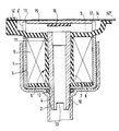
- the organs of this solenoid valve are arranged at the interior of a housing 1 substantially forming a tank cylindrical with an opening at the bottom extended by an exhaust duct 2.
- the top of the tank 1 is closed by a cover (not shown), conveniently mounted, and fitted with a conduit gas inlet.
- a part 3 is placed inside the tank 1.
- This part 3 is formed of a plate of magnetic material curved in the shape of a U whose central part is pierced with a hole 4 and the end of each branch has a 4 'slot.
- a bobbin 5 in plastic material on which a coil is wound 6.
- This bobbin 5 is formed by a hub 7 and two flanges end 8 and 9.
- a core forming a tubular conduit 10 made of magnetic material is arranged coaxially inside the hub 7. It is provided with a thread 11.
- the bobbin 5 is molded onto the conduit 10, so the plastic of this bobbin enters the threads of thread 11.
- the tubular conduit passes through the hole 4 formed in the central part of the frame 3 and penetrates inside of the exhaust duct 2.
- a seal 12 ensures the seal between the outside of the duct 10 and inside the duct 2.
- the end of the conduit 10 engaged in the conduit 2 has slots 13 for pivoting the conduit 10 around its axis using an engaged tool in conduit 2.
- a metal elastic blade 14 is mounted above the assembly which has just been described with one of its ends 14 'fixed relative to this assembly and a 14 '' end capable of sliding parallel to itself to allow the blade 14 to flex.
- This blade 14 carries, on its side facing the end of the conduit 10 which is opposite to that which carries the slots 13, a frame 15 also produced in magnetic material and bearing a seal seal 16 facing the opening of the duct 10.
- the blade 14 In the rest position, the blade 14 is straight and extends substantially perpendicular to the axis of the duct 10 and, in operation, when it is bent towards the core 10, the armature moves between the branches of part 3, perpendicular to these branches, forming two air gaps 17 of very thin.
- the coil 5 is first molded onto the duct tubular 10, then winding 6 is wound on this bobbin.
- the part 3 and the coil thus formed are then introduced into tank 1 with interposition of the seal 12. Finally, the blade 14 carrying the frame 15 and the joint 16 are in place and the valve cover is closed.
- the adjustment is made by inserting a tool inside the duct 2, so as to rotate the conduit 10. This pivoting first of all causes a broken connection between the plastic of the bobbin 5 and the metal of the conduit 10, then a displacement from the latter up towards the frame 15.
- the proper setting which may be determined by any suitable means, the distance between the end opening of the duct and the armature 15 has the desired value and the tool is took of.
Landscapes
- Engineering & Computer Science (AREA)
- General Engineering & Computer Science (AREA)
- Mechanical Engineering (AREA)
- Physics & Mathematics (AREA)
- Electromagnetism (AREA)
- Chemical & Material Sciences (AREA)
- Combustion & Propulsion (AREA)
- Power Engineering (AREA)
- Magnetically Actuated Valves (AREA)
- Valve Device For Special Equipments (AREA)
- Electromagnets (AREA)
Claims (4)
- Elektromagnetisches Ventil, aufweisendeine elektromagnetische Spule (6), die auf die Nabe einer Hülse (5) aus Kunststoff aufgewickelt ist,einen metallischen Zentralkern (10), der in der Nabe (7) der Hülse angeordnet ist, wobei der Zentralkern einen axialen Kanal bildet, und einen Anker (15), der von den elektromagnetischen Kräften axial in Richtung eines Endes des axialen Kanals ausgelenkt werden kann, um die Gasströmung in dem Kanal zu steuern, wobei an der Außenfläche des Zentralkerns ein Gewinde (11) zur Einstellung der Axialposition des Kerns relativ zum Anker ausgebildet ist, dadurch gekennzeichnet,daß das genannte Gewinde mit der Innenfläche der Nabe zusammenwirkt, wobei die Hülse auf den Kern aufgeformt ist.
- Elektromagnetisches Ventil nach Anspruch 1, wobei der Kern mit Mitteln (13) versehen ist, die dessen Drehantrieb relativ zur Hülse von der Ventil-Außenseite aus ermöglichen.
- Elektromagnetisches Ventil nach einem der Ansprüche 1 und 2, wobei ein magnetischer Rückflußkreis (3) in Form eines U vorgesehen ist, wobei der Anker zwischen den Schenkeln des U beweglich angeordnet ist.
- Verfahren zur Herstellung und Steuerung eines elektromagnetischen Ventils, aufweisendeine elektromagnetische Spule (6), die auf die Nabe einer Hülse (5) aus Kunststoff aufgewickelt ist, einen metallischen Zentralkern (10), der in der Nabe (7) der Hülse angeordnet ist, wobei der Zentralkern einen axialen Kanal bildet und an seiner Außenfläche ein Gewinde (11) aufweist, und einen Anker (15), der von den elektrischen Kräften axial in Richtung eines Endes des axialen Kanals ausgelenkt werden kann, um die Gasströmung in dem Kanal zu steuern, gekennzeichnet durch die folgenden Verfahrensschritte:Anformen der Hülse (5) an den Kern (10) derart, daß der Kunststoff der Hülse auf der Außenfläche des Kerns unter Eindringen in dessen Außengewinde haftet;Montieren des elektromagnetischen Ventils;Unterbrechen der Verbindung zwischen der Hülse und dem Kern, wobei der Kern relativ zur Hülse um seine Achse gedreht wird;Einstellen der Axialposition des Kerns nach Maßgabe der Drehbewegung.
Applications Claiming Priority (2)
| Application Number | Priority Date | Filing Date | Title |
|---|---|---|---|
| FR9307250 | 1993-06-16 | ||
| FR9307250A FR2706569B1 (fr) | 1993-06-16 | 1993-06-16 | Electrovanne à noyau métallique tubulaire. |
Publications (2)
| Publication Number | Publication Date |
|---|---|
| EP0631076A1 EP0631076A1 (de) | 1994-12-28 |
| EP0631076B1 true EP0631076B1 (de) | 1999-04-07 |
Family
ID=9448190
Family Applications (1)
| Application Number | Title | Priority Date | Filing Date |
|---|---|---|---|
| EP94401329A Expired - Lifetime EP0631076B1 (de) | 1993-06-16 | 1994-06-14 | Elektromagnetisches Ventil mit rohrförmigem metallischem Kern |
Country Status (8)
| Country | Link |
|---|---|
| US (1) | US5424704A (de) |
| EP (1) | EP0631076B1 (de) |
| JP (1) | JP2761355B2 (de) |
| AT (1) | ATE178697T1 (de) |
| DE (1) | DE69417630T2 (de) |
| ES (1) | ES2133506T3 (de) |
| FR (1) | FR2706569B1 (de) |
| UA (1) | UA37192C2 (de) |
Families Citing this family (18)
| Publication number | Priority date | Publication date | Assignee | Title |
|---|---|---|---|---|
| KR0141942B1 (ko) * | 1994-11-03 | 1998-07-15 | 문정환 | 포토 레지스터 공급량 조절장치 |
| DE19500567B4 (de) * | 1995-01-11 | 2006-02-02 | Robert Bosch Gmbh | Magnetventil |
| EP0813011A1 (de) * | 1996-06-15 | 1997-12-17 | Robert Bosch Gmbh | Elektropneumatischer Druckwandler |
| CN1109943C (zh) * | 1996-11-14 | 2003-05-28 | 福克斯保罗埃卡特股份有限公司 | 电流气压变换器 |
| DE19905722A1 (de) * | 1998-02-24 | 1999-08-26 | Hoerbiger Ventilwerke Gmbh | Gasventil |
| DE19846841C2 (de) * | 1998-10-12 | 2002-06-20 | I E M Ind Entwicklung Medizint | Elektromagnetisches Ventil |
| FR2788324A1 (fr) | 1999-01-08 | 2000-07-13 | Sagem | Siege de clapet d'electrovanne |
| US6548837B1 (en) | 1999-06-08 | 2003-04-15 | Johnson Controls Automotive Electronics | Solenoid bleed valve for a device for the disposal of vapours |
| DE19928207A1 (de) * | 1999-06-19 | 2000-12-21 | Bosch Gmbh Robert | Magnetventil |
| US6310533B2 (en) | 1999-07-20 | 2001-10-30 | Cliftronics, Inc. | Water-resistant encapsulation of solenoid |
| US6220569B1 (en) * | 2000-01-07 | 2001-04-24 | Clippard Instrument Laboratory, Inc. | Electrically controlled proportional valve |
| FR2809860B1 (fr) * | 2000-05-31 | 2002-07-19 | Schneider Electric Ind Sa | Electroaimant avec bobine amovible |
| DE10313854A1 (de) * | 2003-03-27 | 2004-12-09 | Robert Bosch Gmbh | Elektropneumatischer Druckwandler mit temperaturkompensiertem Magnetkreis |
| US7748683B1 (en) | 2007-02-23 | 2010-07-06 | Kelly Edmund F | Electrically controlled proportional valve |
| DE102008020042A1 (de) * | 2008-04-21 | 2009-10-22 | Pierburg Gmbh | Elektromagnetventil |
| JP5614585B2 (ja) * | 2010-11-02 | 2014-10-29 | アイシン精機株式会社 | 流体制御弁 |
| DE102011056853A1 (de) * | 2011-12-22 | 2013-06-27 | Eto Magnetic Gmbh | Spulenträger sowie elektromagnetische Stellvorrichtung mit Spulenträger |
| US11754196B2 (en) * | 2018-10-22 | 2023-09-12 | Johnson & Johnson Surgical Vision, Inc. | Electromagnetic actuation of elastomeric valve for fluid flow control |
Family Cites Families (4)
| Publication number | Priority date | Publication date | Assignee | Title |
|---|---|---|---|---|
| DE1272665B (de) * | 1966-11-04 | 1968-07-11 | Teldix Luftfahrt Ausruestung | Elektromagnetisch betaetigbares Ventil mit justierbarem Hub |
| FR1605244A (de) * | 1967-06-30 | 1973-09-14 | ||
| AU8211375A (en) * | 1974-06-29 | 1976-12-16 | Lucas Electrical Co Ltd | Fuel injection nozzle |
| US4515129A (en) * | 1983-06-10 | 1985-05-07 | General Motors Corporation | Edge discharge pulse fuel injector |
-
1993
- 1993-06-16 FR FR9307250A patent/FR2706569B1/fr not_active Expired - Lifetime
-
1994
- 1994-06-14 AT AT94401329T patent/ATE178697T1/de active
- 1994-06-14 EP EP94401329A patent/EP0631076B1/de not_active Expired - Lifetime
- 1994-06-14 ES ES94401329T patent/ES2133506T3/es not_active Expired - Lifetime
- 1994-06-14 DE DE69417630T patent/DE69417630T2/de not_active Expired - Lifetime
- 1994-06-15 JP JP6133205A patent/JP2761355B2/ja not_active Expired - Lifetime
- 1994-06-15 US US08/259,861 patent/US5424704A/en not_active Expired - Lifetime
- 1994-06-16 UA UA94005264A patent/UA37192C2/uk unknown
Also Published As
| Publication number | Publication date |
|---|---|
| EP0631076A1 (de) | 1994-12-28 |
| ES2133506T3 (es) | 1999-09-16 |
| US5424704A (en) | 1995-06-13 |
| DE69417630D1 (de) | 1999-05-12 |
| JP2761355B2 (ja) | 1998-06-04 |
| ATE178697T1 (de) | 1999-04-15 |
| FR2706569A1 (fr) | 1994-12-23 |
| FR2706569B1 (fr) | 1995-09-29 |
| UA37192C2 (uk) | 2001-05-15 |
| DE69417630T2 (de) | 1999-11-04 |
| JPH0757932A (ja) | 1995-03-03 |
Similar Documents
| Publication | Publication Date | Title |
|---|---|---|
| EP0631076B1 (de) | Elektromagnetisches Ventil mit rohrförmigem metallischem Kern | |
| EP0713036B1 (de) | Elektromagnetisches Ventil und Brennstoffdampfrückführungskreis einer Brennkraftmaschine | |
| EP1040266A1 (de) | Abgasrückführventil für eine brennkraftmaschine | |
| FR2533291A1 (fr) | Procede et dispositif pour commander au moins une section transversale d'etranglement dans une conduite de commande | |
| WO1998048204A1 (fr) | Vanne papillon pour la regulation du debit d'un fluide | |
| LU85911A1 (fr) | Soupape a fermeture automatique en cas de fuites de gaz | |
| EP1556640A1 (de) | Linearventilstellglied | |
| EP0631075A1 (de) | Elektromagnetisches Doppelsitzventil und Dampfrückführungskreis | |
| FR2509466A1 (fr) | Capteur de deplacement inductif pour organe de reglage fluidique | |
| FR2670243A1 (fr) | Systeme de regulation du debit d'air dans un corps a etranglement d'un dispositif d'alimentation de moteur a combustion interne pour vehicules. | |
| FR2764001A1 (fr) | Carburateur pour un moteur a combustion interne | |
| US20200240333A1 (en) | Throttle device | |
| FR2643318A1 (fr) | Actionneur, notamment pour la commande d'orientation d'un projecteur | |
| FR2695962A1 (fr) | Dispositif de régulation du ralenti d'un moteur thermique pour la commande de la quantité de fluide alimentant le moteur thermique. | |
| FR2640330A1 (fr) | Dispositif de fixation a un element de structure interne d'un vehicule automobile d'une piece d'equipement a positionner relativement a un element de structure externe du vehicule | |
| FR2695166A1 (fr) | Dispositif de coupure de secours pour un moteur à combustion interne à injection à suralimentation. | |
| FR2605155A1 (fr) | Frein electromagnetique, notamment pour moteur-frein | |
| EP0085586B1 (de) | Schlossbedienung mit Druckknopf | |
| FR2692024A1 (fr) | Brûleur à gaz, comportant des moyens d'alignement de l'injecteur et du mélangeur. | |
| EP3683150B1 (de) | Verbindungsvorrichtung, die zwischen mindestens zwei teilen schwenkbar ist, luftfahrzeug, das eine abdeckung umfasst, die mit dieser schwenkbaren verbindungsvorrichtung ausgestattet ist | |
| FR2497553A1 (fr) | Valve papillon d'aspiration avec reglage du debit de fuite | |
| FR2782963A1 (fr) | Dispositif de commande d'une partie mobile d'un projecteur de vehicule automobile | |
| FR2866939A1 (fr) | Soupape | |
| FR2618868A1 (fr) | Dispositif formant detendeur de regulation automatique de pression d'un fluide gazeux | |
| EP0220987A1 (de) | Unterdruckbremskraftverstärker und Verfahren zu seiner Regelung |
Legal Events
| Date | Code | Title | Description |
|---|---|---|---|
| PUAI | Public reference made under article 153(3) epc to a published international application that has entered the european phase |
Free format text: ORIGINAL CODE: 0009012 |
|
| AK | Designated contracting states |
Kind code of ref document: A1 Designated state(s): AT BE CH DE DK ES FR GB GR IE IT LI LU MC NL PT SE |
|
| RAX | Requested extension states of the european patent have changed |
Free format text: SI PAYMENT 940621 |
|
| 17P | Request for examination filed |
Effective date: 19950612 |
|
| 17Q | First examination report despatched |
Effective date: 19960926 |
|
| GRAG | Despatch of communication of intention to grant |
Free format text: ORIGINAL CODE: EPIDOS AGRA |
|
| GRAG | Despatch of communication of intention to grant |
Free format text: ORIGINAL CODE: EPIDOS AGRA |
|
| GRAH | Despatch of communication of intention to grant a patent |
Free format text: ORIGINAL CODE: EPIDOS IGRA |
|
| GRAH | Despatch of communication of intention to grant a patent |
Free format text: ORIGINAL CODE: EPIDOS IGRA |
|
| GRAA | (expected) grant |
Free format text: ORIGINAL CODE: 0009210 |
|
| AK | Designated contracting states |
Kind code of ref document: B1 Designated state(s): AT BE CH DE DK ES FR GB GR IE IT LI LU MC NL PT SE |
|
| AX | Request for extension of the european patent |
Free format text: SI PAYMENT 940621 |
|
| PG25 | Lapsed in a contracting state [announced via postgrant information from national office to epo] |
Ref country code: SE Free format text: THE PATENT HAS BEEN ANNULLED BY A DECISION OF A NATIONAL AUTHORITY Effective date: 19990407 Ref country code: NL Free format text: LAPSE BECAUSE OF FAILURE TO SUBMIT A TRANSLATION OF THE DESCRIPTION OR TO PAY THE FEE WITHIN THE PRESCRIBED TIME-LIMIT Effective date: 19990407 Ref country code: GR Free format text: LAPSE BECAUSE OF NON-PAYMENT OF DUE FEES Effective date: 19990407 Ref country code: AT Free format text: LAPSE BECAUSE OF FAILURE TO SUBMIT A TRANSLATION OF THE DESCRIPTION OR TO PAY THE FEE WITHIN THE PRESCRIBED TIME-LIMIT Effective date: 19990407 |
|
| REF | Corresponds to: |
Ref document number: 178697 Country of ref document: AT Date of ref document: 19990415 Kind code of ref document: T |
|
| REG | Reference to a national code |
Ref country code: CH Ref legal event code: EP |
|
| REG | Reference to a national code |
Ref country code: IE Ref legal event code: FG4D Free format text: FRENCH |
|
| REF | Corresponds to: |
Ref document number: 69417630 Country of ref document: DE Date of ref document: 19990512 |
|
| PG25 | Lapsed in a contracting state [announced via postgrant information from national office to epo] |
Ref country code: LU Free format text: LAPSE BECAUSE OF NON-PAYMENT OF DUE FEES Effective date: 19990614 |
|
| PG25 | Lapsed in a contracting state [announced via postgrant information from national office to epo] |
Ref country code: LI Free format text: LAPSE BECAUSE OF NON-PAYMENT OF DUE FEES Effective date: 19990630 Ref country code: CH Free format text: LAPSE BECAUSE OF NON-PAYMENT OF DUE FEES Effective date: 19990630 Ref country code: BE Free format text: LAPSE BECAUSE OF NON-PAYMENT OF DUE FEES Effective date: 19990630 |
|
| PG25 | Lapsed in a contracting state [announced via postgrant information from national office to epo] |
Ref country code: PT Free format text: LAPSE BECAUSE OF FAILURE TO SUBMIT A TRANSLATION OF THE DESCRIPTION OR TO PAY THE FEE WITHIN THE PRESCRIBED TIME-LIMIT Effective date: 19990707 Ref country code: DK Free format text: LAPSE BECAUSE OF FAILURE TO SUBMIT A TRANSLATION OF THE DESCRIPTION OR TO PAY THE FEE WITHIN THE PRESCRIBED TIME-LIMIT Effective date: 19990707 |
|
| GBT | Gb: translation of ep patent filed (gb section 77(6)(a)/1977) |
Effective date: 19990714 |
|
| NLV1 | Nl: lapsed or annulled due to failure to fulfill the requirements of art. 29p and 29m of the patents act | ||
| REG | Reference to a national code |
Ref country code: ES Ref legal event code: FG2A Ref document number: 2133506 Country of ref document: ES Kind code of ref document: T3 |
|
| PG25 | Lapsed in a contracting state [announced via postgrant information from national office to epo] |
Ref country code: IE Free format text: LAPSE BECAUSE OF NON-PAYMENT OF DUE FEES Effective date: 19991206 |
|
| BERE | Be: lapsed |
Owner name: S.A. SAGEM ALLUMAGE Effective date: 19990630 |
|
| PG25 | Lapsed in a contracting state [announced via postgrant information from national office to epo] |
Ref country code: MC Free format text: LAPSE BECAUSE OF NON-PAYMENT OF DUE FEES Effective date: 19991231 |
|
| REG | Reference to a national code |
Ref country code: IE Ref legal event code: FD4D |
|
| PLBE | No opposition filed within time limit |
Free format text: ORIGINAL CODE: 0009261 |
|
| STAA | Information on the status of an ep patent application or granted ep patent |
Free format text: STATUS: NO OPPOSITION FILED WITHIN TIME LIMIT |
|
| REG | Reference to a national code |
Ref country code: CH Ref legal event code: PL |
|
| GBPC | Gb: european patent ceased through non-payment of renewal fee |
Effective date: 19990707 |
|
| REG | Reference to a national code |
Ref country code: GB Ref legal event code: 728V |
|
| REG | Reference to a national code |
Ref country code: GB Ref legal event code: 728Y |
|
| 26N | No opposition filed | ||
| REG | Reference to a national code |
Ref country code: GB Ref legal event code: IF02 |
|
| PGFP | Annual fee paid to national office [announced via postgrant information from national office to epo] |
Ref country code: ES Payment date: 20120625 Year of fee payment: 19 |
|
| PGFP | Annual fee paid to national office [announced via postgrant information from national office to epo] |
Ref country code: GB Payment date: 20130620 Year of fee payment: 20 Ref country code: DE Payment date: 20130611 Year of fee payment: 20 |
|
| PGFP | Annual fee paid to national office [announced via postgrant information from national office to epo] |
Ref country code: IT Payment date: 20130618 Year of fee payment: 20 |
|
| PGFP | Annual fee paid to national office [announced via postgrant information from national office to epo] |
Ref country code: FR Payment date: 20130726 Year of fee payment: 20 |
|
| REG | Reference to a national code |
Ref country code: DE Ref legal event code: R071 Ref document number: 69417630 Country of ref document: DE |
|
| REG | Reference to a national code |
Ref country code: GB Ref legal event code: PE20 Expiry date: 20140613 |
|
| PG25 | Lapsed in a contracting state [announced via postgrant information from national office to epo] |
Ref country code: GB Free format text: LAPSE BECAUSE OF EXPIRATION OF PROTECTION Effective date: 20140613 |
|
| PG25 | Lapsed in a contracting state [announced via postgrant information from national office to epo] |
Ref country code: DE Free format text: LAPSE BECAUSE OF EXPIRATION OF PROTECTION Effective date: 20140617 |
|
| REG | Reference to a national code |
Ref country code: ES Ref legal event code: FD2A Effective date: 20140926 |
|
| PG25 | Lapsed in a contracting state [announced via postgrant information from national office to epo] |
Ref country code: ES Free format text: LAPSE BECAUSE OF EXPIRATION OF PROTECTION Effective date: 20140615 |