EP0629376B1 - Fahrbares Röntgengerät - Google Patents
Fahrbares Röntgengerät Download PDFInfo
- Publication number
- EP0629376B1 EP0629376B1 EP94107381A EP94107381A EP0629376B1 EP 0629376 B1 EP0629376 B1 EP 0629376B1 EP 94107381 A EP94107381 A EP 94107381A EP 94107381 A EP94107381 A EP 94107381A EP 0629376 B1 EP0629376 B1 EP 0629376B1
- Authority
- EP
- European Patent Office
- Prior art keywords
- stand
- chassis
- ray
- control panel
- mobile
- Prior art date
- Legal status (The legal status is an assumption and is not a legal conclusion. Google has not performed a legal analysis and makes no representation as to the accuracy of the status listed.)
- Expired - Lifetime
Links
- 238000009826 distribution Methods 0.000 claims description 3
- 230000000712 assembly Effects 0.000 description 1
- 238000000429 assembly Methods 0.000 description 1
- 230000005484 gravity Effects 0.000 description 1
Images
Classifications
-
- A—HUMAN NECESSITIES
- A61—MEDICAL OR VETERINARY SCIENCE; HYGIENE
- A61B—DIAGNOSIS; SURGERY; IDENTIFICATION
- A61B6/00—Apparatus or devices for radiation diagnosis; Apparatus or devices for radiation diagnosis combined with radiation therapy equipment
- A61B6/44—Constructional features of apparatus for radiation diagnosis
- A61B6/4405—Constructional features of apparatus for radiation diagnosis the apparatus being movable or portable, e.g. handheld or mounted on a trolley
Definitions
- Mobile x-ray devices which have a control panel, a tripod and an x-ray emitter mounted on the tripod on a chassis.
- the stand with the X-ray emitter can be swiveled about a vertical axis relative to the chassis so that the X-ray device can be positioned and maneuvered easily.
- the stand is pivotally connected to the chassis (DE-OS 2 212 510, US Pat. No. 5,067,145).
- DE-U-85 21 246 describes a similar mobile X-ray device in which an operating console is pivotally connected to the stand.
- the individual components connected to the chassis are individually adjustable so that an optimal weight distribution is not always guaranteed.
- the invention has for its object to design an X-ray device of the type mentioned in such a way that, regardless of the respective pivoting angle of the X-ray emitter, there is always approximately the same weight distribution.
- control panel with the components arranged therein acts permanently as a counterweight to the X-ray emitter. This is not the case with the solution according to US Pat. No. 5,067,145, in which only the x-ray emitter can be pivoted about a vertical axis relative to the chassis.
- the invention makes it possible to set up the chassis parallel to a bed. Driving under the bed, which must be done in the prior art because of the required stability, can be omitted.
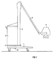
- a chassis 1 which can be moved on the floor of a room and carries a control panel 2 and a tripod 3.
- An x-ray emitter 5 is connected to the stand 3 via a swivel arm 4.
- control panel 2 and the tripod 3 are fastened to a mounting base plate 7 which is connected to the chassis 1 so as to be pivotable about a vertical axis 6.
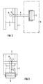
- FIG. 2 shows the X-ray device according to FIG. 1 in the working position.
- the chassis 1 is aligned parallel to a bed 8 and the x-ray emitter 5 is pivoted about the axis 6 by 90 ° with respect to FIG. 1, so that it lies above the patient lying on the bed 8. It is not necessary to drive the bed 8 under the chassis 1, since the control panel 2 represents a counterweight to the X-ray emitter 5.
- FIG 3 shows all the components of the x-ray device in the park position, in which the arm 4 with the x-ray emitter 5 lies parallel to the two arms of the chassis 1 and is moved all the way down.
Landscapes
- Health & Medical Sciences (AREA)
- Life Sciences & Earth Sciences (AREA)
- Medical Informatics (AREA)
- Engineering & Computer Science (AREA)
- Radiology & Medical Imaging (AREA)
- Biomedical Technology (AREA)
- Biophysics (AREA)
- Nuclear Medicine, Radiotherapy & Molecular Imaging (AREA)
- Optics & Photonics (AREA)
- Pathology (AREA)
- Physics & Mathematics (AREA)
- High Energy & Nuclear Physics (AREA)
- Heart & Thoracic Surgery (AREA)
- Molecular Biology (AREA)
- Surgery (AREA)
- Animal Behavior & Ethology (AREA)
- General Health & Medical Sciences (AREA)
- Public Health (AREA)
- Veterinary Medicine (AREA)
- Apparatus For Radiation Diagnosis (AREA)
Description
- Es sind fahrbare Röntgengeräte bekannt, die auf einem Fahrgestell ein Bedienpult, ein Stativ und einen am Stativ gelagerten Röntgenstrahler aufweisen. Das Stativ mit dem Röntgenstrahler ist dabei relativ zum Fahrgestell um eine vertikale Achse schwenkbar, damit das Röntgengerät gut positionierbar und manövrierbar ist. Hierzu ist das Stativ mit dem Fahrgestell schwenkbar verbunden (DE-OS 2 212 510, US-PS 5 067 145). Diese Lösung bringt Probleme hinsichtlich der Kippsicherheit aufgrund der Schwerpunktverlagerung und erfordert zusätzliche Maßnahmen im Bereich der Fußbaugruppen.
- In DE-U-85 21 246 ist ein ähnliches fahrbares Röntgengerät beschrieben, bei dem mit dem Stativ ein Bedienpult schwenkbar verbunden ist. Die einzelnen, mit dem Fahrgestell verbundenen Komponenten sind individuell einstellbar, so daß eine optimale Gewichtsverteilung nicht immer gewährleistet ist.
- Der Erfindung liegt die Aufgabe zugrunde, ein Röntgengerät der eingangs genannten Art so auszubilden, daß unabhängig vom jeweiligen Schwenkwinkel des Röntgenstrahlers immer etwa gleiche Gewichtsverteilungen herrschen.
- Diese Aufgabe ist erfindungsgemäß gelöst durch die Merkmale des Patentanspruches 1. Der Vorteil der erfindungsgemäßen Lösung besteht darin, daß das Bedienpult mit den darin angeordneten Komponenten permanent als Gegengewicht zum Röntgenstrahler wirkt. Dies ist bei der Lösung gemäß der US-PS 5 067 145 nicht der Fall, bei der nur der Röntgenstrahler relativ zum Fahrgestell um eine vertikale Achse verschwenkbar ist. Durch die Erfindung ist es möglich, das Fahrgestell parallel neben einem Bett aufzustellen. Ein Unterfahren des Bettes, das beim Stand der Technik wegen der erforderlichen Standsicherheit erfolgen muß, kann entfallen.
- Die Erfindung ist nachfolgend anhand eines in der Zeichnung in drei verschiedenen Ansichten in den FIG 1 bis 3 dargestellten Ausführungsbeispiels näher erläutert.
- In der Zeichnung ist ein Fahrgestell 1 dargestellt, das auf dem Boden eines Raumes verfahrbar ist und ein Bedienpult 2 sowie ein Stativ 3 trägt. Ein Röntgenstrahler 5 ist mit dem Stativ 3 über einen Schwenkarm 4 verbunden.
- Das Bedienpult 2 und das Stativ 3 sind auf einer Montagegrundplatte 7 befestigt, welche um eine vertikale Achse 6 schwenkbar mit dem Fahrgestell 1 verbunden ist.
- Die FIG 2 zeigt das Röntgengerät gemäß FIG 1 in der Arbeitsstellung. Das Fahrgestell 1 ist parallel zu einem Bett 8 ausgerichtet und der Röntgenstrahler 5 ist um die Achse 6 um 90° gegenüber der FIG 1 geschwenkt, so daß er über dem auf dem Bett 8 liegenden Patienten liegt. Ein Unterfahren des Bettes 8 mit dem Fahrgestell 1 ist nicht erforderlich, da das Bedienpult 2 ein Gegengewicht zum Röntgenstrahler 5 darstellt.
- Die FIG 3 zeigt alle Komponenten des Röntgengerätes in Parkstellung, in der der Arm 4 mit dem Röntgenstrahler 5 parallel zu den beiden Auslegern des Fahrgestells 1 liegt und ganz nach unten gefahren ist.
Claims (1)
- Fahrbares Röntgengerät, bei dem auf einem Fahrgestell (1) angeordnet sind:
Ein Bedienpult (2), ein Stativ (3) und ein am Stativ (3) gelagerter Röntgenstrahler (5), wobei das Stativ (3) mit dem Röntgenstrahler (5) relativ zu dem Fahrgestell um eine vertikale Achse (6) schwenkbar ist, dadurch gekennzeichnet, daß das Bedienpult (2) und das Stativ (3) auf einer Montagegrundplatte (7) befestigt sind, welche mit dem Fahrgestell (1) um eine vertikale Achse drehbar verbunden ist, derart, daß unabhängig vom jeweiligen Schwenkbereich des Röntgenstrahlers (5) immer etwa gleiche Gewichtsverteilungen herrschen.
Applications Claiming Priority (2)
| Application Number | Priority Date | Filing Date | Title |
|---|---|---|---|
| DE4317713A DE4317713C1 (de) | 1993-05-27 | 1993-05-27 | Fahrbares Röntgengerät |
| DE4317713 | 1993-05-27 |
Publications (2)
| Publication Number | Publication Date |
|---|---|
| EP0629376A1 EP0629376A1 (de) | 1994-12-21 |
| EP0629376B1 true EP0629376B1 (de) | 1997-10-15 |
Family
ID=6489091
Family Applications (1)
| Application Number | Title | Priority Date | Filing Date |
|---|---|---|---|
| EP94107381A Expired - Lifetime EP0629376B1 (de) | 1993-05-27 | 1994-05-11 | Fahrbares Röntgengerät |
Country Status (4)
| Country | Link |
|---|---|
| US (1) | US5506883A (de) |
| EP (1) | EP0629376B1 (de) |
| JP (1) | JP3004665U (de) |
| DE (2) | DE4317713C1 (de) |
Families Citing this family (8)
| Publication number | Priority date | Publication date | Assignee | Title |
|---|---|---|---|---|
| DE19631246A1 (de) * | 1996-08-02 | 1998-02-05 | Juergen Ziehm | Fahrbares chirurgisches Röntgendiagnostikgerät |
| DE19641628C2 (de) * | 1996-10-09 | 2003-12-18 | Siemens Ag | Medizinische Untersuchungsanlage |
| US5784435A (en) * | 1997-04-23 | 1998-07-21 | General Electric Company | X-ray tube support column on a mobile x-ray product with improved rotational flexibility |
| WO2004075975A2 (en) * | 2003-02-24 | 2004-09-10 | Pomper Mark E | Mobile radiation treatment vehicle and method |
| US8657354B2 (en) | 2006-05-19 | 2014-02-25 | Breya, Llc. | Mobile radiation therapy |
| US8459714B2 (en) | 2006-05-19 | 2013-06-11 | Breya, Llc. | Mobile radiation therapy |
| JP6066247B1 (ja) * | 2015-11-26 | 2017-01-25 | 富士フイルム株式会社 | 放射線照射装置 |
| JP6859898B2 (ja) * | 2017-08-25 | 2021-04-14 | 株式会社島津製作所 | 移動型放射線撮影装置 |
Family Cites Families (9)
| Publication number | Priority date | Publication date | Assignee | Title |
|---|---|---|---|---|
| US1775853A (en) * | 1928-09-24 | 1930-09-16 | Engeln Electric Company | Radiographic unit |
| DE2212510C3 (de) * | 1972-03-15 | 1975-12-11 | Siemens Ag, 1000 Berlin Und 8000 Muenchen | Fahrbares Röntgenuntersuchungsgerät |
| DE7525125U (de) * | 1975-08-07 | 1977-02-03 | Siemens Ag, 1000 Berlin Und 8000 Muenchen | Vorrichtung zur Halterung eines Ultraschall-Diagnostikgerätes |
| DE8521246U1 (de) * | 1985-07-23 | 1986-02-20 | Picker International GmbH, 8000 München | Fahrbares Röntgendiagnosegerät |
| NL8600227A (nl) * | 1986-01-31 | 1987-08-17 | Philips Nv | Mobiel roentgen bv apparaat. |
| JPS63296743A (ja) * | 1987-05-29 | 1988-12-02 | Mitaka Koki Kk | 医療用光学機器のスタンド装置 |
| DE8709994U1 (de) * | 1987-07-21 | 1987-09-17 | Siemens AG, 1000 Berlin und 8000 München | Röntgenuntersuchungsgerät mit einem C-Bogen |
| US5067145A (en) * | 1990-03-16 | 1991-11-19 | Siczek Bernard W | Mobile X-ray apparatus |
| DE4202922A1 (de) * | 1992-02-01 | 1993-08-05 | Zeiss Carl Fa | Motorisches stativ |
-
1993
- 1993-05-27 DE DE4317713A patent/DE4317713C1/de not_active Expired - Fee Related
-
1994
- 1994-03-23 US US08/216,314 patent/US5506883A/en not_active Expired - Fee Related
- 1994-05-11 DE DE59404307T patent/DE59404307D1/de not_active Expired - Fee Related
- 1994-05-11 EP EP94107381A patent/EP0629376B1/de not_active Expired - Lifetime
- 1994-05-26 JP JP1994005859U patent/JP3004665U/ja not_active Expired - Lifetime
Also Published As
| Publication number | Publication date |
|---|---|
| DE59404307D1 (de) | 1997-11-20 |
| DE4317713C1 (de) | 1994-06-23 |
| EP0629376A1 (de) | 1994-12-21 |
| US5506883A (en) | 1996-04-09 |
| JP3004665U (ja) | 1994-11-22 |
Similar Documents
| Publication | Publication Date | Title |
|---|---|---|
| DE10147602B4 (de) | Unbegrenzt neigbarer Kamerakran | |
| DE4423402C2 (de) | Stützsäule zur Halterung einer Patientenlagerfläche | |
| EP0405234B1 (de) | Mobiles Röntgengerät | |
| EP3346457B1 (de) | Monitorsystem | |
| EP2025532A2 (de) | Präsentationssystem | |
| EP0629376B1 (de) | Fahrbares Röntgengerät | |
| DE68925681T2 (de) | Rahmenkonstruktion für einen Abtaster für die Computertomographie | |
| EP0956551B1 (de) | Bewegungssimulator | |
| DE102011006505A1 (de) | Mobiles C-Bogen-Röntgengerät mit einer Kippschutzeinrichtung | |
| EP0230236A1 (de) | Einrichtung zum Positionieren von Informationsgeräten | |
| EP0332937A1 (de) | Röntgenuntersuchungseinrichtung mit zwei Bildaufnahmeeinheiten | |
| DE3408172C2 (de) | ||
| EP1034741A1 (de) | Bedienplatz eines Röntgenprüfgerätes | |
| DE3425650A1 (de) | Roentgenuntersuchungsgeraet mit einem c- oder u-foermigen traeger fuer den roentgenstrahler und die bildaufnahmevorrichtung | |
| DE3427229C2 (de) | ||
| DE3014489A1 (de) | Montagewagen | |
| DE3933237A1 (de) | Tisch mit tischgestell und tischplatte sowie stelleinrichtung zum veraendern der hoehe und neigung der tischplatte | |
| DE2747583C2 (de) | Röntgenuntersuchungsgerät | |
| DE2037380B2 (de) | Verteilförderanlage mit kippbaren Plattformen | |
| DE19923726C1 (de) | Vergnügungsgerät mit einer Überschlagschaukel | |
| DE3931574A1 (de) | Gestell fuer bildschirmgeraete | |
| EP0419950A1 (de) | Röntgenuntersuchungsgerät | |
| DE19627455C1 (de) | Vorrichtung zum ferngesteuerten Positionieren von Kameras an verschiedene Stellen eines Vorgangsbereiches | |
| DE102019214901A1 (de) | Radiographiesystem mit bodenmontierter Trägereinheit | |
| EP1899206A1 (de) | Fahrzeug mit einer arbeitsbühne |
Legal Events
| Date | Code | Title | Description |
|---|---|---|---|
| PUAI | Public reference made under article 153(3) epc to a published international application that has entered the european phase |
Free format text: ORIGINAL CODE: 0009012 |
|
| AK | Designated contracting states |
Kind code of ref document: A1 Designated state(s): DE FR GB IT |
|
| 17P | Request for examination filed |
Effective date: 19950119 |
|
| 17Q | First examination report despatched |
Effective date: 19960823 |
|
| GRAG | Despatch of communication of intention to grant |
Free format text: ORIGINAL CODE: EPIDOS AGRA |
|
| GRAH | Despatch of communication of intention to grant a patent |
Free format text: ORIGINAL CODE: EPIDOS IGRA |
|
| GRAH | Despatch of communication of intention to grant a patent |
Free format text: ORIGINAL CODE: EPIDOS IGRA |
|
| GRAA | (expected) grant |
Free format text: ORIGINAL CODE: 0009210 |
|
| AK | Designated contracting states |
Kind code of ref document: B1 Designated state(s): DE FR GB IT |
|
| REF | Corresponds to: |
Ref document number: 59404307 Country of ref document: DE Date of ref document: 19971120 |
|
| ET | Fr: translation filed | ||
| GBT | Gb: translation of ep patent filed (gb section 77(6)(a)/1977) |
Effective date: 19971203 |
|
| ITF | It: translation for a ep patent filed | ||
| PGFP | Annual fee paid to national office [announced via postgrant information from national office to epo] |
Ref country code: GB Payment date: 19980414 Year of fee payment: 5 |
|
| PLBE | No opposition filed within time limit |
Free format text: ORIGINAL CODE: 0009261 |
|
| STAA | Information on the status of an ep patent application or granted ep patent |
Free format text: STATUS: NO OPPOSITION FILED WITHIN TIME LIMIT |
|
| 26N | No opposition filed | ||
| PG25 | Lapsed in a contracting state [announced via postgrant information from national office to epo] |
Ref country code: GB Free format text: LAPSE BECAUSE OF NON-PAYMENT OF DUE FEES Effective date: 19990511 |
|
| GBPC | Gb: european patent ceased through non-payment of renewal fee |
Effective date: 19990511 |
|
| PGFP | Annual fee paid to national office [announced via postgrant information from national office to epo] |
Ref country code: FR Payment date: 20030528 Year of fee payment: 10 |
|
| PGFP | Annual fee paid to national office [announced via postgrant information from national office to epo] |
Ref country code: DE Payment date: 20040719 Year of fee payment: 11 |
|
| PG25 | Lapsed in a contracting state [announced via postgrant information from national office to epo] |
Ref country code: FR Free format text: LAPSE BECAUSE OF NON-PAYMENT OF DUE FEES Effective date: 20050131 |
|
| REG | Reference to a national code |
Ref country code: FR Ref legal event code: ST |
|
| PG25 | Lapsed in a contracting state [announced via postgrant information from national office to epo] |
Ref country code: IT Free format text: LAPSE BECAUSE OF NON-PAYMENT OF DUE FEES Effective date: 20050511 |
|
| PG25 | Lapsed in a contracting state [announced via postgrant information from national office to epo] |
Ref country code: DE Free format text: LAPSE BECAUSE OF NON-PAYMENT OF DUE FEES Effective date: 20051201 |