EP0628741B1 - Ensemble d'accouplement de véhicule, notamment pour tracteurs - Google Patents
Ensemble d'accouplement de véhicule, notamment pour tracteurs Download PDFInfo
- Publication number
- EP0628741B1 EP0628741B1 EP94201414A EP94201414A EP0628741B1 EP 0628741 B1 EP0628741 B1 EP 0628741B1 EP 94201414 A EP94201414 A EP 94201414A EP 94201414 A EP94201414 A EP 94201414A EP 0628741 B1 EP0628741 B1 EP 0628741B1
- Authority
- EP
- European Patent Office
- Prior art keywords
- clutch
- lever
- elastic means
- assembly according
- disk
- Prior art date
- Legal status (The legal status is an assumption and is not a legal conclusion. Google has not performed a legal analysis and makes no representation as to the accuracy of the status listed.)
- Expired - Lifetime
Links
Images


Classifications
-
- F—MECHANICAL ENGINEERING; LIGHTING; HEATING; WEAPONS; BLASTING
- F16—ENGINEERING ELEMENTS AND UNITS; GENERAL MEASURES FOR PRODUCING AND MAINTAINING EFFECTIVE FUNCTIONING OF MACHINES OR INSTALLATIONS; THERMAL INSULATION IN GENERAL
- F16D—COUPLINGS FOR TRANSMITTING ROTATION; CLUTCHES; BRAKES
- F16D23/00—Details of mechanically-actuated clutches not specific for one distinct type
- F16D23/12—Mechanical clutch-actuating mechanisms arranged outside the clutch as such
-
- F—MECHANICAL ENGINEERING; LIGHTING; HEATING; WEAPONS; BLASTING
- F16—ENGINEERING ELEMENTS AND UNITS; GENERAL MEASURES FOR PRODUCING AND MAINTAINING EFFECTIVE FUNCTIONING OF MACHINES OR INSTALLATIONS; THERMAL INSULATION IN GENERAL
- F16D—COUPLINGS FOR TRANSMITTING ROTATION; CLUTCHES; BRAKES
- F16D21/00—Systems comprising a plurality of actuated clutches
- F16D21/02—Systems comprising a plurality of actuated clutches for interconnecting three or more shafts or other transmission members in different ways
- F16D21/06—Systems comprising a plurality of actuated clutches for interconnecting three or more shafts or other transmission members in different ways at least two driving shafts or two driven shafts being concentric
- F16D2021/0684—Mechanically actuated clutches with two clutch plates
Definitions
- the present invention relates to a vehicle clutch assembly, particularly for agricultural or industrial tractors.
- standard tractor clutch assemblies normally comprise a first and a second disk clutch, the first disk clutch being interposed between the tractor motor drive shaft and the transmission, and the second disk clutch being interposed between said motor drive shaft and an output shaft defining the power take-off (PTO) for providing rotational power to eventual implements carried or pulled by the tractor.
- PTO power take-off
- the two clutches are arranged side by side, and are normally maintained in the closed or engaged position by a common elastic element interposed between the end disks of the two clutches.
- the first clutch is normally opened or released using the clutch pedal, while the second clutch, which is used less frequently than the first, is normally opened or released and maintained in the released position by means of a hand-operated lever connected by a Bowden cable to a lever device controlling the second clutch and presenting a number of rigid connecting members for exerting a force in a direction opposite to that exerted by the elastic element.
- known clutch assemblies of the above type may be the cause of injury to the tractor operator or any bystanders in the vicinity of the tractor when the second clutch is maintained in the released position by the lever.
- the second clutch is immediately brought in the engaged position under influence of the elastic element between the two clutches, thus inadvertently and unintentionally activating the power take-off and the eventual implement connected to it.
- DE-A-2.244.889 proposes to reverse the operating principle of the PTO clutch by providing an elastic element which urges the clutch to a disengaged position while a lever device is operable to move the clutch in a direction opposite to the action of the elastic element to engage the clutch. Consequently, upon failure of the lever device, the clutch is always returned to a safe, disengaged position.
- the arrangement of DE-A-2.244.889 suffers from the disadvantage that only at the initial movement of the clutch disks towards an engaged position, the elastic means is still operable to exert an increasing biasing force in a direction opposite to the action of the lever device.
- a vehicle clutch assembly particularly for tractors, comprising:
- the vehicle clutch assembly is characterized in that it further comprises second elastic means being tensioned when the second clutch is urged towards the engaged position thereby controlling the force with which said second clutch is engaged.
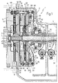
- a vehicle clutch assembly particularly for tractors, is generally indicated by 1 in Figure 1.
- Assembly 1 comprises an elongated outer casing 2 having a first opening closed by a plate 3, and communicating, via a second opening facing the first opening, with the interior of a further casing 4 integral with casing 2 and housing a flywheel 5 connected to the output shaft 6 of an engine (not shown) and defining an axis 7.
- Casing 2 houses two clutches 8 and 9 disposed adjacent to each other along axis 7.
- Clutch 8 is operable to connect flywheel 5 to a first hollow drive shaft 10 extending coaxially with axis 7 through an opening in plate 3, and connected in known manner (not shown) to the input shaft of a transmission (not shown) of the vehicle (not shown).
- Clutch 9 on the other hand is operable to connect flywheel 5 to a second drive shaft 12 extending coaxially with axis 7 inside shaft 10, and projecting outwardly from the distal end of shaft 10 and beyond a casing (not shown) housing the transmission (not shown) so as to define the power take-off of the vehicle (not shown).
- Clutch 8 which is conventional in the art, comprises a hub 13 fitted to an intermediate portion of shaft 10 by means of a splined coupling 14.
- the hub 13 is provided, in angularly fixed manner, with a disk 15, arranged coaxially with axis 7 and provided with respective annular disks 16 of frictional material on the opposite surfaces thereof.
- Clutch 8 also comprises two further disks 17 and 18 on either side of disk 15 and coaxial with axis 7; disk 17 being fixedly connected in known manner (not shown) with flywheel 5 and disk 18 being connected to disk 17 in angularly integral and axially sliding manner by means of a number of pins 19 (only one shown), so as to rotate with, move to and from, and compress disks 15 and 16 against disk 17. More specifically, each pin 19 presents an end portion 20 connected integrally with disk 18 and an opposite end portion 21 engaging in axially sliding manner a respective hole 21a in disk 17, and projecting partially outwardly of disk 17.
- Disk 18 is normally maintained in the forward, operative position (being the right hand direction of Figure 1), corresponding to closure or engagement of clutch 8, by a Belleville spring 23 interposed between disk 18 and an annular stop body 24 integrally connected to disk 17 whereas clutch 8 is opened or released by means of a manually operated control device 25 which is operable to exert a force on disk 18 in opposite direction to the force exerted by spring 23, such as to move disks 18 and 17 apart and move disk 18 into a withdrawn position.
- device 25 comprises a number of radial levers 26 equiangularly spaced on the side 32 of disk 17 facing away from disks 15 and 16, and each presenting a peripheral end portion hinged, by means of a respective pin 27 arranged perpendicularly to axis 7, to a respective peripheral portion of disk 17 adjacent to a respective pin 19, so as to swing about the axis of a respective pin 27.
- each lever 26 hingeably supports an intermediate portion of a rocker arm 29, a first arm 30 of which presenting an end portion contacting the outer surface 32 of disk 17, and the second arm 33 of which presenting an end portion contacting the front surface of portion 21 of a respective pin 19.
- Levers 26 are rotated in relation to disk 17 and about respective pins 27 by a control assembly 34 forming part of the device 25 and comprising a sleeve 35 fitted in axially sliding and angularly fixed manner to an intermediate portion of shaft 10, and supporting a collar 36 which cooperates with the free end portion of levers 26 and is fitted to sleeve 35 via the interposition of a bearing 37 enabling the collar 36 to rotate about axis 7.
- a control assembly 34 forming part of the device 25 and comprising a sleeve 35 fitted in axially sliding and angularly fixed manner to an intermediate portion of shaft 10, and supporting a collar 36 which cooperates with the free end portion of levers 26 and is fitted to sleeve 35 via the interposition of a bearing 37 enabling the collar 36 to rotate about axis 7.
- Sleeve 35 is movable along shaft 10, between a withdrawn, idle position corresponding to closure or engagement of clutch 8, and a forward, operative position corresponding to opening or release of clutch 8, by means of a lever 38 (shown in Figure 2), the intermediate portion of which is hinged to casing 2 so as to rotate, in relation to casing 2, about an axis 39 oriented perpendicularly relative to axis 7.
- Lever 38 comprises a fork 40, the arms 41 of which are connected in known manner to sleeve 35, and an arm 43 connected in known manner to the clutch pedal (not shown) of the tractor preferably by means of a flexible connecting member 45.
- clutch 9 comprises a hub 46 fitted by means of a splined coupling 47 to an intermediate portion of shaft 12 projecting from shaft 10 towards flywheel 5, and fitted in angularly fixed manner with a disk 48 coaxial with axis 7.
- disk 48 is provided, on the opposite surfaces thereof, with respective annular disks 49 of frictional material.
- Clutch 9 further comprises a thrust disk 50 provided coaxially with axis 7 on the opposite side of disks 48 and 49 relative to the flywheel 5, and connected in axially sliding and angularly fixed manner to disk 17 by means of a number of pins 51 (only one shown) so as to compress disks 48 and 49 against a contact surface 53 formed on the side of the flywheel 5 facing in the direction of disks 48, 49 and being provided parallel thereto.
- each pin 51 comprises an end portion 54 integrally connected with disk 50; the end portion 54 in turn having an end portion 55 projecting outwardly of disk 50 towards flywheel 5.
- Each pin 51 further comprises an opposite end portion 56 engaging, in axially sliding manner, respective coaxial holes 57 in disks 17 and 18, and projecting partially outwardly of disk 17.
- Each said end portion 55 of pins 51 is fitted with a respective compression spring 58, one end portion of which is positioned against a shoulder on respective pin 51, and the opposite end portion of which engages a respective axial seat 59 formed in a peripheral portion of flywheel 5.
- the rigidity of springs 58 is such as to normally maintain disk 50 withdrawn from flywheel 5 in a position corresponding to opening or release of clutch 9. It will be appreciated that in the example shown in Figure 1 only little force is needed to move the disk 50 away from the flywheel 5 and therefore the rigidity of the springs 58 may be small.
- the closed or engaged condition of clutch 9 is achieved by moving disk 50 axially towards flywheel 5 by means of a lever control device 62 which is operable to exert a force on disk 50 in a direction opposite to the direction of the force exerted by springs 58.
- Device 62 comprises a number of radial levers 63 which extend on the same side of disk 17 as levers 26 and are angularly offset in relation thereto.
- the design and operation of the levers 63 are comparable to the levers 26. More specifically, a respective peripheral portion of each lever 63 is hinged, by means of a respective pin 64 oriented perpendicularly relative to axis 7, to a respective peripheral portion of disk 17 adjacent to a respective pin 51, enabling each lever 63 to rotate about the axis of an associated pin 64.
- each lever 63 hingeably supports an intermediate portion of a respective rocker arm 66, a first arm 67 of which presenting an end portion contacting the outer surface 32 of disk 17, fixed in relation to the axis of pin 64, and the second arm 68 of which presenting an end portion contacting the front surface of portion 56 of a respective pin 51 which acts as a push rod.
- Levers 63 are rotated in relation to disk 17 and about respective pins 64 by a control assembly 69 forming part of device 62 and comprising a sleeve 70 extending coaxially and outwardly of sleeve 35 and fitted to the outer surface of sleeve 35 in axially sliding and angularly fixed manner.
- Sleeve 70 supports a collar 71 extending outwardly thereof and fitted rotatably but axially fixed relative to sleeve 70 by means of a bearing 71a.
- the collar 71 has a front groove 72 on the side facing clutch 8 in which a ring 73 is housed partially engaging groove 72 in axially sliding and angularly fixed manner.
- the ring 73 is retained inside groove 72 by a retaining ring 74 and presents a front outer surface contacting the free end portions of levers 63 against which ring 73 is forced by a compression spring 75, in this case a Belleville spring, housed inside groove 72.
- spring 75 may be interposed between the outer ring of bearing 71a and an inner radial flange formed integrally with collar 71.
- sleeve 70 is movable along axis 7 and in relation to sleeve 35, between a forward, operative position corresponding to closure or engagement of clutch 9, and a withdrawn, idle position corresponding to opening or release of clutch 9, by means of a rocking lever 76 forming part of assembly 69, located adjacent to lever 38, and having an intermediate portion hinged to casing 2 so as to rotate, in relation to casing 2, about an axis 77 parallel to axis 39.
- Lever 76 comprises on the one hand a fork 78, the arms 79 of which are connected in known manner to sleeve 70, and on the other hand an arm 80 extending on the opposite side of said intermediate portion of lever 76 in relation to fork 78, and connected to a hand-operated lever 81 comprising an angular locking device 82 for locking lever 81 in two given angular positions, only one of which being shown in Figure 2.
- lever 81 is connected to the arm 80 by a flexible connection 83 comprising a sheath 84 extending along a given path P between a fixed point adjacent to lever 81, and a plate 85 fitted integrally with casing 2 and adjacent to the arm 80.
- Sheath 84 houses a cable 86, one end of which is operatively connected with lever 81, and the opposite end of which is operatively connected in a conventional manner with a member 87 connecting cable 86 to arm 80.
- assembly 1 will now be described in more detail, commencing with both sleeves 35 and 70 being located in the withdrawn position (towards the right hand side of Figure 1), whereby clutch 8 is engaged (with disks 15 and 16 compressed against disk 17 by disk 18 and spring 23), and clutch 9 is released (with disk 50 maintained in the withdrawn position by springs 58).
- lever 81 is operated so as to rotate lever 76 anticlockwise (with reference to Figure 2) about axis 77 by means of the connection 83, thereby moving sleeve 70 in relation to shaft 10 and to sleeve 35 into the forward position wherein ring 73 presses on the free ends of the levers 63 and rotates levers 63 about the axes of respective pins 64.
- spring 75 provides for regulating the force with which clutch 9 is engaged, thus ensuring smooth, gradual engagement.
- rocker arms 66 rotate anticlockwise (with reference to Figure 1) about the axes of respective pins 65 so as to move respective pins 51, which in this case act as push rods, towards flywheel 5 together with disk 50.
- springs 58 are gradually compressed and disks 48 and 49 are pressed against flywheel 5 thereby engaging clutch 9, connecting shaft 12 angularly to flywheel 5 and activating the power take-off.
- the spring 75 is operable to withdraw sleeve 70 thereby allowing the pins 51 and the disk 50 to withdraw from the flywheel 5 with the additional help of the spring 58 in order to deactivate the power take-off.
- spring 75 associated with clutch 9 may be replaced, in an alternative arrangement, by an elastic device 88 for setting and maintaining clutch 9 in the open or released position, and, in this case also, for enabling smooth, gradual engagement of clutch 9.
- Device 88 comprises a first sleeve 89, fitted integrally with plate 85 and extending around cable 86 towards the arm 80, and a second sleeve 90 fitted in axially sliding manner to the first sleeve 89 and terminating at opposite ends with respective outer flanges 91 and 92.
- Flange 91 defines a stop member for one end of a set of Belleville washers 93 aligned between flange 91 and plate 85, while flange 92 is arranged to contact a plate 94 in turn contacting an abutment member 95 on member 87.
- the Belleville washers 93 are replaced by an ordinary helical compression spring 96 fitted to sleeve 89 while sleeve 90 is replaced by a cap 97 housing one end of spring 96 and also arranged to contact plate 94.
- the rigidity of the washers 93 and the spring 96 is such as to regulate the force with which clutch 9 is engaged in order to ensure smooth gradual engagement without the occurrence of undesired shocks.
- arm 80 is so operated, via member 87 and by springs 93 or spring 96 via respective sleeve 90 or cap 97, as to rotate lever 76 clockwise (with reference to Figure 2), move sleeve 70 axially in relation to sleeve 35 into the withdrawn position, and so release clutch 9 and deactivate the power take-off as already explained.
- assembly 1 also offers the advantage of safeguarding the operator or any bystanders in the vicinity of the tractor in the event, for example, of inadvertent snapping of the flexible connection between the lever 81 and the arm 80 during operation of the power take-off.
- both spring 75 and device 88 provide for immediately releasing clutch 9 and deactivating the power take-off.
- clutch assembly 1 as described above prevents the power take-off from being activated under any condition other than voluntarily by the operator.
- the present invention offers the further advantage to have the springs 58 and 75 or 88 in a non-compressed condition for most of the time thereby increasing the lifetime thereof.
Claims (14)
- Ensemble d'embrayage (1) pour véhicule, plus particulièrement pour tracteurs, comprenant:caractérisé en ce que l'nsemble d'embrayage (1) comprend en outre un second moyen (75/88) élastique mis sous tension lorsque le second embrayage (9) est contraint vers la position engagée en contrôlant de cette façon la force avec laquelle le second embrayage (9) est engagé.un premier embrayage (8) interposé entre un arbre d'entraínement (6) du moteur et une transmission du véhicule; etun second embrayage (9) interposé entre ledit arbre d'entraínement (6) et un arbre de sortie (12) définissant la prise de force du véhicule; ledit second embrayage (9) pouvant être déplacé vers une position engagée dans laquelle ledit arbre de sortie (12) est accouplé fonctionnellement audit arbre d'entraínement (6) et comprenant un premier moyen élastique (58) dont la fonction est de contraindre ledit second embrayage (9) vers une position dégagée dans laquelle ledit arbre de sortie (12) est débrayé fonctionnellement dudit arbre d'entraínement (6); et
- Ensemble selon la revendication 1 caractérisé en ce que l'ensemble comprend en outre un moyen (51, 62, 81) d'activation actionné manuellement pour commander ledit second embrayage (9), en exerçant une force dans une direction opposée à la direction de la force exercée par lesdits premier et second moyens (58, 75/88) élastiques et en contraignant le second embrayage (9) vers une position engagée dans laquelle lesdits arbres (6, 12) sont accouplés suivant un angle.
- Ensemble selon la revendication 2, caractérisé en ce que la fonction dudit second moyen (75/88) élastique, en association avec ledit premier moyen (58) élastique, est d'assister activement le dégagement dudit second embrayage (9) lorsque ledit moyen (51, 62, 81) d'activation est intentionnellement ou involontairement ramené vers une position dégagée.
- Ensemble selon l'une quelconque des revendications précédentes, caractérisé en ce que ledit second embrayage (9) comprend un premier corps (5) de disque et un second corps (50) de disque pouvant tourner autour d'une axe (7) commun et déplaçables axialement l'un par rapport à l'autre afin d'engager un disque (48, 49) de friction; ledit moyen (51, 62, 83, 81) d'activation comprenant:plusieurs tiges-poussoirs (51) afin de déplacer lesdits premier (5) et second (50) corps de disque l'un vers l'autre;un système (62) pour actionner lesdites tiges-poussoirs (51); etun premier levier (81) actionné manuellement pour contrôler ledit système (62) d'activation; ledit système (62) d'activation comprenant ledit second moyen (75) élastique.
- Ensemble selon la revendication 4, caractérisé en ce que ledit moyen (62) d'activation comprend plusieurs leviers (63) pouvant pivoter autour des premiers axes (64) respectifs perpendiculaires à l'axe (7) desdits corps (5, 50) et un collet (71) de butée déplaçable coaxialement avec ledit axe (7), afin de faire pivoter lesdits seconds leviers (63) autour desdits premiers axes (64) respectifs; ledit second moyen (75) élastique étant interposé entre lesdits seconds leviers (63) et ledit collet (71) de butée.
- Ensemble selon l'une quelconque des revendications précédentes, caractérisé en ce que ledit second moyen (75) élastique comprend au moins un ressort (75) de compression.
- Ensemble selon les revendications 1 à 3, caractérisé en ce que ledit second embrayage (9) comprend un premier corps (5) de disque et un second corps (50) de disque pouvant tourner autour d'un axe (7) commun, et déplaçables axialement l'un par rapport à l'autre afin d'engager un disque (48, 49) de friction; ledit moyen d'activation (51, 62, 83, 81) comprenant:plusieurs tiges-poussoirs (51) afin de déplacer lesdits premier (5) et second (50) corps de disque l'un vers l'autre;un système (62) pour actionner lesdites tiges-poussoirs (51); etun premier levier (81) commandé manuellement pour contrôler ledit système (62) d'activation; ledit second moyen (88) élastique étant interposé entre ledit système (62) d'activation et ledit premier levier (81).
- Ensemble selon la revendication 7, caractérisé en ce que ledit système (62) d'activation comprend plusieurs seconds leviers (63) pivotables autour des premiers axes (64) respectifs perpendiculaires à l'axe (7) desdits corps (5, 50), un collet (71) de butée déplaçable coaxialement avec ledit axe (7) afin de faire pivoter lesdits seconds leviers (63) autour desdits premiers axes (64) respectifs et un troisième levier (76) pour activer ledit collet (71); ledit second moyen élastique (88) étant interposé entre le premier levier (81) et le troisième levier (76).
- Ensemble selon la revendication 8, caractérisé en ce que ledit moyen (51, 62, 83, 81) d'activation comprend en outre un organe (83) de liaison reliant ledit premier levier (81) audit troisième levier (76); ledit second moyen (88) élastique étant situé le long du parcours (P) dudit organe (83) de liaison entre une butée fixe (85) et ledit premier levier (81) ou ledit troisième levier (76).
- Ensemble selon l'une quelconque des revendications 7 à 9, caractérisé en ce que ledit second moyen élastique comprend plusieurs rondelles Belleville (93).
- Ensemble selon l'une quelconque des revendications 7 à 9, caractérisé en ce que ledit second moyen élastique comprend un ressort (96) hélicoïdal de compression.
- Ensemble selon l'une quelconque des revendications 4 à 11, caractérisé en ce que ledit système (62) d'activation comprend en outre plusieurs culbuteurs (66), chacun monté sur undit second levier (63) respectif, et chacun comprenant une partie intermédiaire reliée audit second levier (63) respectif et pivotant par rapport à lui, et un premier bras (67) entrant en contact avec une surface (32) fixe par rapport auxdits premiers axes (64); chaque culbuteur (66) comprenant également un second bras (68) s'associant avec l'extrémité (56) d'unedite tige-poussoir (51) respective.
- Ensemble selon l'une quelconque des revendications 4 et 7 et l'une quelconque des revendications s'y rapportant, caractérisé en ce qu'il comprend un moyen (82) de blocage angulaire pour maintenir amoviblement ledit premier levier (81) dans deux positions angulaires données.
- Ensemble selon l'une quelconque des revendications précédentes, caractérisé en ce que ledit premier moyen (58) élastique est moins rigide que ledit second moyen (75/ 88) élastique.
Applications Claiming Priority (2)
| Application Number | Priority Date | Filing Date | Title |
|---|---|---|---|
| ITTO930408A IT1270456B (it) | 1993-06-07 | 1993-06-07 | Gruppo frizione per veicoli, in particolare macchine trattrici |
| ITTO930408 | 1993-06-07 |
Publications (2)
| Publication Number | Publication Date |
|---|---|
| EP0628741A1 EP0628741A1 (fr) | 1994-12-14 |
| EP0628741B1 true EP0628741B1 (fr) | 1999-08-11 |
Family
ID=11411542
Family Applications (1)
| Application Number | Title | Priority Date | Filing Date |
|---|---|---|---|
| EP94201414A Expired - Lifetime EP0628741B1 (fr) | 1993-06-07 | 1994-05-19 | Ensemble d'accouplement de véhicule, notamment pour tracteurs |
Country Status (4)
| Country | Link |
|---|---|
| US (1) | US5513734A (fr) |
| EP (1) | EP0628741B1 (fr) |
| DE (1) | DE69419976T2 (fr) |
| IT (1) | IT1270456B (fr) |
Families Citing this family (12)
| Publication number | Priority date | Publication date | Assignee | Title |
|---|---|---|---|---|
| IT1273057B (it) * | 1994-08-03 | 1997-07-01 | Carraro Spa | Gruppo di innesto a frizione |
| US6012561A (en) * | 1998-09-15 | 2000-01-11 | Chrysler Corporation | Dual clutch design for and electro-mechanical automatic transmission having a dual input shaft |
| DE10036675B4 (de) * | 2000-07-27 | 2012-05-03 | Zf Friedrichshafen Ag | Ausrückeranordnung für eine Doppelkupplungsanordnung |
| AU2003222727A1 (en) * | 2002-03-27 | 2003-10-08 | Luk Lamellen Und Kupplungsbau Beteiligungs Kg | Twin clutch system for a transmission, particularly for a twin clutch transmission |
| US7234366B2 (en) * | 2004-03-26 | 2007-06-26 | Cnh America Llc | Power take-off control system |
| US7234367B2 (en) * | 2004-03-26 | 2007-06-26 | Cnh America Llc | Power take-off control system |
| US7048106B2 (en) * | 2004-03-26 | 2006-05-23 | Cnh America Llc | Power take-off control system and method |
| US7204166B2 (en) * | 2004-11-08 | 2007-04-17 | Eaton Corporation | Dual clutch assembly for a heavy-duty automotive powertrain |
| WO2006084435A1 (fr) * | 2005-02-11 | 2006-08-17 | Luk Lamellen Und Kupplungsbau Beteiligungs Kg | Unite d'embrayage |
| DE102007022422A1 (de) * | 2007-05-10 | 2008-11-13 | Borgwarner Inc., Auburn Hills | Doppelkupplungsanordnung mit Kolbenführungselement |
| DE102009013973B4 (de) * | 2008-04-04 | 2022-02-17 | Schaeffler Technologies AG & Co. KG | Kupplungseinrichtung |
| JP6621959B1 (ja) * | 2019-08-09 | 2019-12-18 | 株式会社クボタ | 作業車両 |
Family Cites Families (13)
| Publication number | Priority date | Publication date | Assignee | Title |
|---|---|---|---|---|
| US2259730A (en) * | 1938-02-02 | 1941-10-21 | Edith Glynn Burtnett | Multiclutch mechanism |
| US2613778A (en) * | 1944-12-07 | 1952-10-14 | Borg Warner | Multiple friction clutch |
| DE1505577A1 (de) * | 1966-05-04 | 1970-07-23 | Bosch Gmbh Robert | Kupplungsvorrichtung |
| GB1392299A (en) * | 1971-09-18 | 1975-04-30 | Gkn Transmissions Ltd | Clutches |
| US3760918A (en) * | 1972-04-20 | 1973-09-25 | Deere & Co | Tractor pto and propulsion clutch assembly including lubrication means |
| GB1537704A (en) * | 1976-02-14 | 1979-01-04 | Brown Tractors Ltd | Clutches |
| FR2374557A1 (fr) * | 1976-12-16 | 1978-07-13 | Ferodo Sa | Embrayage a double disque de friction |
| FR2397563A1 (fr) * | 1977-07-13 | 1979-02-09 | Ferodo Sa | Embrayage a deux disques de friction et mecanisme propre a la constitution d'un tel embrayage |
| FR2441762A1 (fr) * | 1978-11-17 | 1980-06-13 | Ferodo Sa | Embrayage a deux sorties |
| FR2461845A1 (fr) * | 1979-07-24 | 1981-02-06 | Citroen Sa | Dispositif de commande mecanique d'embrayage |
| FR2544036B1 (fr) * | 1983-04-11 | 1988-10-28 | Valeo | Piece d'accostage a rapporter sur le diaphragme d'un embrayage, et ensemble unitaire constitue par un tel diaphragme et une telle piece d'accostage |
| IT1161190B (it) * | 1983-04-27 | 1987-03-11 | Baruffaldi Frizioni Spa | Dispositivo di innesto a frizione elettromagnetica con disinnesto automatico particolarmente per prese di forza ausiliare di macchine agricole |
| DE3446460A1 (de) * | 1984-12-20 | 1986-07-03 | Dr.Ing.H.C. F. Porsche Ag, 7000 Stuttgart | Doppelkupplung fuer ein kraftfahrzeuggetriebe |
-
1993
- 1993-06-07 IT ITTO930408A patent/IT1270456B/it active IP Right Grant
-
1994
- 1994-05-19 DE DE69419976T patent/DE69419976T2/de not_active Expired - Lifetime
- 1994-05-19 EP EP94201414A patent/EP0628741B1/fr not_active Expired - Lifetime
- 1994-06-03 US US08/254,019 patent/US5513734A/en not_active Expired - Lifetime
Also Published As
| Publication number | Publication date |
|---|---|
| US5513734A (en) | 1996-05-07 |
| DE69419976T2 (de) | 1999-12-23 |
| ITTO930408A1 (it) | 1994-12-07 |
| EP0628741A1 (fr) | 1994-12-14 |
| IT1270456B (it) | 1997-05-05 |
| DE69419976D1 (de) | 1999-09-16 |
| ITTO930408A0 (it) | 1993-06-07 |
Similar Documents
| Publication | Publication Date | Title |
|---|---|---|
| EP0628741B1 (fr) | Ensemble d'accouplement de véhicule, notamment pour tracteurs | |
| US4671400A (en) | Wear take-up assembly for the actuating arrangement of a coupling device such as a clutch | |
| US4667459A (en) | Two action control for power mowers | |
| JP3559096B2 (ja) | リニア・アクチュエータ | |
| GB2277358A (en) | Clutch/brake combination | |
| JP2000213555A (ja) | クラッチリング用アクチュエ―タ | |
| US4760906A (en) | Internal assisted clutch | |
| US4744450A (en) | Device for maintaining a clutch release bearing in contact with a clutch cover assembly at all times | |
| US4418811A (en) | Clutch with fail-safe helical spring | |
| US4393965A (en) | Rotary actuator | |
| JPH02146318A (ja) | クラッチ用解放機構 | |
| US4393907A (en) | Clutch assist apparatus | |
| US20220290744A1 (en) | Linear actuator | |
| US5769362A (en) | Aircraft control mechanism for a speed brake | |
| US3018863A (en) | Friction clutch mechanism | |
| US4330054A (en) | Amplifying clutch with radially contractible shoe | |
| JP2616598B2 (ja) | モータ式アクチュエータ | |
| US5415059A (en) | Turf machine lockable brake mechanism | |
| US6460670B2 (en) | Clutch for blade engagement | |
| USRE34105E (en) | Internal assisted clutch | |
| EP0290940B1 (fr) | Embrayage à assistance interne | |
| GB2073352A (en) | Device for the automatic readjustment of an actuating mechanism during wear of a vehicle clutch | |
| US20030049070A1 (en) | Drive assembly, especially for agricultural implements | |
| US5067602A (en) | Internally assisted clutch | |
| US2379024A (en) | Two-way clutch |
Legal Events
| Date | Code | Title | Description |
|---|---|---|---|
| PUAI | Public reference made under article 153(3) epc to a published international application that has entered the european phase |
Free format text: ORIGINAL CODE: 0009012 |
|
| AK | Designated contracting states |
Kind code of ref document: A1 Designated state(s): DE ES FR GB IT |
|
| 17P | Request for examination filed |
Effective date: 19950516 |
|
| RAP1 | Party data changed (applicant data changed or rights of an application transferred) |
Owner name: NEW HOLLAND ITALIA S.P.A. |
|
| 17Q | First examination report despatched |
Effective date: 19960112 |
|
| GRAG | Despatch of communication of intention to grant |
Free format text: ORIGINAL CODE: EPIDOS AGRA |
|
| GRAG | Despatch of communication of intention to grant |
Free format text: ORIGINAL CODE: EPIDOS AGRA |
|
| GRAG | Despatch of communication of intention to grant |
Free format text: ORIGINAL CODE: EPIDOS AGRA |
|
| GRAG | Despatch of communication of intention to grant |
Free format text: ORIGINAL CODE: EPIDOS AGRA |
|
| GRAH | Despatch of communication of intention to grant a patent |
Free format text: ORIGINAL CODE: EPIDOS IGRA |
|
| GRAH | Despatch of communication of intention to grant a patent |
Free format text: ORIGINAL CODE: EPIDOS IGRA |
|
| GRAA | (expected) grant |
Free format text: ORIGINAL CODE: 0009210 |
|
| AK | Designated contracting states |
Kind code of ref document: B1 Designated state(s): DE ES FR GB IT |
|
| PG25 | Lapsed in a contracting state [announced via postgrant information from national office to epo] |
Ref country code: ES Free format text: THE PATENT HAS BEEN ANNULLED BY A DECISION OF A NATIONAL AUTHORITY Effective date: 19990811 |
|
| REF | Corresponds to: |
Ref document number: 69419976 Country of ref document: DE Date of ref document: 19990916 |
|
| ET | Fr: translation filed | ||
| ITF | It: translation for a ep patent filed |
Owner name: STUDIO TORTA S.R.L. |
|
| PLBE | No opposition filed within time limit |
Free format text: ORIGINAL CODE: 0009261 |
|
| STAA | Information on the status of an ep patent application or granted ep patent |
Free format text: STATUS: NO OPPOSITION FILED WITHIN TIME LIMIT |
|
| 26N | No opposition filed | ||
| REG | Reference to a national code |
Ref country code: GB Ref legal event code: IF02 |
|
| REG | Reference to a national code |
Ref country code: FR Ref legal event code: CD |
|
| PGFP | Annual fee paid to national office [announced via postgrant information from national office to epo] |
Ref country code: IT Payment date: 20110524 Year of fee payment: 18 |
|
| PGFP | Annual fee paid to national office [announced via postgrant information from national office to epo] |
Ref country code: DE Payment date: 20120410 Year of fee payment: 19 |
|
| PGFP | Annual fee paid to national office [announced via postgrant information from national office to epo] |
Ref country code: GB Payment date: 20120410 Year of fee payment: 19 Ref country code: FR Payment date: 20120423 Year of fee payment: 19 |
|
| PG25 | Lapsed in a contracting state [announced via postgrant information from national office to epo] |
Ref country code: IT Free format text: LAPSE BECAUSE OF NON-PAYMENT OF DUE FEES Effective date: 20120519 |
|
| GBPC | Gb: european patent ceased through non-payment of renewal fee |
Effective date: 20130519 |
|
| PG25 | Lapsed in a contracting state [announced via postgrant information from national office to epo] |
Ref country code: DE Free format text: LAPSE BECAUSE OF NON-PAYMENT OF DUE FEES Effective date: 20131203 |
|
| REG | Reference to a national code |
Ref country code: DE Ref legal event code: R119 Ref document number: 69419976 Country of ref document: DE Effective date: 20131203 |
|
| REG | Reference to a national code |
Ref country code: FR Ref legal event code: ST Effective date: 20140131 |
|
| PG25 | Lapsed in a contracting state [announced via postgrant information from national office to epo] |
Ref country code: GB Free format text: LAPSE BECAUSE OF NON-PAYMENT OF DUE FEES Effective date: 20130519 |
|
| PG25 | Lapsed in a contracting state [announced via postgrant information from national office to epo] |
Ref country code: FR Free format text: LAPSE BECAUSE OF NON-PAYMENT OF DUE FEES Effective date: 20130531 |