EP0627293A1 - Formdüse für scheibenlüfter und verfahren zur herstellung von scheibenlüftern unter verwendung dieser düse - Google Patents
Formdüse für scheibenlüfter und verfahren zur herstellung von scheibenlüftern unter verwendung dieser düse Download PDFInfo
- Publication number
- EP0627293A1 EP0627293A1 EP93921110A EP93921110A EP0627293A1 EP 0627293 A1 EP0627293 A1 EP 0627293A1 EP 93921110 A EP93921110 A EP 93921110A EP 93921110 A EP93921110 A EP 93921110A EP 0627293 A1 EP0627293 A1 EP 0627293A1
- Authority
- EP
- European Patent Office
- Prior art keywords
- blades
- circular plate
- molding
- core
- stacked
- Prior art date
- Legal status (The legal status is an assumption and is not a legal conclusion. Google has not performed a legal analysis and makes no representation as to the accuracy of the status listed.)
- Withdrawn
Links
- 238000000465 moulding Methods 0.000 title claims abstract description 253
- 238000004519 manufacturing process Methods 0.000 title claims abstract description 40
- 239000011347 resin Substances 0.000 claims abstract description 238
- 229920005989 resin Polymers 0.000 claims abstract description 238
- 125000006850 spacer group Chemical group 0.000 claims description 42
- 230000002093 peripheral effect Effects 0.000 claims description 39
- 238000004891 communication Methods 0.000 claims description 11
- 238000010008 shearing Methods 0.000 claims description 7
- 238000002347 injection Methods 0.000 description 31
- 239000007924 injection Substances 0.000 description 31
- 238000000034 method Methods 0.000 description 30
- 238000010276 construction Methods 0.000 description 23
- 230000003028 elevating effect Effects 0.000 description 8
- 238000010438 heat treatment Methods 0.000 description 8
- 239000000047 product Substances 0.000 description 7
- 230000007246 mechanism Effects 0.000 description 5
- 238000005204 segregation Methods 0.000 description 5
- 230000003247 decreasing effect Effects 0.000 description 4
- 230000006872 improvement Effects 0.000 description 4
- 230000001105 regulatory effect Effects 0.000 description 4
- 238000005520 cutting process Methods 0.000 description 3
- 239000012530 fluid Substances 0.000 description 3
- 238000012423 maintenance Methods 0.000 description 3
- 230000007423 decrease Effects 0.000 description 2
- 230000002542 deteriorative effect Effects 0.000 description 2
- 210000003414 extremity Anatomy 0.000 description 2
- 230000002349 favourable effect Effects 0.000 description 2
- 239000012467 final product Substances 0.000 description 2
- 230000005484 gravity Effects 0.000 description 2
- 238000001746 injection moulding Methods 0.000 description 2
- 230000004048 modification Effects 0.000 description 2
- 238000012986 modification Methods 0.000 description 2
- 230000002035 prolonged effect Effects 0.000 description 2
- 231100000241 scar Toxicity 0.000 description 2
- 208000032544 Cicatrix Diseases 0.000 description 1
- 238000004140 cleaning Methods 0.000 description 1
- 230000005415 magnetization Effects 0.000 description 1
- 239000000463 material Substances 0.000 description 1
- 230000037387 scars Effects 0.000 description 1
- 238000007711 solidification Methods 0.000 description 1
- 230000008023 solidification Effects 0.000 description 1
- 210000001364 upper extremity Anatomy 0.000 description 1
- 239000002699 waste material Substances 0.000 description 1
- XLYOFNOQVPJJNP-UHFFFAOYSA-N water Substances O XLYOFNOQVPJJNP-UHFFFAOYSA-N 0.000 description 1
- 238000003466 welding Methods 0.000 description 1
Images













Classifications
-
- B—PERFORMING OPERATIONS; TRANSPORTING
- B29—WORKING OF PLASTICS; WORKING OF SUBSTANCES IN A PLASTIC STATE IN GENERAL
- B29C—SHAPING OR JOINING OF PLASTICS; SHAPING OF MATERIAL IN A PLASTIC STATE, NOT OTHERWISE PROVIDED FOR; AFTER-TREATMENT OF THE SHAPED PRODUCTS, e.g. REPAIRING
- B29C45/00—Injection moulding, i.e. forcing the required volume of moulding material through a nozzle into a closed mould; Apparatus therefor
- B29C45/17—Component parts, details or accessories; Auxiliary operations
- B29C45/26—Moulds
- B29C45/33—Moulds having transversely, e.g. radially, movable mould parts
-
- B—PERFORMING OPERATIONS; TRANSPORTING
- B29—WORKING OF PLASTICS; WORKING OF SUBSTANCES IN A PLASTIC STATE IN GENERAL
- B29C—SHAPING OR JOINING OF PLASTICS; SHAPING OF MATERIAL IN A PLASTIC STATE, NOT OTHERWISE PROVIDED FOR; AFTER-TREATMENT OF THE SHAPED PRODUCTS, e.g. REPAIRING
- B29C45/00—Injection moulding, i.e. forcing the required volume of moulding material through a nozzle into a closed mould; Apparatus therefor
- B29C45/17—Component parts, details or accessories; Auxiliary operations
- B29C45/40—Removing or ejecting moulded articles
- B29C45/44—Removing or ejecting moulded articles for undercut articles
- B29C45/4421—Removing or ejecting moulded articles for undercut articles using expansible or collapsible cores
-
- B—PERFORMING OPERATIONS; TRANSPORTING
- B29—WORKING OF PLASTICS; WORKING OF SUBSTANCES IN A PLASTIC STATE IN GENERAL
- B29L—INDEXING SCHEME ASSOCIATED WITH SUBCLASS B29C, RELATING TO PARTICULAR ARTICLES
- B29L2031/00—Other particular articles
- B29L2031/08—Blades for rotors, stators, fans, turbines or the like, e.g. screw propellers
- B29L2031/087—Propellers
Definitions
- the present invention relates to a mold for molding a multi-stacked circular plate fan which is capable of producing a precise multi-stacked circular plate fan made of a multiplicity of fine and thin circular plates and a method for producing a multi-stacked circular plate fan using the above mold.
- the fan means any fan which is applicable to various fluid machines for carrying out the treatment of a fluid such as air or water.
- the fluid machine is a concept which includes an air fan, a blower fan, a pump and a compressor.
- a fan structure called a multi-stacked circular plate fan.
- the fan is made by stacking a multiplicity of thin circular plates with a fine gap therebetween and is featured by its excellent fan characteristic, namely, its extremely silent rotation during a fan operation.
- a multiplicity of thin annular circular plates 304 are stacked on a circular mounting plate 306 with a desired gap to provide a multi-stacked circular plate fan F.
- the multi-stacked circular plate fan F produced in this manner can be used, for example, in a following way.
- the multi-stacked circular plate fan F is connected to the output shaft of a power-operated motor 300 mounted on one side of a fan casing 110 by way of a mounting plate which forms a part of the fan.
- the multi-stacked circular plate fan F is encased in a fan casing 310 which is provided with an air inlet opening at a portion thereof which faces a central hollow portion of the multi-stacked circular plate fan F and an air outlet opening at a side portion of the multi-stacked circular plate fan F.
- the multi-stacked circular plate fan F Since the multi-stacked circular plate fan F generates an air flow making use of a centrifugal force of air generated by a shearing force caused by a rotation of annular thin circular plates 304, the fan operation becomes extremely silent. Furthermore, by interposing a multiplicity of spacers between annular circular plates 304 in a circumferentially spaced apart manner, the blow-off amount of air can be increased.
- the manufacturing of the multi-stacked circular plate fan F has several problems. Namely, a multiplicity of annular circular plates 304 and a multiplicity of spacers 305 which act as air regulating vanes are prepared as separate elements independently.
- the spacers 305 are interposed between the annular circular plates 304 and thereafter they are pierced by a plurality of connecting pins 307 and fastened integrally in a stacked manner.
- the above manufacturing method has drawbacks such that it necessitates a manual operation which results in a poor efficiency and a high manufacturing cost. Furthermore, thinner the thickness of the annular circular plates 304, the circular plate assembling operation becomes more cumbersome or difficult in terms of assembling technique.
- Japanese Laid-Open Patent Publication HEI-2-248214 discloses a method for molding a fan while other references discloses techniques for molding other articles other than fan.
- Japanese Laid-Open Patent Publication HEI-2-248214 relates to a mold for molding a cross-flow fan used especially in air conditioners.
- the fan comprises a multiplicity of blade-like thin plates parallely extended between annular circular plates which form ribs and these thin plates are directed radially.
- the fan is provided with a considerably wide space or gap between the annular circular plates so that the fan structure is completely different from the multi-stacked circular plate fan which this invention aims at. Accordingly, the molding technique disclosed in this reference is not available as a molding technique for molding the multi-stacked circular plate fan.
- Japanese Laid-Open Patent Publication HEI-2-212112 is concerned with a technique on a mold for molding a bobbin, wherein the bobbin having a multiplicity of stacked annular circular plates is integrally molded by means of inner and outer core members.
- This reference discloses, in this respect, the technique closest to the mold technique of this invention for molding a multi-stacked circular plate fan.
- the publication discloses the mold for producing the bobbin, but an air blow fan. Therefore, this mold is also constructed such that thin plates have their outer peripheral portions open while a support strut is formed at the core portion of the mold. Accordingly, the molded article can only has its outer peripheral portion open-ended. Namely, the mold technique has a drawback that it cannot mold a stacked body of this invention which is made of circular plates having both inner and outer peripheries thereof open-ended.
- the first invention discloses a mold for molding a multi-stacked circular plate fan which is characterized in that a resin mold for molding the multi-stacked circular plate fan is made of an inner core and an outer core which are separated from each other, that at least either of the inner core or the outer core is provided with a multiplicity of thin blades stacked with a desired narrow gap and communication holes for resin inflow which are formed in the respective blades, and that the gap between the blades corresponds to a thickness of the circular plate of the multi-stacked circular plate fan to be molded and the thickness of the blade corresponds to the gap between the circular plates of the multi-stacked circular plate fan to be molded.
- the first invention is also characterized in that the mold is constructed as follows.
- the second invention discloses a mold for molding a multi-stacked circular plate fan which is characterized in that an outer core which is formed in an annular shape is disposed around an inner core, that a multiplicity of annular thin blades have proximal portions thereof securedly stacked to the inner peripheral surface of the outer core with a narrow gap between blades by means of gap retainers thus forming circular plate fan molding spaces between blades, that a multiplicity of thin retainer plates which are capable of retaining the distal ends of the blades are mounted on the outer peripheral surface of the inner core with a gap between retainer plates by means of gap retainers, that outer core is made of a plurality of separable core units which are slidable radially toward or away from the inner core and capable of forming the outer core in an assembled condition, that gate means for injecting resin into the respective circular plate fan molding spaces in a direction approximately parallel to the blades is provided at a fixed portion of stacked blades of respective core units, that recesses are formed in separating surfaces of the respective blades and these
- the third invention discloses a mold for producing a multi-stacked circular plate fan characterized in that an outer core is disposed around an inner core, that an inner molding surface is formed by providing a plurality of first horizontal grooves and second longitudinal communicating grooves on the inner surface of the outer core, that the inner core is made of an expandible and shrinkable collapsible core, that an outer molding surface is formed by providing a plurality of second horizontal grooves and first longitudinal communicating grooves on the inner surface of the outer core, that the first horizontal grooves and second horizontal grooves are combined to define circular plate fan molding spaces while the first longitudinal communicating grooves and the second longitudinal communicating grooves are combined to define communicating holes for resin inflow, whereby a multi-stacked circular plate fan can be integrally molded.
- the fourth invention discloses a method for producing a multi-stacked circular plate fan comprising following steps;
- the second step b) of the fourth invention can be replaced with a step in which communicating holes for resin inflow are formed in a multiplicity of blades formed at least either of the outer core or the inner core and the resin is injected through the communicating holes for resin inflow into the gaps formed between blades and the communicating holes for resin inflow.
- the inner core and the outer core which are separate from each other are assembled to form a mold for molding a multi-stacked circular plate fan. Due to this assembling operation, gaps for molding circular plates of the multi-stacked circular plate are defined, while these gaps formed between the circular plates are communicated by way of communicating holes for resin inflow formed in the blades. Thereafter, with an injection molding, resin is integrally injected into the communicating holes in resin inflow as well as the circular plate fan molding spaces and hardened. When the resin is sufficiently solidified, the inner core and the outer core are separated from each other so as to separate the blades from an molded article.
- a multi-stacked circular plate fan provided with circular plates which has both inner and outer peripheral portions thereof open-ended as well as spacers can be molded (refer to claim 1).
- the blades are stacked with a narrow gap between blades by means of gap retainers interposed at the proximal portions of the blades (refer to claim 10).
- the distal ends of the blades mounted on either of the inner core or the outer core come into contact with the retaining portion of either of the inner core or the outer core on which blades are not mounted (refer to claim 8) so that the outer periphery of the inner core come into contact with the inner periphery of the outer core (refer to claim 2).
- the retaining portion of the either of the inner core or the outer annular mold can be made of a multiplicity of retainer plates which are formed as separate elements from each other (refer to claim 14).
- the retainer portion may be obviated (refer to claim 15).
- either of the inner core or the outer core can be made of a plurality of core units and these core units are slid radially to be assembled (refer to claim 3 and claim 13).
- the recesses formed in the separate surfaces of the blades of the core units are combined with the recesses formed in the separate surfaces of neighboring blades to form communicating holes for resin inflow which work as spacer molding portions (refer to claim 12).
- a mold for molding a multi-stacked circular plate fan which is provided with annular-circular-plate-shaped blades and communicating holes for resin inflow which work as spacer molding space can be formed.
- resin can be injected from the communicating holes for resin inflow to the respective gaps formed between blades and spacer molding spaces in a direction perpendicular to the communicating holes for resin inflow (refer to claim 4).
- resin can be injected from gates which are formed respectively corresponding to most of the circular plate molding spaces (refer to claim 6).
- a fixed-side portion is provided at the proximal ends of the blades and resin can be injected from the fixed-side portion (refer to claim 7) and resin is injected into the gaps in a direction approximately parallel to the blades (refer to claim 5).
- a gate can be formed in a retainer-side portion of the inner core which is provided for retaining the distal ends of the blades and resin is injected from the gate and is filled in the gap between blades and spacer molding spaces (refer to claim 9).
- the core units of either the inner core or the outer core are slid radially so as to remove a multi-stacked circular plate fan as the molded article.
- the mold is provided with blades for forming circular plates on both the inner core and the outer core and the inner core is made of a collapsible core, for removing a molded article, the inner core is shrinked to remove the inner core from the molded article and the core units of the outer core are slid outwardly to remove the outer annular mold from the molded article thus producing a multi-stacked circular plate fan (refer to claim 11).
- Fig. 1 is a longitudinal cross-sectional view of a mold for molding a multi-stacked circular plate fan of the first embodiment according to this invention.
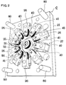
- Fig. 2 is a perspective view of the substantial part of the mold.
- Fig. 3 is a plan view of the substantial part of the mold.
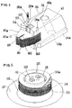
- Fig. 4 is a perspective view of the outer core unit.
- Fig. 5 is a perspective view of an inner core.
- Fig. 6 is an enlarged cross-sectional side view of the mold showing an assembled body of the inner core and the core units.
- Fig. 7 is an enlarged cross-sectional side view of the mold showing the assembled body made of the inner core and the core units.
- Fig. 8 is an explanatory view showing steps of the method for producing a multi-stacked circular plate fan.
- Fig. 9 is a plan view with a part broken away of an assembled body of the inner core and core units in a step 1 of the method for producing a multi-stacked circular plate fan.
- Fig. 10 is an enlarged plan view of the assembled body.
- Fig. 11 is a fragmentary perspective view of blades and blade retaining rings.
- Fig. 12 is an explanatory view showing the manner of removing a runner R in a step 2 of the method for producing a multi-stacked circular plate fan.
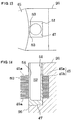
- Fig. 13 is an enlarged plan view of a gate block.
- Fig. 14 is an enlarged cross-sectional side view of the gate block.
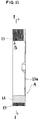
- Fig. 15 is a cross-sectional view of a multi-stacked circular plate fan produced by the mold for producing a multi-stacked circular plate fan according to this embodiment.
- Fig. 16 is a cross-sectional view of the multi-stacked circular plate fan in an arrow direction taken along a line I - I of Fig. 15.
- Fig. 17 is an explanatory view showing a modification of manner of injecting resin.
- Fig. 18 is an explanatory view showing a modification of manner of injecting resin.
- Fig. 19 is a plan view of an improvement of the mold for molding a multi-stacked circular plate fan of the embodiment 1.
- Fig. 20 is an enlarged explanatory view of an essential part of the mold.
- Fig. 21 is a plan view of a multi-stacked circular plate fan produced by the mold for molding a multi-stacked circular plate fan.
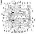
- Fig. 22 is a longitudinal cross-sectional view of a mold for molding a multi-stacked circular plate fan of the second embodiment 2.
- Fig. 23 is a transverse cross-sectional view of the mold taken along the line II - II of Fig. 22.
- Fig. 24 is an explanatory view of the essential part of the mold in Fig. 23.
- Fig. 25 is a fragmentary perspective view of the inner core.
- Fig. 26 is a step of a method for producing a multi-stacked circular plate fan.
- Fig. 27 is a step of a method for producing a multi-stacked circular plate fan.
- Fig. 28 is a step of a method for producing a multi-stacked circular plate fan.
- Fig. 29 is a step of a method for producing a multi-stacked circular plate fan.
- Fig. 30 is a step of a method for producing a multi-stacked circular plate fan.
- Fig. 31 is a step of a method for producing a multi-stacked circular plate fan.
- Fig. 32 is a step of a method for producing a multi-stacked circular plate fan.
- Fig. 33 is a step of a method for producing a multi-stacked circular plate fan.
- Fig. 34 is a step of a method for producing a multi-stacked circular plate fan.
- Fig. 35 is a step of a method for producing a multi-stacked circular plate fan.
- Fig. 36 is a step of a method for producing a multi-stacked circular plate fan.
- Fig. 37 is a step of a method for producing a multi-stacked circular plate fan.
- Fig. 38 is a step of a method for producing a multi-stacked circular plate fan.
- Fig. 39 is a plan view of a multi-stacked circular plate fan produced by a mold for molding a multi-stacked circular plate fan.
- Fig. 40 is a longitudinal cross-sectional view of the mold for producing a multi-stacked circular plate fan showing the essential part of the embodiment.
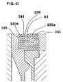
- Fig. 41 is an enlarged explanatory view of the mold.
- Fig. 42 is a cross-sectional view taken along the line III - III of Fig. 40.
- Fig. 43 is a fragmentary perspective view of an inner core.
- Fig. 44 is an explanatory view showing a step of method for producing a multi-stacked circular plate fan with a mold for producing a multi-stacked circular plate fan.
- Fig. 45 is a longitudinal cross-sectional view of a blower provided with a conventional multi-stacked circular plate fan.
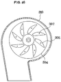
- Fig. 46 is a cross-sectional view taken along the line IV - IV of Fig. 45.
- the mold is for molding a multi-stacked circular plate fan which can be used as an air blower fan.
- numeral 13a indicates a mounting plate forming a part of the multi-stacked circular plate fan A.
- the above-mentioned multi-stacked circular plate fan A can be produced by an injection molding with a molding apparatus C which will be explained hereinafter. Namely, all the components of the multi-stacked circular plate fan A can be integrally molded.
- a mold C for molding a multi-stacked circular plate fan is characterized in that a resin mold for molding the multi-stacked circular plate fan A is made of an inner core 25 and an outer core 27 which are separated from each other, that the outer core 27 is provided with a multiplicity of thin blades 45 stacked with a desired minute or narrow gap and communication holes 90 for resin inflow which are formed in the respective blades 45, and that the gap between the blades 45, 45 corresponds to a thickness of the circular plate 13 of the multi-stacked circular plate fan A to be molded and the thickness of the blade 45 corresponds to the gap between the circular plates 45, 45 of the multi-stacked circular plate fan A to be molded.
- This invention is also characterized in that the mold C is constructed as follows.
- an outer core 234 is disposed around an inner core 232.
- An inner molding surface is formed on the inner surface of the outer core 134 by providing a plurality of first horizontal grooves 235 and second longitudinal communicating grooves 236.
- the inner core 232 is made of an expandible and shrinkable collapsible core and an outer molding surface is formed on the outer peripheral surface of the inner core 232 by providing a plurality of second horizontal grooves 240 and first longitudinal communicating grooves 241.
- the first horizontal grooves 235 and second horizontal grooves 240 are combined to define circular plate fan molding spaces S2 while the first longitudinal communicating grooves 241 and second longitudinal communicating grooves 236 are combined to define communicating holes S1 for resin inflow, whereby a multi-stacked fan A can be integrally molded.
- the gist of the method for producing a multi-stacked circular plate fan according to this invention has following steps as shown in Fig. 8.
- the second step b) can be replaced with a step in which communicating holes 236, 241 for resin inflow are formed in a multiplicity of blades 235a, 240a formed at least either of the outer core 228 or the inner core 221 and the resin is injected through the communicating holes 236, 241 for resin inflow into the gaps formed between blades 235a, 240a and the communicating holes 236, 241 for resin inflow.
- numeral 20 indicates a movable carrier which is arranged in an upright position and is movable by any moving device which is not shown in the drawings.
- a movable-side plate 21 At one side (left side in Fig. 1) of the movable carrier 20 are disposed a movable-side plate 21, a third fixed-side plate 22, a second fixed-side plate 23 and first fixed-side plate 24 are disposed parallel to the movable carrier 20.
- the movable-side plate 21, as shown in Fig. 2, is provided with an inner core 25 at the center of a fixed-side face thereof and an outer core 27 made of a plurality of core units 26 concentrically disposed around the inner core 25 on the same face thereof.
- the gist of the invention lies in a combination of the inner core 25 and an outer core 27 and this is explained hereinafter in view of Fig. 1 to Fig. 7.
- the inner core 25 comprises a circular plate-like core base 30 which is snugly fit into a recess 29 formed at the center of one side of the movable-side plate 21 and a core body 31 made of a circular stud shaft which is integrally and coaxially mounted on the upper portion of the core base 30 by fastening bolts 32.
- the core body 31 is provided with a multiplicity of blade support rings 33 which are stacked with a narrow parallel gap in an axial direction.
- the blade support ring 33 consists of two kinds of blade support rings 33a, 33b and these rings 33a, 33b have the same inner diameter D1 and the same outer diameter D2.
- the first blade support rings 33a are made of thin annular discs or circular plates having a constant uniform width w in a radial direction.
- the second blade support rings 33b are made of thin annular circular plates having the same outer diameter D2 and the same diameter D1 as the first blade support rings 33b, the second blade support rings 33b are provided with blade inserting recesses 34, 34 on the outer periphery thereof at a desired interval in a circumferential direction and a retaining protrusion 34a is formed between the blade inserting recesses 34, 34.
- the second blade support rings 33b are provided with positioning protrusions 35 on the inner surface thereof.
- the blade support rings 33 can be fixedly mounted on the core body 31 with securing pins.
- the outer core 27 which is made of a plurality of core units 26 is explained in detail in view of Fig. 1, Fig. 2, Fig. 3 and Fig. 4 to Fig. 14.
- the outer core 27 comprises a plurality of core units 26 which are radially arranged around the inner core 25 in a circumferentially spaced apart manner.
- Each core unit 26, as shown in Fig. 2, Fig.3 and Fig. 4, is substantially made of a rectangular block which is provided with slide guide portions 26a at the lower portions of both sides thereof, while the slide guide portions 26a are slidably engaged with a pair of guide members 40 fixedly secured to the movable-side plate 21. Accordingly, each core unit 26 can be moved toward or away from the inner core 25 along the guide members 40.
- a mechanism for moving the core units 26 toward or away from the inner core 25 in a radial direction is constructed as follows.
- each core unit 26 is provided with a slanted pin insert hole 41 and the hole 41 is inclined in such a manner that the portion of the hole 41 becomes remoter from the center of the inner core 25 as it shifts from an upper opening 41a thereof to a lower opening 41b thereof.
- proximal ends of a plurality of slanted pins 42 are mounted in the same circumferential interval as the above-mentioned core units 26 and these inclined pins 42 are, as shown in the drawing, slidably passes through slanted pin insert holes 41 mounted on the core units 26.
- the slanted pin 42 in case the movable-side plate 21 is parallely moved away from the third fixed-side plate 22, the slanted pin 42 also is removed from the slanted pin insert hole 41. Since the slanted pin 42 is engaged with the slanted pin insert hole 41 in an inclined manner, corresponding the parallel movement of the slanted pin 42, the core unit 26 receives a force in a radial direction and this force moves the core unit 26 in a direction away from the inner core 25.
- a hole 43 is formed not to hinder the slide movement of the slanted pin 42 in the slanted pin insert hole 41.
- stoppers 44 which restrict the radially outwardly movement of the core unit 26 are mounted.
- proximal ends of a multiplicity of thin blades 45 are fixedly mounted in a stacked and a canti-lever manner with a narrow parallel gap in an axial direction.
- the blades 45 are fixedly secured in such a manner that a pair of threaded holes 26a are formed in the block body of the core unit 26 at a position which corresponds to the rear ends of the blades 45, while a pair of apertures 26b, 26c are formed in the rear ends of the blades 45a, 45b which will be described later in view of Fig. 11.
- stud bolts 26d have non-threaded portions thereof pass through the apertures 26b, 26c and threaded portions thereof meshed with the threaded holes 26a.
- the blade 45 as shown in Fig. 11, consists of two kinds of blades 45a, 45b.
- the first blade 45a as shown in Fig. 4 and Fig. 11, has the same width as the core unit 26 and is made of a proximal portion 45a-1 which is disposed in a rectangular recess formed in the inner rear face of the core unit 26 and an approximately isosceles triangular ring-insert portion 45a-2 which is integrally formed with the proximal portion 45a-1.
- a rectangular-shaped block insert opening 47 is formed, into which a gate block 51 which will be explained later is inserted.
- the first blade 45a is provided with a pair of symmetrical left and right insert portions 48, 49 at the inner extremities thereof.
- insert portions 48, 49 are, as shown in Fig. 10 and Fig. 11, inserted into insert holding recesses 34 provided on the the outer periphery of the second blade support ring 33b which are sandwitched between the first blade support rings 33a, 33a.
- the first blade 45a is fixedly held not only at the proximal portion thereof but also at the distal end thereof so that at the time of injecting resin into a space between the first blades 45a, 45a, the blade 45a can sufficiently withstand the injection pressure, thus enabling the accurate molding of the annular discs 13 of the multi-stacked circular plate fan A.
- a communicating hole 90 for resin inflow is formed, while recesses 48a, 49a are formed at both side peripheries of the ring insert portion 45a-2.
- recesses 48a, 49a are, as shown in Fig. 10, combined with recesses 49a, 48a formed at both side peripheries of the ring insert portion 45a-2 of the neighboring first blade 45a to define another communicating hole 90 for resin flow.
- these communicating holes 90 for resin flow define a spacer forming portion or space S1 which extends in an axial direction.
- the second blades 45b as shown in Fig. 11, have the same width as the first blades 45a and are respectively provided with rectangular block inserting grooves 50 for allowing the passing through of a gate block 51 which will be described later. These block inserting grooves 50 are aligned with block inserting holes 47 of the first blades 45a in case the first blades 45a and the second blades 45b are stacked.
- the second blades 45b are provided for holding a gap between the first blades 45a, 45a at a desired amount.
- the second blades 45b can be prepared as elements independent from the first blades 45a and stacked alternately so that the accuracy of the size of the blades 45 are enhanced and the blades 45 can be readily assembled so as to define a multiplicity of narrow but uniform circular plate molding spaces S2. Furthermore, in case a part of the blade 45a is broken, the maintenance of the molded product including the replacement of the blade 45a can be readily carried out.
- a rectangular shaped sleeve-like gate block 51 passes through the above-mentioned block inserting holes 47 and the block inserting grooves 50.
- This gate block 51 is provided with a resin inflow space 52 inside thereof, which in turn, as shown in Fig. 4 to Fig. 7 and Fig. 11, communicate with the circular plate molding spaces s2 defined between the first blades 45a, 45a and an opening 50a of the block inserting groove 50 by way of a gate 54 formed on the inner side surface respectively.
- the circular plate fan molding spaces S2 are communicated with each other by way of the communicating holes 90 for resin inflow formed in the ring inserting portions 45a-2 of the first blade 45a.
- a disc-like fixed core 60 is mounted on the central portion of the third fixed-side plate 22. At a position shown in Fig. 1, the fixed-side core 60 comes into contact with an upper surface of the core body 31 of the inner core 25.
- a mechanism for removing mold which is used for removing a molded article from the inner core 25 after completion of a molding operation is mounted on the inner core 25.
- the construction of the mechanism is explained hereinafter.
- annular strip plate 61 is axially movably mounted around the core base 30 of the inner core 25, while a strip rod 61 which extends from the movable carrier 20 has the distal end thereof connected with the strip plate 61.
- a longitudinal through hole 70 for resin inflow is formed in the third fixed-side plate 22 at a position which corresponds to the position of each gate block 51 mounted on the core unit 26.
- a central recess 71 for resin inflow is formed in, while the central recess 71 for resin inflow communicates with above-mentioned longitudinal hole 70 for resin flow by way of a plurality of runners 72 which are arranged radially.
- an injecting nozzle 74 which defines a resin inflow passage 73 therein is mounted and this resin inflow passage 73 communicates with the above-mentioned central recess 71 for resin inflow.
- resin which is fed into the resin inflow passage 73 of the injection nozzle 74 by way of a pressurized supply passage not shown in the drawings is subsequently fed into the circular plate fan molding spaces S2 defined between the blades 45, 45 and the spacer molding spaces S1 by way of the central recess 71 for resin inflow, the runner 72, the longitudinal hole 70 for resin inflow and the slit gate 54 mounted on the inner surface of the gate block 51.
- a runner lock pin 75 passes through the, first fixed-side plate 24 and the second fixed-side plate 23 and the distal end 76 of the lock pin 75 extends into the longitudinal hole 70 for resin flow mounted on the third fixed-side plate 22.
- numeral 80 indicates a support rod which cooperatively and resiliently mount the movable-side plate 21 to the movable carrier 20 along with springs 81.
- Numeral 82 indicates guide rods which guide the slide movement of movable-side plate 21 relative to the third fixed-side plate 22.
- Numeral 83 indicates a biased spring which passes through the first fixed-side plate 24 and the second fixed-side plate 23 so as to facilitate the removal of the third fixed-side plate 22 from the first fixed-side plate 24.
- Numeral 84 indicates a stopper bolt interposed between the first fixed-side plate 24 and the second fixed-side plate 23.
- the movable-side plate 21, the third fixed-side plate 22, the second fixed-side plate 23 and the first fixed-side plate are mounted on the movable carrier 20 as an assembled body.
- the circular plate fan forming spaces S2 and the spacer forming spaces S1 are formed by the inner core 25 and the outer core 27 made of a plurality of core units 26.
- mold resin which is fed to the resin inflow passage 73 of the injection nozzle 74 under pressure is filled into the circular plate fan molding spaces S2 and the spacer molding portions S1 by way of the central resin inflow recess 71, the runners 72, the longitudinal holes 70 for resin inflow, the resin inflow spaces 52 formed in the gate blocks 51 and the slit-like gates 54 which are formed in the inner face of the gate blocks 51.
- the filling pressure is applied to the thin blades 45 and the blades 45 may be deformed if no measure is taken and it is difficult to maintain the uniform width throughout the entire circular plate fan molding spaces S2.
- all the annular discs 13 can have the uniform thickness.
- resins filled in the circular plate fan molding spaces S2 are integrally connected each other by means of the resin filled in the spacer molding portions S1.
- the gates 54 formed in the gate blocks 51 may be made of a plurality of pin holes 54a formed at a desired interval in a longitudinal direction in lieu of the slit and resin may be filled in each circular plate fan molding space S2 through the pin holes 54a.
- the gates 54 are provided approximately around the entire periphery of the circular plate fan molding space S1 so that the distance from each gate to the ends of the circular plate fan molding space S2 between blades 45, 45 can be shortened and resin can be uniformly filled in the entire portions of the circular plate forming space S2 thus preventing the occurrence of a weld or a molding segregation. Accordingly, a large-sized multi-stacked circular plate fan A can be manufactured. Furthermore, since the resin can be filled into any corners of the circular plate forming space S1 even under a low injection pressure, the rigidity of the mold C can be decreased and the mold C can be produced in an inexpensive manner.
- the gates 54 are provided at an approximately intermediate position between the outer periphery and the inner periphery of each blade 45 and resin can be filled in the circular plate fan molding space S2 in all radial directions from this gate 54. Since the distance from the gate 54 to the outer periphery and the inner periphery of the circular plate fan molding space S2 is shortened to approximately half the distance of a case that the gate 54 is formed in either outer periphery or the inner periphery of the circular plate fan molding space S2. Accordingly, the time necessary for filling the resin to corners of the circular plate fan molding space S2 can be shortened so that resin can be uniformly filled in the circular plate fan molding space S2.
- the gate 54 is made of a slit or a plurality of pin holes, as will be described later, when the resin is filled in the circular plate fan molding space S2 and the spacer forming space S1 and is hardened, as the runner produced in the gate block 51 is removed, the connection between the runner and the hardened resin formed between the circular plate fan molding spaces S2 can be automatically terminated by a shearing force.
- the gate 54 is made of a slit, it becomes more advantageous compared to a case in which the gate 54 is made of a plurality of pin holes 54a, since the cleaning of mold waste which is rest within the pin holes 54a can be eliminated.
- a drive mechanism is driven to move away the movable carrier 20 (in a right direction in the drawing) and corresponding to the above movement of the movable carrier 20, the movable-side plate 21 and the third fixed-side plate 22 are removed from the second fixed-side plate 23 and the first fixed-side plate 24. Due to this removal operation, the runner R can be separated from the fan blade B.
- the multi-stacked circular plate fan A and the runner R are connected through the narrow gate 54 formed in the gate block 51 so that the runner R can be readily severed by shearing and removed from the multi-stacked circular plate fan A. Furthermore, the severance by shearing provides a smooth cutting face with no burrs although the scar is present.
- the drive device is again driven to remove the movable carrier 20 and the movable-side plate 21 from the third fixed-side plate 22 which is fixedly held in place.
- the slanted pins 42 are removed from the slanted pin inserting holes 41. Since the slanted pins 42 are engaged with the slanted pin inserting holes 41 in an inclined manner, corresponding the parallel movement of the slanted pins 42, the core units 26 receive a force in a radial direction which move the core units 26 in a direction to be away from the inner core 25. This movement causes the complete removal of the blades 45 which are integral with the core units 26 from the multi-stacked circular plate fan A.
- the multi-stacked fans A which are produced in the above manner are integrally molded articles so that these fans A have a sufficient, strength and breakage of fans during operation can be minimized.
- the multi-stacked circular plate fans A which are manufactured by the mold for molding a multi-stacked circular plate fan C according to this embodiment can make the gap between the annular circular plates 13, 13 as narrow as possible so that the multi-stacked circular plate A, while maintaining a compact form thereof, assures a sufficient air contact surface, whereby the blow-off amount of air can be remarkably increased and the lines of air flow can be streamlined thus minimizing the occurrence of the noise or sound during operation.
- the multi-stacked circular plate fan A can be used in any fields such as fans for heat transferring apparatus besides the hot air blow-off fan or the deodoring fan.
- the mold C for molding the multi-stacked circular plate fan according to this embodiment and the method for producing the multi-stacked circular plate fan A with the mold C have following advantages.
- the communicating holes 90 for resin flow which form a spacer molding portion S1 by stacking blades 45 have an approximately linear shape and each communicating hole 90 is formed by uniting curved recesses 91, 92 formed at both side peripheries of each blade 45.
- These curved recesses 91, 92 have their curved faces 91a, 92a made parallel to the movement of the blades 45 while the curved faces 91b, 92b are tapered in a converged manner.
- the mold C for molding a multi-stacked circular plate fan according to this improvement, as shown in Fig. 19, can readily manufacture the multi-stacked circular plate fans A of favorable fan properties such as tranquil rotating sound, wherein the spacers are made of vanes having outer trailing edges and the inner and outer edges of the spacers are disposed away from the inner and outer peripheries thereof respectively.
- the mold C can unnecessitate the inner core which is difficult to produce so that the mold C for molding a multi-stacked circular plate fan can be manufactured in an expensive manner.
- the multi-stacked circular plate fan A produced in the second embodiment is provided with spacers 113 made of vanes having trailing outer edges, which, as explained in the improvement of the first embodiment, have the more favorable fan properties compared to the radial vanes.
- numeral 120 indicates an elevatable carrier which is elevated by an elevating means not shown in the drawings and an elongated center pin 121 having a hollow circular cross section is vertically mounted on a central portion of an upper surface of the elevatable carrier 120.
- annular guide mounting plates 161 are mounted on the upper surface of the elevatable carrier 120 and the guide mounting plates 161 are elevatable relative to the elevatable carrier 120 by means of guide driver cylinders 160.
- a plurality of elongated core unit protrusion guides 122 are mounted on the outer periphery of the guide mounting plate 161 in a circumferentially spaced apart manner. At upper portions of the protrusion guides 122, the inclined core unit moving portions 122a are formed and these portions 122a are inclined toward the axis of the center pins 121.
- a circular-plate-shaped core mounting frame 123 which is provided with a recessed central portion is concentrically disposed.
- the peripheral portions 123a of the core mounting frames 123 are supported on the elevatable carrier 120 by means of a plurality of operating cylinders 124. Upon actuation of the operating cylinders 124, the core mounting frame 123 is moved in an axial direction relative to the elevatable carrier 120.
- Numeral 124a indicates a cylinder rod of the operating cylinder 124.
- an inner core 125 made of a cylindrical collapsible core is fixedly secured.
- a plurality of rectangular-shaped guide through holes 126 are formed in the peripheries 123a of the core mounting frame 123 in a circumferentially spaced-apart manner.
- the straight portions 122b of the protrusion guides 122 pass through these guide through holes 126.
- the inner core 125 made of an collapsible core, as shown in Fig. 22 to Fig. 25, especially in Fig. 25, is constructed such that a multiplicity of blades 140a are mounted on an outer molding face provided on the upper outer periphery of the inner core 125 so as to define a multiplicity of second horizontal annular grooves 140 in an axially spaced apart manner.
- a plurality of second communicating holes 141 for resin inflow are formed in the inner openings of the second horizontal annular grooves 140 in a circumferentially spaced apart manner.
- the inner core 125 is provided with a multiplicity of annular horizontal brims 142 on the outer molding surface thereof at a position axially remote from the second horizontal annular grooves 140, while an annular protrusion 143 which comes into contact with an upper end of an outer sleeve 138 which will be described later is disposed below the annular horizontal brims 142.
- the inner core 125 has the entire shape thereof made approximately similar to that of the inner core disclosed in the Japanese Patent Application SHO-63-301784 filed by the applicant of this invention, wherein the inner core 125 comprises a cylindrical body 125b provided with a multiplicity of longitudinal slits 125a having an arcuate cross section, a plurality of elongated members 125c having an arcuate cross section which are fit into the respective longitudinal slits 125a and the elongated members 125c are fixedly mounted on the cylindrical body 125b by means of a retainer sleeve 125d.
- a thick movable mold 128 having a core through opening 127 is concentrically disposed and the inner core 125 passes through the core through opening 127 in an upward direction.
- a plurality of rectangular shaped guide through holes 129 are formed in the outer periphery of the movable mold 128 in a circumferentially spaced apart manner and the inclined portion 122a and the straight portion 122b of the protrusion guides 122 pass through.
- the guide through holes 129 have an upper radial length made greater than a lower radial length for allowing the inclined portion 122a of the protrusion guides 122 pass through the guide through holes 129.
- the movable mold 128 is, as shown in Fig. 23 and Fig. 24, provided with a plurality of triangular shaped core guide blocks 130 in plan on the upper surface thereof. Between the core guide blocks 130, 130, a core guide groove 131 which extends in a direction toward the center of the movable mold 128 with an inclination ⁇ is formed.
- a core unit 132 is radially and slidably disposed in the core guide groove 131, while the core unit 132 is provided with a guide insert hole 133 through which the inclined portion 122a of the protrusion guides 122 pass.
- the above-mentioned plurality of core guide blocks 130 and a plurality of the core units are assembled to form an outer core 134 on the movable mold 128.
- the core units 132 move radially.
- each core unit 132 forms an inner molding surface on the inner surface thereof and a multiplicity of blades 135a are mounted on the inner molding surface in a stacked manner thus defining a multiplicity of narrow first horizontal annular grooves 135 between blades 135a, 135a. Furthermore, as shown in Fig. 23 and Fig. 24, on the inner molding surface, a first communicating hole 136 for resin inflow which extends in a radial direction is formed.
- first horizontal annular grooves 135 are aligned with the second horizontal annular grooves 140, as shown in Fig. 23 and Fig. 24, the first communicating holes 134 for resin inflow formed in the outer core 134 are aligned with the second communicating holes 141 for resin flow formed in the outer surface of the inner core 125.
- the movable mold 128 is integrally provided with an outer sleeve mounting plate 137 on a bottom face thereof and the proximal ends of the outer sleeve 138 for retaining the other peripheral surface of the collapsible core 125 are connected to the inner peripheral portion of the outer mounting plate 137.
- front extremities of cylinder rods 162a of operating cylinders 162 are connected to the bottom face of the other periphery of the movable mold 128, while the proximal ends of the operating cylinders 162 are mounted on the outer periphery 123a of the core mounting frame 123.
- the core mounting frame 123 and the inner core 125 mounted on the core mounting frame 123 are moved in an axial direction relative to the movable mold 128.
- the cylinder rods 162a of the operating cylinders 162 pass through rod through holes 137a formed in the outer periphery of the outer sleeve mounting plate 137.
- a fixed mold 145 is concentrically disposed and a resin inflow guide plate 146 is snugly fitted into the inner peripheral side of the fixed mold 145.
- the resin inflow guide plate 146 forms a flattened resin inflow space 147 on the upper surface thereof and a plurality of resin inflow passages 148 around the resin inflow space 147 in a circumferentially spaced-apart manner, wherein the resin inflow passages 148 make the above-mentioned resin inflow space 147 communicate with the first communicating holes 136 for resin inflow and the second communicating holes 141 for resin inflow.
- a core opening assisting collet 150 which suspends a plurality of radially expandible and shrinkable operable members at the outer periphery thereof is fixedly mounted.
- the core opening assisting collet 150 cooperates with the upper tapered face of the above-mentioned center pin 121 to make the outer molding face of the inner core 125 urgedly come into contact with the inner molding face of the outer core 134 or release such a contact.
- a plurality of stoppers 145a are provided in a circumferentially spaced apart manner so as to restrict the excessive radially outward movement of the core units 132 beyond the predetermined distance.
- a stripper 152 and an injection mold 153 are disposed in layers and resin charging passages 154, 155 are formed in the central portions of these stripper 152 and the injection mold 153 respectively, wherein these resin charging passages 154, 155 communicate with the resin inflow space 147 provided at the upper portion of the resin inflow guide sleeve 146.
- a plurality of runner removal punch guide holes 157 are provided for removing a runner 156 formed in the resin inflow space 147 and the resin charging passages 154, 155 as a result of solidification of molding resin therein.
- numeral 158 indicates a first connecting link which connects the movable mold 128 with the fixed mold 145 while numeral 159 indicates a second connecting link which connects the fixed mold 145 with the stripper 152 and the injection mold 153.
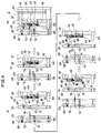
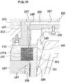
- Fig. 26 to Fig. 38 are enlarged explanatory views of Fig. 26, Fig. 27 and Fig. 30 respectively.
- a plurality of annular horizontal brims 142 which are formed on the outer molding face of the inner core 125 made of the extendible and shrinkable collapsible core in an axially spaced apart manner are snugly fitted into the inner peripheral openings of a plurality of first horizontal annular grooves 135 formed in the inner molding surface of the outer core 134 in an axially spaced apart manner to define spaces for molding the outer peripheral portions of the annular plates 113 of the above-mentioned multi-stacked circular plate fan A.
- molding resin is injected into these outer peripheral portion molding spaces by way of the resin charging passage 155 formed in the injection mold 153, the resin charging passage 154 formed in the stripper 152, the resin inflow space 147, the resin inflow passages 148 defined in the resin inflow guide plate 146 and the first communicating holes 136 for resin inflow (see Fig. 23) formed in the inner molding face of the outer core 134.
- thin blades 135a In this resin injecting operation, thin blades 135a must withstand the injection pressure. If there were no means, the blades 135a are deflected or deformed so that it is difficult to make the width of the all the spaces for molding the outer peripheral portion of the multi-stacked plate fan A uniform.
- the annular horizontal brims 142 are inserted into the first horizontal annular grooves 135, the deformation of the blades 135a can be reliably prevented thus assuring a uniform thickeness of the outer peripheral portion forming space.
- a multi-stacked circular plate fan A as a final product can make all annular circular plates 113 being of a uniform thickness.
- resin can be injected into the circular plate fan molding space by way of a multiplicity of first communicating holes 136 for resin inflow so that the injecting operation can be carried out at a low injection pressure thus enabling the thin mold which can be produced in an inexpensive manner.
- the elevatable carrier 120 is lowered by actuating the elevating device and corresponding to this lowering operation, the fixed mold 145 is removed from the movable mold 128 and the injection mold 153 and the stripper 152 are integrally removed from the fixed mold 145.
- the inner core 125 radially shrinks and this shrinking provides a complete removal of the annular horizontal brims 142 from the first horizontal annular grooves 135.
- a punch is extended downwardly passing through the runner removal punch guide holes 157 formed in the injection mold 153 and the stripper 152 so that the runner 156 can be removed.
- the operating cylinders 124 are actuated to move in a retracting direction while the operating cylinders 162 are actuated to move in an extending direction. Due to such operations, the core mounting frame 123 and the inner core 125 are integrally lowered relative to the elevatable carrier 120 and the center pin 121 which are held stationary.
- the first horizontal annular grooves 135 of the outer core 134 are lowered and expanded on a horizontal plane so that the first horizontal annular grooves 135 are aligned and communicated with the second horizontal annular grooves 140 formed between blades 140a mounted on the outer molding surface of the inner core 125 in an axially spaced apart manner, whereby a space for molding the inner periphery of the annular circular plates 113 of the multi-stacked circular plate fan A is formed.
- the second communicating holes 141 for resin inflow formed in the outer molding surface of the inner core 125 are aligned with the first communicating holes 136 for resin inflow formed in the inner molding surface of the outer core 134.
- the elevating device is actuated to elevate the elevatable carrier 120 and then the movable mold 128, the fixed mold 145, the stripper 152 and the injection mold 153 are integrally assembled again to give rise to a condition which enables a molding operation as in the case of the molding operation shown in Fig. 25. Thereafter, additional molding resin is injected into the inner peripheral molding space by way of the resin charging passage 155 formed in the injection mold 153, the resin charging passage 154 formed in the stripper 152, the resin inflow space 147 and the resin inflow passages 148 formed in the resin inflow guide plate 146 and the second communicating holes 141 for resin inflow (see Fig. 23) formed in the outermolding surface of the inner core 125.
- Molding resin which is injected in this manner forms an inner peripheral portion of each annular plate 113 of the multi-stacked circular plate fan A and is integrally merged with the outer peripheral portion which was already molded to form the annular plates 113.
- molding resin filled in the second communicating holes 141 for resin inflow are integrally merged with spacer portion which was molded in the first communicating holes 136 for resin inflow to mold spacers 114 having a shape of vane.
- the elevatable carrier 120 is lowered again with the actuation of the elevating device.
- the fixed mold 145 is removed from the movable mold 128 and the injection mold 153 and the stripper 152 are integrally removed from the fixed mold 145.
- a punch is extended downwardly passing through the runner removal punch guide holes 157 formed in the injection mold 153 and the stripper 152 so that the runner 156 can be removed.
- the guide operating cylinders 160 is advanced to elevate the core unit protrusion guides 122 along with guide mounting plate 161 relative to the elevatable carrier 120 which is held stationary. Due to this elevating movement, the inclined portions 122a formed at the extremity of the core unit protrusion guides 122 engage with the guide inserting grooves 133 formed in the core units 132 so that the core units 132 retract in a radial direction. Simultaneously, corresponding to the elevating movement of the guide mounting plate 161, the inner core 125 is elevated integrally. Since the center pin 121 is fixed to the elevatable carrier 120 which is stationary, the inner core 125 shrinks radially.
- the fan blade B as a multi-stacked thin plate body can be completely removed outside from the inner core 125 and the outer core 130.
- the elevating device is actuated to elevate the elevatable carrier 120 again.
- the movable mold 128, the fixed mold 145, the stripper 152 and the injection mold 153 are all integrally assembled while the operating cylinders 124 are operated in a retracting direction and the operating cylinders 162 is operated in an advancing direction to establish a moldable condition in Fig. 27.
- This moldable condition is substantially the same as the first step.
- a plurality of annular horizontal brims 142 which are formed on the outer molding face of the inner core 125 made of the extendible and shrinkable collapsible core in an axially spaced apart manner are snugly fitted into the inner peripheral openings of a plurality of first horizontal annular grooves 135 formed in the inner molding surface of the outer core 134 in an axially spaced apart manner to define spaces for molding the outer peripheral portions of the annular plates 113 of the above-mentioned multi-stacked circular plate fan A.
- the multi-stacked circular plates A can be continuously and integrally molded thus enabling the mass production of the precise multi-stacked circular plate fan A in an inexpensive manner.
- the construction of the mold C for molding a multi-stacked circular plate fan is explained in conjunction with Fig. 40 to Fig. 42. Since the multi-stacked circular plate fan A has the same construction as the fan produced by the mold C for molding a multi-stacked circular plate fan according to the second embodiment so that the fan A is explained using the same numerals.
- numeral 220 indicates a carrier which is movable in a frontward or rearward direction by a drive mechanism (not shown in drawings).
- a center pin 221 having a hollow circular cross section which is reciprocably movable so as to expand or shrink an inner core 225 made of the collapsible core is vertically mounted.
- the upper end surface of the center pin 221 functions as a mold for defining an inner surface of a mounting base 113a of the multi-stacked circular plate fan A.
- annular guide mounting frame 223 On the upper surface of the carrier 220, an annular guide mounting frame 223 is concentrically mounted and the proximal end of the cylindrical inner core 225 which works as a mold for forming an inner half portion of the multi-stacked circular plate fan A is fixedly connected to inner periphery of the core mounting frame 223.
- the inner core 225 is provided with, as shown in Fig. 39 to Fig. 40, is provided with a multiplicity of second horizontal grooves 240 defined by a multiplicity of blades 240a on the outer peripheral molding surface. Below the second horizontal annular grooves 240, an annular protruding portion 243 which comes into contact with the upper end of an outer sleeve 238 is provided.
- the blade 240 is provided with a first communicating hole 241 for resin flow which forms a spacer molding portion S1 together with second communication holes 236 for resin flow which will be explained later.
- the inner core 225 comprises a cylindrical body 225b provided with a multiplicity of longitudinal slits 225a having an arcuate cross section in a circumferentially spaced-apart manner, a plurality of elongated members 225c having an arcuate cross section which are fitted into the respective longitudinal slits 225a and the elongated members 225c are fixedly mounted on the cylindrical body 225b by means of a retainer sleeve 225d.
- a thick movable mold 228 having a core through opening 227 is concentrically disposed and the inner core 225 passes through the core through opening 227 in an upward direction.
- the movable mold 228 which forms an outer halve of the multi-stacked circular plate fan A is, as shown in Fig. 42, provided with a plurality of triangular shaped core guide blocks 230 in plan on the upper surface thereof. Between the core guide blocks 230, 230, a core guide groove 231 which extends in a direction toward the center of the movable mold 128 with a desired enlarged inclination ⁇ is formed.
- a core unit 232 is radially and slidably disposed in the core guide groove 231, while the core unit 232 is provided with a guide insert hole 233 through which inclined pins 249 which will pass as will be explained later.
- the above-mentioned plurality of core guide blocks 230 and a plurality of the core units 232 are assembled to form an outer core 234 on the movable mold 228.
- a fixed mold 245 is concentrically disposed.
- Inclined pins 249 which have the lower ends thereof inclined outwardly are fitted into the fixed mold 245. Due to the slide relationship between the slide pins 249 and pin inserting holes 233, corresponding to the elevation movement of the movable mold 228, the core units 232 radially move toward or away from the center of the movable mold 228.
- a contactor mounting base 224 made of a large-sized cylindrical sleeve is mounted on the upper surface of the carrier 220 while on the upper surface of the contactor mounting base 224, an annular contactor 222 which is provided with rectangular grooves 222a on the upper surface is mounted.
- an outer sleeve 238 of a cylindrical shape is slidably disposed and such a sleeve 238 is provided with a tapered inner face 238a squeezed in an upper direction and is provided with brim portions 238b, 238c around the outer periphery at the upper and lower ends thereof.
- the above-mentioned contactor mounting base 224 and the contactor 222 move back and forth integrally with the carrier 220 and the outer sleeve 238 is moved back and forth by the contact of brims 238b, 238c formed at the upper and lower ends thereof with the inner surface of the contactor 222.
- the tapered inner face 238a comes into contact with the above-mentioned annular protruding portion 243 so as to reliably shrink the inner core 225.
- each core unit 232 forms an inner molding surface on the inner surface thereof and a multiplicity of first narrow horizontal grooves 235 are stacked on the inner molding surface in a vertical direction by way of a multiplicity of thin blades 235a. Furthermore, as shown in Fig. 41 and Fig. 42, a second communicating holes 236 for resin inflow which extend in a radial direction are formed in the inner molding surface.
- first communicating holes 241 for resin inflow are formed and these first and second communicating holes 241, 236 for resin inflow are merged to form a spacer molding portions S1.
- a stripper 252 and an injection mold 253 are disposed in layers and a nozzle 254 which communicates with a resin inflow space 247 formed in the upper surface of a resin inflow guide plate 246 is snugly mounted.
- the carrier 220 and the core mounting frame 223 are advanced to assemble the movable mold 228, the fixed mold 245, the stripper 252 and the injection mold 253 integrally.
- the core units 232 of the outer core 234 are shrinked in a direction toward the center due to the slide engagement between the inclined pin 249 and the pin inserting holes 233.
- the inner core 225 is expanded in a radially outward direction by the center pin 221 inserted into the inner core 225 and the inner core 232 is shrinked radially toward the center by the relative slide movement between the inclined pin 249 and the pin inserting hole 233.
- the horizontal grooves 235, 240 formed in the outer core 234 and the inner core 225 respectively are aligned and merged together while the first and the second communicating holes 236, 241 for resin inflow formed in the outer core 234 and the inner core 225 are aligned and merged together whereby the circular plate fan molding space S2 and spacer molding spaces S1 for molding the annular plates 213, spacers 214 and mounting plate 223a can be defined.
- molding resin is injected into these molding spaces by way of the resin charging passage 255 formed in the injection mold 253, the resin charging passage 254 formed in the stripper 252, the resin inflow space 247, the resin inflow passages 248 defined in the resin inflow guide plate 246 and the first and second communicating holes 236, 241 for resin inflow and resin is held in the molding spaces until it is solidified.
- the carrier 220 and the core mounting frame 223 are retracted to disassemble the movable mold 228, the fixed mold 245, the stripper 252 and the injection mold.
- the outer core 234 and the core units 232 are radially outwardly expanded due to the slide engagement between the inclined pins 249 and the pin inserting holes 233, while the inner core 225 is shrinked in a radially inward direction due to the pulling out of the center pin 221 and the contact and slide movement between the tapered inner face 238a of the outer sleeve 238 and the annular protruding portion 243, whereby a molded fan blade B can be removed and taken away outside. Furthermore, a runner which is produced between the stripper 252 and the resin inflow guide plate 246 can be removed (Fig. 43).
- the multi-stacked circular disc plates A can be continuously and integrally molded thus enabling the mass production of the precise multi-stacked circular plate fan A in an inexpensive manner.
- the present invention has following advantages.
Landscapes
- Engineering & Computer Science (AREA)
- Manufacturing & Machinery (AREA)
- Mechanical Engineering (AREA)
- Moulds For Moulding Plastics Or The Like (AREA)
- Structures Of Non-Positive Displacement Pumps (AREA)
Applications Claiming Priority (5)
| Application Number | Priority Date | Filing Date | Title |
|---|---|---|---|
| JP266378/92 | 1992-10-05 | ||
| JP26637892 | 1992-10-05 | ||
| JP159500/93 | 1993-06-29 | ||
| JP15950093 | 1993-06-29 | ||
| PCT/JP1993/001422 WO1994007676A1 (fr) | 1992-10-05 | 1993-10-04 | Filiere de moulage pour soufflante a disques multi-couches et procede de fabrication de soufflante a disques multi-couches l'utilisant |
Publications (2)
| Publication Number | Publication Date |
|---|---|
| EP0627293A1 true EP0627293A1 (de) | 1994-12-07 |
| EP0627293A4 EP0627293A4 (de) | 1995-04-05 |
Family
ID=26486283
Family Applications (1)
| Application Number | Title | Priority Date | Filing Date |
|---|---|---|---|
| EP93921110A Withdrawn EP0627293A4 (de) | 1992-10-05 | 1993-10-04 | Formdüse zum Blasen von mehrschichtigen Platten und Verfahren zum Blasen von mehrschichtigen Platten unter Verwendung dieser Düse. |
Country Status (2)
| Country | Link |
|---|---|
| EP (1) | EP0627293A4 (de) |
| WO (1) | WO1994007676A1 (de) |
Cited By (3)
| Publication number | Priority date | Publication date | Assignee | Title |
|---|---|---|---|---|
| WO2008054319A3 (en) * | 2006-11-01 | 2008-06-19 | Hans Mueller | Device at collapsible core, preferably at injection moulding tool for plastic material, silicone, rubber and similar material |
| US9945389B2 (en) | 2014-05-05 | 2018-04-17 | Horton, Inc. | Composite fan |
| CN110587923A (zh) * | 2019-09-16 | 2019-12-20 | 珠海集致科技有限公司 | 一种电吹风外壳注塑模具及其注塑成型方法 |
Family Cites Families (3)
| Publication number | Priority date | Publication date | Assignee | Title |
|---|---|---|---|---|
| GB1050173A (de) * | 1900-01-01 | |||
| FR2061839A5 (de) * | 1969-05-29 | 1971-06-25 | Crouzet & Cie | |
| JPH02212112A (ja) * | 1989-02-13 | 1990-08-23 | Aisan Ind Co Ltd | 樹脂成形用金型 |
-
1993
- 1993-10-04 EP EP93921110A patent/EP0627293A4/de not_active Withdrawn
- 1993-10-04 WO PCT/JP1993/001422 patent/WO1994007676A1/ja not_active Ceased
Cited By (6)
| Publication number | Priority date | Publication date | Assignee | Title |
|---|---|---|---|---|
| WO2008054319A3 (en) * | 2006-11-01 | 2008-06-19 | Hans Mueller | Device at collapsible core, preferably at injection moulding tool for plastic material, silicone, rubber and similar material |
| US9945389B2 (en) | 2014-05-05 | 2018-04-17 | Horton, Inc. | Composite fan |
| US10415587B2 (en) | 2014-05-05 | 2019-09-17 | Horton, Inc. | Composite fan and method of manufacture |
| US10914314B2 (en) | 2014-05-05 | 2021-02-09 | Horton, Inc. | Modular fan assembly |
| CN110587923A (zh) * | 2019-09-16 | 2019-12-20 | 珠海集致科技有限公司 | 一种电吹风外壳注塑模具及其注塑成型方法 |
| CN110587923B (zh) * | 2019-09-16 | 2021-01-05 | 珠海集致科技有限公司 | 一种电吹风外壳注塑模具及其注塑成型方法 |
Also Published As
| Publication number | Publication date |
|---|---|
| EP0627293A4 (de) | 1995-04-05 |
| WO1994007676A1 (fr) | 1994-04-14 |
Similar Documents
| Publication | Publication Date | Title |
|---|---|---|
| US4249882A (en) | Die casting system for the production of rubber mouldings | |
| CN105459345B (zh) | 一种换气扇扇叶注塑模具 | |
| KR100460587B1 (ko) | 터보팬 및 그 제조용 금형 | |
| EP0627293A1 (de) | Formdüse für scheibenlüfter und verfahren zur herstellung von scheibenlüftern unter verwendung dieser düse | |
| US3978186A (en) | Method for making a partitioned container | |
| US3977821A (en) | Apparatus for making a partitioned container | |
| CN115194028A (zh) | 一种可微调不同尺寸模具冲头的冲压模具 | |
| CN220261771U (zh) | 一种管盖一体成型注塑模具装置 | |
| CN218519086U (zh) | 圆形外壳注塑模具 | |
| JP3385556B2 (ja) | 送風機用多翼車の射出成形方法および射出成形金型 | |
| CN209999631U (zh) | 洗衣机法兰成型模具 | |
| CN222590552U (zh) | 一种高效注塑模具 | |
| CN1461697A (zh) | 侧浇口自动切断注射模 | |
| CN222077923U (zh) | 一种铝合金轮毂用模具 | |
| JPWO1994007676A1 (ja) | 多層円板ファン成形用金型及び同金型を用いた多層円板ファンの製造方法 | |
| CN113414945A (zh) | 一种电源插头自动注塑生产线 | |
| CN224089540U (zh) | 一种汽车电驱动滤波支架的注塑模具 | |
| CN222858626U (zh) | 一种用于批量生产的注塑模具 | |
| CN219855698U (zh) | 一种拆卸式注塑模具 | |
| CN215242511U (zh) | 一种汽车扒胎机支脚的注塑模具 | |
| CN219133061U (zh) | 二次包胶模具 | |
| JP3263972B2 (ja) | 薄肉板多層積層体の成形方法及び装置 | |
| CN219988354U (zh) | 具有复合顶出机构的高承载田字塑料托盘成型模具 | |
| CN221496901U (zh) | 密封件高效成型模具 | |
| CN213055797U (zh) | 静脉针针柄模具 |
Legal Events
| Date | Code | Title | Description |
|---|---|---|---|
| PUAI | Public reference made under article 153(3) epc to a published international application that has entered the european phase |
Free format text: ORIGINAL CODE: 0009012 |
|
| 17P | Request for examination filed |
Effective date: 19940607 |
|
| AK | Designated contracting states |
Kind code of ref document: A1 Designated state(s): AT BE CH DE DK ES FR GB GR IE IT LI LU MC NL PT SE |
|
| A4 | Supplementary search report drawn up and despatched | ||
| AK | Designated contracting states |
Kind code of ref document: A4 Designated state(s): AT BE CH DE DK ES FR GB GR IE IT LI LU MC NL PT SE |
|
| 17Q | First examination report despatched |
Effective date: 19951227 |
|
| STAA | Information on the status of an ep patent application or granted ep patent |
Free format text: STATUS: THE APPLICATION IS DEEMED TO BE WITHDRAWN |
|
| 18D | Application deemed to be withdrawn |
Effective date: 19960507 |