EP0623977A1 - Kabelanordnung für mehrere elektronische Komponenten - Google Patents
Kabelanordnung für mehrere elektronische Komponenten Download PDFInfo
- Publication number
- EP0623977A1 EP0623977A1 EP94105887A EP94105887A EP0623977A1 EP 0623977 A1 EP0623977 A1 EP 0623977A1 EP 94105887 A EP94105887 A EP 94105887A EP 94105887 A EP94105887 A EP 94105887A EP 0623977 A1 EP0623977 A1 EP 0623977A1
- Authority
- EP
- European Patent Office
- Prior art keywords
- input
- module
- coupling
- flexible cable
- circuit board
- Prior art date
- Legal status (The legal status is an assumption and is not a legal conclusion. Google has not performed a legal analysis and makes no representation as to the accuracy of the status listed.)
- Withdrawn
Links
Images


Classifications
-
- H—ELECTRICITY
- H01—ELECTRIC ELEMENTS
- H01R—ELECTRICALLY-CONDUCTIVE CONNECTIONS; STRUCTURAL ASSOCIATIONS OF A PLURALITY OF MUTUALLY-INSULATED ELECTRICAL CONNECTING ELEMENTS; COUPLING DEVICES; CURRENT COLLECTORS
- H01R25/00—Coupling parts adapted for simultaneous co-operation with two or more identical counterparts, e.g. for distributing energy to two or more circuits
- H01R25/16—Rails or bus-bars provided with a plurality of discrete connecting locations for counterparts
- H01R25/161—Details
-
- H—ELECTRICITY
- H02—GENERATION; CONVERSION OR DISTRIBUTION OF ELECTRIC POWER
- H02G—INSTALLATION OF ELECTRIC CABLES OR LINES, OR OF COMBINED OPTICAL AND ELECTRIC CABLES OR LINES
- H02G3/00—Installations of electric cables or lines or protective tubing therefor in or on buildings, equivalent structures or vehicles
-
- H—ELECTRICITY
- H01—ELECTRIC ELEMENTS
- H01H—ELECTRIC SWITCHES; RELAYS; SELECTORS; EMERGENCY PROTECTIVE DEVICES
- H01H2300/00—Orthogonal indexing scheme relating to electric switches, relays, selectors or emergency protective devices covered by H01H
- H01H2300/03—Application domotique, e.g. for house automation, bus connected switches, sensors, loads or intelligent wiring
-
- H—ELECTRICITY
- H01—ELECTRIC ELEMENTS
- H01R—ELECTRICALLY-CONDUCTIVE CONNECTIONS; STRUCTURAL ASSOCIATIONS OF A PLURALITY OF MUTUALLY-INSULATED ELECTRICAL CONNECTING ELEMENTS; COUPLING DEVICES; CURRENT COLLECTORS
- H01R12/00—Structural associations of a plurality of mutually-insulated electrical connecting elements, specially adapted for printed circuits, e.g. printed circuit boards [PCB], flat or ribbon cables, or like generally planar structures, e.g. terminal strips, terminal blocks; Coupling devices specially adapted for printed circuits, flat or ribbon cables, or like generally planar structures; Terminals specially adapted for contact with, or insertion into, printed circuits, flat or ribbon cables, or like generally planar structures
- H01R12/50—Fixed connections
- H01R12/59—Fixed connections for flexible printed circuits, flat or ribbon cables or like structures
-
- H—ELECTRICITY
- H01—ELECTRIC ELEMENTS
- H01R—ELECTRICALLY-CONDUCTIVE CONNECTIONS; STRUCTURAL ASSOCIATIONS OF A PLURALITY OF MUTUALLY-INSULATED ELECTRICAL CONNECTING ELEMENTS; COUPLING DEVICES; CURRENT COLLECTORS
- H01R31/00—Coupling parts supported only by co-operation with counterpart
- H01R31/02—Intermediate parts for distributing energy to two or more circuits in parallel, e.g. splitter
-
- Y—GENERAL TAGGING OF NEW TECHNOLOGICAL DEVELOPMENTS; GENERAL TAGGING OF CROSS-SECTIONAL TECHNOLOGIES SPANNING OVER SEVERAL SECTIONS OF THE IPC; TECHNICAL SUBJECTS COVERED BY FORMER USPC CROSS-REFERENCE ART COLLECTIONS [XRACs] AND DIGESTS
- Y02—TECHNOLOGIES OR APPLICATIONS FOR MITIGATION OR ADAPTATION AGAINST CLIMATE CHANGE
- Y02B—CLIMATE CHANGE MITIGATION TECHNOLOGIES RELATED TO BUILDINGS, e.g. HOUSING, HOUSE APPLIANCES OR RELATED END-USER APPLICATIONS
- Y02B90/00—Enabling technologies or technologies with a potential or indirect contribution to GHG emissions mitigation
- Y02B90/20—Smart grids as enabling technology in buildings sector
-
- Y—GENERAL TAGGING OF NEW TECHNOLOGICAL DEVELOPMENTS; GENERAL TAGGING OF CROSS-SECTIONAL TECHNOLOGIES SPANNING OVER SEVERAL SECTIONS OF THE IPC; TECHNICAL SUBJECTS COVERED BY FORMER USPC CROSS-REFERENCE ART COLLECTIONS [XRACs] AND DIGESTS
- Y04—INFORMATION OR COMMUNICATION TECHNOLOGIES HAVING AN IMPACT ON OTHER TECHNOLOGY AREAS
- Y04S—SYSTEMS INTEGRATING TECHNOLOGIES RELATED TO POWER NETWORK OPERATION, COMMUNICATION OR INFORMATION TECHNOLOGIES FOR IMPROVING THE ELECTRICAL POWER GENERATION, TRANSMISSION, DISTRIBUTION, MANAGEMENT OR USAGE, i.e. SMART GRIDS
- Y04S20/00—Management or operation of end-user stationary applications or the last stages of power distribution; Controlling, monitoring or operating thereof
- Y04S20/14—Protecting elements, switches, relays or circuit breakers
Definitions
- the invention relates to cabling assemblies for electrically coupling various electronic components, e.g., televisions (TV's), video cassette recorders (VCR's), amplifiers, etc., to a suitable power source, e.g., AC.
- TV's televisions
- VCR's video cassette recorders
- AC AC power source
- Patent 4,602,164 (Gore et al), there is described a system for packaging and grounding various electronic devices such as personal computers, the system primarily designed to provide EMI shielding and requiring use of an electrical interface coupled to the various devices using individual wiring or the like.
- This system provides such protection through use of an electrically conductive housing containing the interfacing, main processing unit (MPU), but, as indicated, appears to require separate wiring to couple the MPU to the individual external devices.
- MPU main processing unit
- the present invention provides a new and unique means for electrically coupling a plurality of electronic components as defined above without the necessity of a multitude of electrical wires, antenna and cable leads, etc. which would otherwise present an unsightly appearance and also present a potential safety problem, e.g., from tripping, to the system's user.
- the invention as defined herein is relatively inexpensive, easy to operate, and, equally significant, adaptable to many existing entertainment systems including the aforementioned and similar components.
- the invention combines the advantageous teachings of using flexible cabling in addition to connection structures of relatively simple design for providing needed coupling.
- the invention does not require close positioning of the various components being coupled, e.g., on a common frame or the like, does not require relatively complicated and costly interconnecting structures and functional elements, nor does the invention mandate individual connections, e.g., wiring, between a common control unit (if utilized) and each of the various peripheral components which operate in conjunction therewith.
- the cable assembly as defined herein is readily adaptable to other than entertainment systems and may in fact be used in more commercial settings, including a typical business office setting wherein electronic components such as computers, printers, and facsimile machines are employed.
- a cable assembly for electrically coupling a plurality of electronic components to a common power source, e.g., AC, wherein the assembly includes an input module for being coupled to the power source, at least one junction module for being coupled to the input module, at least one adapter associated with each of the respective electronic components being coupled by the invention, a first flexible cable member for electrically coupling the input and junction modules, and at least one second flexible cable member for electrically coupling the junction module with a respective adapter.
- a first flexible cable member for electrically coupling the input and junction modules
- at least one second flexible cable member for electrically coupling the junction module with a respective adapter.
- more than one such second flexible cable members will be utilized, depending on the number of adapters (and thus electronic components) used in the overall system.
- a method for coupling electronic components to a common power source comprising the steps of directly coupling an input module to a common power source, coupling at least one junction module to the input module using a singular, first flexible cable member, directly coupling an adapter to a respective one of each of the electronic components, and coupling the junction module to each of the adapters using a singular, second flexible cable member, thereby coupling the electronic components to the common power source.
- input module will mean an electrical structure for electrically coupling, e.g., directly, to a power source such as AC to receive electrical current therefrom and also capable of receiving other input means such as TV cable connections, antenna connections, etc. in order to pass the current from such a source and the signals from such input means on to other parts of the invention.
- junction module as used herein will mean an electrical structure for electrically coupling the input module to other parts of the invention, particularly the adapter(s) for use herein, to pass electrical current and the aforementioned signals to said other parts as needed.
- flexible cable as used herein will mean an electrically insulative member having a plurality of conductor elements, e.g., wiring, therein to provide an appropriate passage for the various signals and current between the various module and adapter elements of the invention, as required to effectively operate the system, e.g., home entertainment, coupled by the invention.
- circuit board as used herein will mean a dielectric substrate having a plurality of electrical conductor traces or lines therein and/or thereon.
- Several various circuit board structures are known in the art, as are the several different dielectric materials, e.g., fiberglass reinforced epoxy resin, Teflon (a trademark of the E. I. duPont de Nemours Company), etc.
- electronic component as used herein will mean any electrical device or unit capable of performing an electrical function, primary examples of such components being, as also stated hereinabove, TV's, VCR's, phonographs, AM/FM tuners and amplifiers, speakers, compact disk (CD) players, personal computers (PC's), video cameras, etc.
- Other examples e.g., if an office setting, may include photocopiers, printers, facsimile machines, etc.
- FIG. 1 there is shown a cable assembly 10 in accordance with a preferred embodiment of the invention.
- Assembly 10 is designed for electrically coupling a plurality of electronic components, e.g., a TV 11 and a AM/FM tuner/amplifier 13, to a suitable power source, e.g., AC.
- a suitable power source e.g., AC.
- FIG. 1 Although only two such components are illustrated in FIG. 1, it is well understood that the invention is capable of coupling several more such components. The two shown are thus provided for illustration purposes only.
- Cable assembly 10 is uniquely adaptable for ready utilization with many existing components currently on the market without substantial modification thereto. As will be described hereinbelow, substantially all currently known such components can be readily attached to (and thus coupled by) the present invention with minimal effort. Further, the invention is readily usable by the average consumer.
- cable assembly 10 includes an input module 15 which, as defined in greater detail hereinbelow, is capable of being directly coupled to the preferred, common power source.
- input module 15 includes a conductive wire 17 (see also FIG. 2) which can be directly inserted within a typical socket found in the homes of many consumers.
- Cable assembly 10 further includes at least one junction module 19 which, as defined, is electrically coupled to input module 15 and serves as a junction for eventual coupling to the various electronic components of the system, e.g., home entertainment, being coupled.
- junction module 19 includes at least four coupling locations, one designated for the respective coupling means to input module 15, with the remainder designated for coupling to other parts of the invention as desired.
- Cable assembly 10, as further shown in FIG. 1, further includes at least one adapter 21 (see also FIG. 5) for being directly electrically coupled to a respective one of the system's electronic components. Accordingly, a singular adapter is used for each such component, to couple said component to cable assembly 10 and thus to the common power source.
- two junction modules 19 are illustrated in FIG. 1, it is understood that only one such module is necessary for the particular embodiment depicted in FIG. 1. This is possible because the first module (the lower) includes three designated coupling locations to thus serve the three adapters depicted in FIG. 1 (the third adapter being to the left) utilized in conjunction with an optional control unit 23, described below.
- the second junction module (the upper) in FIG. 1 is thus provided for illustration purposes only to further represent the additional capabilities of the present invention.
- Cable assembly 10 further includes a first flexible cable member 25 for electrically coupling the input module 15 and first junction module 19.
- first flexible cable member 25 for electrically coupling the input module 15 and first junction module 19.
- cable assembly 10 in FIG. 1 further includes a second flexible cable member 27 for electrically coupling the invention's junction modules 19 to the described adapters 21.
- a second flexible cable member will also be described in greater detail hereinbelow.
- the invention provides a new and unique cable assembly for electrically coupling a plurality of various electronic components to a singular power source using a minimum of flexible electrical cabling.
- the invention provides means for transmitting both electrical current and various electronic signals through this common cabling system using the minimum elements described above and hereinbelow.
- the invention thus overcomes the need for massive electrical wiring between each of several such electronic components and the designated power source.
- the invention in addition to being of relatively uncomplex structure, is capable of being operated (e.g., segmented as needed) in a facile manner by the average consumer.
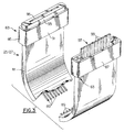
- Input module 15 preferably includes a two-part housing 31 having therein at least one circuit board 33.
- Housing 31 is preferably a molded polymer (plastic) material which, when fastened, substantially covers the central body portion 35 of board 33 to enable projecting edge portions 37 thereof to project externally through associated slots 39 formed in the housing.
- the projecting edge portions 37 may project a total distance of about 0.500 inch from the respective outer surfaces of the rectangular-shaped housing.
- input module 15 includes additional electrical elements which are electrically coupled to associated circuitry, e.g., 41, located on the dielectric (fiberglass-reinforced epoxy resin) substrate 43 of board 33.
- the circuitry 41 is preferably plated copper or the like provided on and/or within the dielectric substrate in accordance with known technology.
- the board 33 shown in FIG. 2 may include a circuit breaker reset device 51, an associated on/off indicator 53, a computer input (phone jack) 55, various AC regulators 57, e.g., a line filter and surge suppressor, a cable (TV) input 59, etc.
- board 33 includes a plurality of input/output conductors 61 located along each of the three illustrated projecting edges 37. Eight such conductors are illustrated for each projecting edge, but it is understood that the invention is not limited to this number as the appropriate number to be utilized depends on the particular system requirements.
- Each such conductor for each respective edge includes a corresponding, similar conductor at a similar location along each of the respective, other conductor edges on board 33, excluding the lower edge.
- board 33 also includes input/output conductors (63) for being electrically coupled, e.g., soldered, to the conductive leads of connecting wire 17, which wire, as mentioned, is capable of being directly plugged into a home socket or other electrical structure associated with typical line current (AC).
- input/output conductors (63) for being electrically coupled, e.g., soldered, to the conductive leads of connecting wire 17, which wire, as mentioned, is capable of being directly plugged into a home socket or other electrical structure associated with typical line current (AC).
- AC line current
- input module 15 is of the rectangular shape configuration as shown with side dimensions each of a total length of about three inches.
- the overall thickness for such a structure is preferably only about one inch. This part of the invention thus presents a compact design of relatively small overall size.
- the illustrated pattern of conductors 61 for each of the three edge patterns are preferably identical and include similar functions, e.g., AC power (common), audio signal, video signal, antenna (common), etc., in a similar predefined order for each edge portion.
- Such duplication reduces the complexity of the design and facilitates coupling to similar structures, e.g., cable member 25.
- each of the respective conductors are of a predetermined width and thickness depending on the desired function for these. These conductors may include similar dimensions to those identified below for conductors (89, FIG. 3) in the invention's flexible cable members.
- first flexible cable member 25 for use with the invention.
- flexible cable member 25 includes a flexible segment 81 having opposed ends 83 with couplers 85 and 87 thereon.
- each flexible cable segment 81 is comprised of a substantially flat dielectric material (e.g., polyamide) having therein the desired number of conductors 89 for transmitting electrical current and designated signals through the flexible cable between the respective locations being coupled.
- copper wiring is used for each conductor path 89, this wiring differing in thickness depending on the operational requirement therefor. For example, the thickness of the wiring used to conduct electrical current may be thicker than that required to transmit audio and/or video signals.
- the designated conductor wire for carrying electrical current may possess a thickness similar to that of 14 or 16 gauge wiring, while the designated wiring for audio and/or video signals may possess a thickness similar to that of 20 or 22 gauge wiring.
- eight such conductors are illustrated in FIG. 3, the invention is obviously not limited thereto as this number may increase or decrease depending on the desired operational capabilities for the invention.
- Coupler 85 and 87 are represented in both the female and male versions thereof.
- Coupler 85 is, as shown, of the female type and includes a molded, conductive polymer (plastic) member 91 sealed onto the end of the flexible cable segment and further including a female portion 93 as part thereof.
- Member 91 is electrically conductive to assure electromagnetic compatibility with internal elements (e.g., conductors 89).
- Portion 93 includes a slot 95 therein for receiving a respective projecting edge portion of circuit board 33 of input module 15.
- Each of the illustrated conductor wiring 89 includes a terminal end (not shown) which extends within slot 93, e.g., as a conductor trace or the like, such that when the respective conductors 61 on edge portions 37 are inserted within slot 95, said conductors will engage these terminating end portions, preferably in a frictional manner, to thus provide effective contact therewith. Accordingly, the respective widths of the terminal ends of conductor wiring 89 and the associated conductors 61 on each respective projecting edge portion 37 are substantially the same.
- Coupler 87 of the male variety, includes a projecting edge segment 97 having a plurality of conductor traces 99 thereon, each of which is electrically connected to or forms an extension of a respective conductor wire 89.
- This male coupler 87 is thus ideally suited for being connected to an associated module, either input or junction, should such module be of a female configuration.
- Such a configuration is readily possible, e.g., for the input module in FIG. 2, by providing a circuit board with internally located edge portions (and thus not projecting as shown) such that the extending edge 97 may be inserted within the respective, provided opening or slot 39 to frictionally engage the edge portion and effect connection between the spaced conductors 61 and 99.
- Such spacings are thus substantially similar for this purpose.
- the adapters 21 defined hereinbelow are ideally suited for coupling to a respective male coupler 87.
- the particular flexible cable member 25 illustrated in FIG. 3 is thus capable of being used for both the first and second flexible cable members of assembly 10. It is also possible, as understood, to utilize such a member with both female couplers or male couplers thereon, rather than the alternative versions illustrated.
- the desired flexible cable member to be used for first cable 25 includes both female couplers 83 as part thereof.
- the particular embodiment depicted in FIG. 3 is utilized for the second flexible cable member 27. Again, however, this particular embodiment can be used for both cable members of the invention depending on the corresponding designs for the respective adapters and modules being coupled.
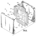
- Module 19 in accordance with a preferred embodiment of the invention.
- Module 19 like input module 15, includes a two-part housing 31' having channels for openings 39' therein similar to those in FIG. 2. Such a housing is preferably of the same material as housing 31.
- Module 19 further includes a common circuit board 101 with, preferably, four similar projecting edge portions 103.
- Each edge portion 103 includes a plurality of conductors 105 which, like those (61) in FIG. 2, run to the edge and are electrically interconnected through appropriate circuit traces, e.g., 104.
- These traces similar to those conductor lines 41, are located upon and/or within the dielectric, e.g., fiberglass reinforced epoxy resin, of circuit board 101.
- dielectric e.g., fiberglass reinforced epoxy resin
- each pattern of conductors (105) is similar to the other patterns for the advantages cited above. Additionally, each respective conductor is electrically coupled to the corresponding, similar conductor in the remaining patterns.
- a housing having side dimensions of about three inches and an overall thickness of about one inch is preferred, with the projecting hedge portions 103 extending a distance of about 0.500 inch from the peripheral outer surfaces of the closed housing.
- circuit conductors 105 may involve shortening of each edge portion such that these will be recessed within housing 31' to accommodate receipt of a respective projecting edge 97 of such a coupler.
- circuit conductors 105 are shown in FIG. 4, the invention is, of course, not limited thereto in that any number of such conductors may be provided, depending on the operational requirements for the invention. Such conductors may also possess different widths and thicknesses depending on the required function for each.
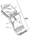
- FIG. 5 there is shown one embodiment of an adaptor 21 for use in the present invention.
- an adaptor is utilized for being electrically coupled to a respective electronic component.
- Adaptor 21 preferably includes an enclosing housing 111 (only partially shown in FIG. 5, the cover shown in phantom) of electrically conductive (e.g., conductive polymer) material, having therein a printed circuit board 113 which, as illustrated, includes a plurality of conductive traces 115 thereon. Traces 115, being mounted on an insulative board, are of course electrically isolated from the conductive housing.
- electrically conductive e.g., conductive polymer
- Board 113 is of a known dielectric as cited above and traces 115 are also of known material, e.g., copper. Conductive traces 115 terminate at the edge of board 113, e.g., at female (apertured) pads 121. To these termination pads 121 may be electrically coupled the various conductive means which are necessary for use with the respective electronic component.
- the various coupling means from adaptor 21 may include an audio input lead 123, a video input lead 125, a video output lead 127 and an electrical ground 129.
- adaptor 21 may include an input section 131 for coupling the electrical wire 133 from such a component thereto, to thus couple the component to an associated power source, e.g., AC.
- Other leads or the like may also be provided and coupled, preferably in a separable fashion as shown in FIG. 5 for conductor 129, with respect to adaptor 21.
- Conductive traces 115 terminate at the opposite end (from pads 121) in a protruding female section 141 which is substantially similar to section 93 for coupler 85 in FIG. 3. Accordingly, section 141 includes a slot 143 therein for receiving a respective projecting male portion 97 (FIG. 6) of an end portion of the desired flexible cable member (25 or 27) for coupling thereto.
- Housing 111 is electrically conductive for the same reasons stated above with respect to member 91. Traces 115, located on a dielectric board, are of course isolated from housing 111.
- FIG. 5 also illustrates one example of a separable connection device for connecting the respective ends of such leads 123, 125, 127 and 129 to the corresponding edge of adapter 21.
- the termination of each lead may include a ground lead and a "hot" lead, both housed in a crimp-type connector 147 and an associated receptacle 143, secured to connector 147, e.g., with screw threads.
- Receptacle 143 includes projecting pins 145 which in turn may be soldered within respective openings 146 in the terminating pads 121.
- control unit 23 (FIG. 1) which in turn may provide the function of controlling the mode of operation of various ones of the electronic components being coupled by assembly 10.
- a control unit may be remotely operated by a suitable remote control (not shown), voice activation or the like.
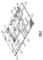
- FIG. 7 there is shown one example of a circuit board structure 151 which may form part of unit 23.
- a protective housing 153 having a plurality of sides and respective bottom and top covers.
- Such a housing would preferably be of electrically conductive material, e.g., conductive polymer (to provide electromagnetic compatibility). Effective connections thereto would be provided by associated leads, wiring or the like such as illustrated in FIG. 5.
- Board structure 151 may include a plurality of electrical components as shown. Each of these components is preferably coupled using conductive traces 155 located on and/or within the boards' dielectric. Known dielectrics and trace materials, such as cited above, may be used. Preferably, each trace terminates with an edge pad 157 similarly to the boards in FIG. 2, 4 and 5.
- board 151 may include the following electrical components: (1) a central processing unit (CPU) 161, including a memory semiconductor device (chip); (2) an LED display 163 (preferably aligned with a respective opening (not shown) in one of the sides of housing 153); (3) a selector bar 165; (4) a programmable sensor pad 164 for remote control and/or voice activation reception; (5) a power-on indicator 169; (6) an enabling switch 171 that activates the function chosen, by the selector bar, via coupling the corresponding circuits and transmitting the signals to the selected electronic components; and (7) a plurality of discreet components 173, such as capacitors, resistors, inductors, etc., as needed.
- CPU central processing unit
- LED display 163 preferably aligned with a respective opening (not shown) in one of the sides of housing 153
- a selector bar 165 preferably aligned with a respective opening (not shown) in one of the sides of housing 153
- a selector bar 165 preferably aligne
- board 151 may also include micro-switching elements 175 for linking circuits via the selector bar.
- the number 177 in FIG. 7 represents a preferred location for an audio output, if desired, while numeral 179 represents a preferred location for an audio input to board 151.
- CPU 161 will function to process all indicator, selector, voice activation, etc., signals and to disseminate these to the respective junctions.
- Appropriate connections to the respective terminal edge conductors 157 with the respective wiring, which is represented by number 181 in FIG. 1, may be accomplished by known techniques, e.g., soldering, or the like or, as identified in FIG. 5, be of the separable type to enable ready separation thereof, if desired. It is possible to utilize separable leads and/or conductive wiring to couple to the adaptor 21 as shown in FIG. 5, with fixed attachments between the respective opposing ends of these elements and the associated conductors on the circuit board 151 used in control unit 23.
- the invention thus defines a means whereby a plurality of electronic components may be effectively coupled to a common power source or the like using a minimum number of elements. Additionally, the invention as defined is of relatively simple construction and thus relatively easy to operate for the average consumer. Further, the invention presents an affordable alternative to the existing practice of requiring several wires and/or leads to individually couple each such component. Although the invention as defined herein has identified such coupling to be of electrical nature, it is also within the scope of the invention to provide suitable fiber optic coupling at designated portions thereof (e.g., to replace selected ones of the aforementioned copper wires 89 (FIG. 3) with optical fibers having appropriate terminal ends (e.g., retaining ferrules) as are known in the art).
- suitable fiber optic coupling at designated portions thereof (e.g., to replace selected ones of the aforementioned copper wires 89 (FIG. 3) with optical fibers having appropriate terminal ends (e.g., retaining ferrules) as are known in the art).
Applications Claiming Priority (2)
| Application Number | Priority Date | Filing Date | Title |
|---|---|---|---|
| US5736393A | 1993-05-05 | 1993-05-05 | |
| US57363 | 1993-05-05 |
Publications (1)
| Publication Number | Publication Date |
|---|---|
| EP0623977A1 true EP0623977A1 (de) | 1994-11-09 |
Family
ID=22010114
Family Applications (1)
| Application Number | Title | Priority Date | Filing Date |
|---|---|---|---|
| EP94105887A Withdrawn EP0623977A1 (de) | 1993-05-05 | 1994-04-15 | Kabelanordnung für mehrere elektronische Komponenten |
Country Status (3)
| Country | Link |
|---|---|
| US (1) | US5507668A (de) |
| EP (1) | EP0623977A1 (de) |
| JP (1) | JP3006398B2 (de) |
Cited By (4)
| Publication number | Priority date | Publication date | Assignee | Title |
|---|---|---|---|---|
| DE19923893A1 (de) * | 1999-05-25 | 2000-11-30 | Bayerische Motoren Werke Ag | Elektrisches Verdrahtungssystem für die Antriebseinheit in Fahrzeugen |
| DE10017484A1 (de) * | 2000-04-07 | 2001-10-18 | Ralf Wieduwilt | Niederspannungs-Verteilungssystem |
| DE10149889A1 (de) * | 2001-10-10 | 2003-05-08 | Ralf Wieduwilt | Niederspannungs-Verteilungssystem |
| EP1777790A1 (de) * | 2005-10-24 | 2007-04-25 | Wexio AB | Sicheres Verteilungssystem zur Verzorgung von elektrischer Energie oder Signalen |
Families Citing this family (54)
| Publication number | Priority date | Publication date | Assignee | Title |
|---|---|---|---|---|
| US5679023A (en) * | 1995-08-23 | 1997-10-21 | Nsi Enterprises, Inc. | Female cable connector head for relocatable wiring systems and methods for manufacture thereof |
| US5766027A (en) * | 1995-12-21 | 1998-06-16 | The Whitaker Corporation | Cable assembly with equalizer board |
| US5971799A (en) * | 1997-04-26 | 1999-10-26 | Swade; George | Y-shaped harness for the interconnection between a vehicle radio, a vehicle harness and add-on electronic device |
| US5855494A (en) * | 1997-05-05 | 1999-01-05 | 3 Com Corp. | Apparatus and method for electrically connecting a plurality of electronic modules |
| USD405049S (en) * | 1997-05-07 | 1999-02-02 | Aitech Int'l Corporation | X-cable between a TV and a computer |
| TW343004U (en) * | 1997-08-09 | 1998-10-11 | Hon Hai Prec Ind Co Ltd | Electric power transferring apparatus |
| US6511327B1 (en) * | 1997-09-29 | 2003-01-28 | Avaya Technology Corp. | Simplified network interface device |
| US6179627B1 (en) * | 1998-04-22 | 2001-01-30 | Stratos Lightwave, Inc. | High speed interface converter module |
| US6430526B1 (en) * | 1998-12-22 | 2002-08-06 | Intel Corporation | Computer processable interconnect topology |
| JP2001035616A (ja) | 1999-07-21 | 2001-02-09 | Sumitomo Wiring Syst Ltd | ワイヤハーネス用ジョイントコネクタ |
| WO2001015285A1 (en) * | 1999-08-23 | 2001-03-01 | Mass Engineered Design | Universal quick connector apparatus for an lcd monitor |
| US6487091B2 (en) * | 1999-09-28 | 2002-11-26 | Rockwell Automation Technologies, Inc. | Method and apparatus for supplying data and power to panel-supported components |
| US6241534B1 (en) * | 2000-01-25 | 2001-06-05 | Molex Incorporated | GBIC connector with circuit board mating faces |
| US6314001B1 (en) * | 2000-06-28 | 2001-11-06 | Meridian Technology Corp. | Desktop computer with external power supply module |
| GB0018426D0 (en) * | 2000-07-28 | 2000-09-13 | Pace Micro Tech Plc | Scart to phono converter |
| JP2002160591A (ja) * | 2000-11-27 | 2002-06-04 | Yazaki Corp | 車両用配線回路体 |
| US7969702B2 (en) * | 2000-12-06 | 2011-06-28 | Motorola Mobility, Inc. | Intelligent power supply and cable system |
| JP2002315154A (ja) * | 2001-04-12 | 2002-10-25 | Sumitomo Wiring Syst Ltd | ジャンクションボックスとワイヤハーネスの接続方法 |
| US20030176109A1 (en) * | 2002-03-05 | 2003-09-18 | Hiroaki Fukuchi | Connecting member |
| US20040018778A1 (en) * | 2002-07-23 | 2004-01-29 | Walter Easterbrook | Systems and methods for connecting components in an entertainment system |
| KR20040035541A (ko) * | 2002-10-22 | 2004-04-29 | 이재선 | 밴드형 접착식 유선연결장치 |
| TW573846U (en) * | 2003-04-11 | 2004-01-21 | Quick Serv Comp Co Ltd | Signal transmission cable |
| US6881093B2 (en) * | 2003-08-04 | 2005-04-19 | German Antonio Carmona | Wiring module for automotive vehicle |
| US7018232B2 (en) * | 2003-08-04 | 2006-03-28 | German Antonio Carmona | Wiring module for automotive vehicle |
| US7560828B2 (en) * | 2003-10-24 | 2009-07-14 | William Fondriest | Modular electrical harness for military vehicles adapted with the multiple integrated laser engagement system |
| CA2594801A1 (en) * | 2004-01-12 | 2005-07-21 | Jerry Moscovitch | Apparatus and method for adding a monitor to a display system |
| US7488202B2 (en) * | 2004-07-28 | 2009-02-10 | American Power Conversion Corporation | Multiport cabling system and method |
| US7425760B1 (en) * | 2004-10-13 | 2008-09-16 | Sun Microsystems, Inc. | Multi-chip module structure with power delivery using flexible cables |
| US20070020980A1 (en) * | 2005-07-25 | 2007-01-25 | Seibert Gregory L | Electrical connection apparatus |
| US20070032136A1 (en) * | 2005-08-02 | 2007-02-08 | Northstar Systems Corporation | Card reader |
| JP2007088973A (ja) * | 2005-09-26 | 2007-04-05 | Sharp Corp | テレビ受信システム、テレビ受信機、外部機器、テレビ受信方法 |
| US8109883B2 (en) | 2006-09-28 | 2012-02-07 | Tyco Healthcare Group Lp | Cable monitoring apparatus |
| US8668651B2 (en) | 2006-12-05 | 2014-03-11 | Covidien Lp | ECG lead set and ECG adapter system |
| US7318750B1 (en) * | 2006-12-08 | 2008-01-15 | Belkin International, Inc. | Apparatus for managing multiple computers with a cartridge connector |
| US8038484B2 (en) | 2007-12-11 | 2011-10-18 | Tyco Healthcare Group Lp | ECG electrode connector |
| US20090174991A1 (en) * | 2008-01-05 | 2009-07-09 | Mohhamad Mahdavi | Generation Power Cable for Computers |
| JP4347385B2 (ja) | 2008-01-15 | 2009-10-21 | トヨタ自動車株式会社 | 座席 |
| USD737979S1 (en) | 2008-12-09 | 2015-09-01 | Covidien Lp | ECG electrode connector |
| US8694080B2 (en) | 2009-10-21 | 2014-04-08 | Covidien Lp | ECG lead system |
| EP2537079B1 (de) | 2010-02-15 | 2017-04-05 | BlackBerry Limited | Tragbare und verschiebbare elektronische vorrichtung mit einem dynamischen flex-ausrichtungsschema und verfahren zu ihrer montage |
| CA2746944C (en) | 2010-07-29 | 2018-09-25 | Tyco Healthcare Group Lp | Ecg adapter system and method |
| CN102684021A (zh) * | 2011-03-09 | 2012-09-19 | 鸿富锦精密工业(深圳)有限公司 | 连接器转接装置 |
| CA2841601C (en) | 2011-07-22 | 2017-11-28 | David Zhou | Ecg electrode connector |
| US8634901B2 (en) | 2011-09-30 | 2014-01-21 | Covidien Lp | ECG leadwire system with noise suppression and related methods |
| US8740641B2 (en) * | 2012-01-17 | 2014-06-03 | Ramin Rostami | Apparatus and methods for providing power and communicating data with electronic devices |
| US8672707B2 (en) * | 2012-02-22 | 2014-03-18 | Tyco Electronics Corporation | Connector assembly configured to align communication connectors during a mating operation |
| ES2726185T3 (es) | 2013-03-15 | 2019-10-02 | Kpr Us Llc | Conector de electrodo con un elemento conductor |
| USD771818S1 (en) | 2013-03-15 | 2016-11-15 | Covidien Lp | ECG electrode connector |
| US9408546B2 (en) | 2013-03-15 | 2016-08-09 | Covidien Lp | Radiolucent ECG electrode system |
| CN105594067B (zh) * | 2013-10-02 | 2018-01-19 | 日立汽车系统株式会社 | 电子控制装置 |
| US20160099531A1 (en) * | 2014-10-06 | 2016-04-07 | Microsemi Corp. - Analog Mixed Signal Group, Ltd. | Power over ethernet midspan injection apparatus and method |
| EP3598429A1 (de) | 2015-11-12 | 2020-01-22 | Lg Electronics Inc. | Anzeigevorrichtung |
| DE102016224705A1 (de) * | 2016-12-12 | 2018-06-14 | BSH Hausgeräte GmbH | Elektrogerät mit verteilten elektrischen Einrichtungen |
| JP6874555B2 (ja) * | 2017-06-16 | 2021-05-19 | 株式会社オートネットワーク技術研究所 | バスバーおよび当該バスバーを備えた配線モジュール |
Citations (4)
| Publication number | Priority date | Publication date | Assignee | Title |
|---|---|---|---|---|
| US2495280A (en) * | 1946-03-07 | 1950-01-24 | Pierce John B Foundation | Composite electrical conductor strip |
| US3715627A (en) * | 1971-05-13 | 1973-02-06 | Ausilio R D | Pre-formed electrical wiring system |
| US4337480A (en) * | 1979-02-15 | 1982-06-29 | Syndicat Des Constructeurs D'appareils Radio Recepteurs Et Televiseurs (Scart) | Dynamic audio-video interconnection system |
| DE3336817A1 (de) * | 1983-10-10 | 1985-04-25 | Wolfgang 5950 Finnentrop Beitz | Stecksystem fuer elektrische installationen |
Family Cites Families (15)
| Publication number | Priority date | Publication date | Assignee | Title |
|---|---|---|---|---|
| US2752582A (en) * | 1955-05-24 | 1956-06-26 | Frank J Cargill | Remote control electric plug |
| US3660728A (en) * | 1970-09-30 | 1972-05-02 | Amp Inc | Apparatus for selectively interconnecting the conductors of a plurality of multi-conductor cables |
| US3740698A (en) * | 1971-05-12 | 1973-06-19 | Honeywell Inf Systems | Ribbon cable connector system having stress relieving means |
| GB2087194B (en) * | 1980-11-07 | 1985-09-11 | Victor Company Of Japan | Video signal recording/reproducing apparatus controllable via camera |
| US4760375A (en) * | 1983-10-28 | 1988-07-26 | Josef Stecker | Data transmission cable |
| JPS6133386U (ja) * | 1984-04-12 | 1986-02-28 | 日通工株式会社 | 分岐アダプタ− |
| US4602164A (en) * | 1985-01-31 | 1986-07-22 | International Business Machines Corp. | Radiation shield system |
| US4639054A (en) * | 1985-04-08 | 1987-01-27 | Intelligent Storage Inc. | Cable terminal connector |
| GB8708098D0 (en) * | 1987-04-04 | 1987-05-13 | Screening Consultants Ltd | Timeswitches |
| US4974121A (en) * | 1987-05-29 | 1990-11-27 | Fuji Xerox Co., Ltd. | Wiring module |
| JPH02288176A (ja) * | 1989-04-28 | 1990-11-28 | Seiko Epson Corp | コネクター |
| JPH0346846A (ja) * | 1989-07-14 | 1991-02-28 | Matsushita Electric Ind Co Ltd | ホームバス用インターフェースユニット |
| US5130893A (en) * | 1990-01-17 | 1992-07-14 | Square D Company | Signal distribution system |
| US5276443A (en) * | 1991-03-27 | 1994-01-04 | Xircom, Inc. | Parallel port multiplexor for PC parallel port |
| JPH04360496A (ja) * | 1991-06-07 | 1992-12-14 | Sony Corp | ホームバス接続機器 |
-
1994
- 1994-03-22 JP JP6050430A patent/JP3006398B2/ja not_active Expired - Fee Related
- 1994-04-15 EP EP94105887A patent/EP0623977A1/de not_active Withdrawn
- 1994-09-27 US US08/315,211 patent/US5507668A/en not_active Expired - Fee Related
Patent Citations (4)
| Publication number | Priority date | Publication date | Assignee | Title |
|---|---|---|---|---|
| US2495280A (en) * | 1946-03-07 | 1950-01-24 | Pierce John B Foundation | Composite electrical conductor strip |
| US3715627A (en) * | 1971-05-13 | 1973-02-06 | Ausilio R D | Pre-formed electrical wiring system |
| US4337480A (en) * | 1979-02-15 | 1982-06-29 | Syndicat Des Constructeurs D'appareils Radio Recepteurs Et Televiseurs (Scart) | Dynamic audio-video interconnection system |
| DE3336817A1 (de) * | 1983-10-10 | 1985-04-25 | Wolfgang 5950 Finnentrop Beitz | Stecksystem fuer elektrische installationen |
Cited By (6)
| Publication number | Priority date | Publication date | Assignee | Title |
|---|---|---|---|---|
| DE19923893A1 (de) * | 1999-05-25 | 2000-11-30 | Bayerische Motoren Werke Ag | Elektrisches Verdrahtungssystem für die Antriebseinheit in Fahrzeugen |
| US6577025B2 (en) | 1999-05-25 | 2003-06-10 | Lisa Draxlmaier Gmbh | Electrical wiring system for the drive unit in vehicles |
| DE10017484A1 (de) * | 2000-04-07 | 2001-10-18 | Ralf Wieduwilt | Niederspannungs-Verteilungssystem |
| DE10017484C2 (de) * | 2000-04-07 | 2003-10-02 | Ralf Wieduwilt | Niederspannungs-Verteilungssystem |
| DE10149889A1 (de) * | 2001-10-10 | 2003-05-08 | Ralf Wieduwilt | Niederspannungs-Verteilungssystem |
| EP1777790A1 (de) * | 2005-10-24 | 2007-04-25 | Wexio AB | Sicheres Verteilungssystem zur Verzorgung von elektrischer Energie oder Signalen |
Also Published As
| Publication number | Publication date |
|---|---|
| JPH076835A (ja) | 1995-01-10 |
| US5507668A (en) | 1996-04-16 |
| JP3006398B2 (ja) | 2000-02-07 |
Similar Documents
| Publication | Publication Date | Title |
|---|---|---|
| US5507668A (en) | Cable assembly for multiple electronic components | |
| US5290191A (en) | Interface conditioning insert wafer | |
| US7018242B2 (en) | Serial-to-ethernet conversion port | |
| US6116946A (en) | Surface mounted modular jack with integrated magnetics and LEDS | |
| US6113422A (en) | Connector with circuit devices and indicators | |
| US20090253300A1 (en) | Modular jack having an improved magnetic module | |
| US8251744B2 (en) | Electrical connector with magnetic module | |
| EP0843908B1 (de) | Überspannungsschutzvorrichtung für fernmeldeleitungen | |
| US5237293A (en) | Self-terminating coaxial cable connector | |
| EP0293135B1 (de) | Kabeladapter, der einen Umschalter enthält | |
| US6379191B1 (en) | Circular connector system | |
| EP1162869B1 (de) | Tuner, dessen "RF-Input"-Einschlussbeinchen sich nicht auf dem Rand befindet | |
| US5176534A (en) | Low-current receptacle for prewiring a building | |
| US6206734B1 (en) | Low crosstalk connector | |
| US3744001A (en) | Filter adaptor for printed circuit board connector | |
| US6134093A (en) | Category 5/25-pair protector | |
| GB2044949A (en) | A terminating connector for a fibre optic able | |
| JP3405976B2 (ja) | 伝送装置、電気プラグ、光ファイバープラグおよび機器 | |
| WO2004001962A1 (en) | Video balun | |
| JP2000058212A (ja) | プラグ・ジャック式光電共用伝送装置及び光ファイバ―プラグ | |
| JP3215685B2 (ja) | プラグ・ジャック式光電共用伝送装置及び光ファイバープラグ | |
| US5291072A (en) | Crosstalk-reduced transmission device | |
| US5921817A (en) | Multipin plug connector adapter | |
| JP3505168B2 (ja) | 光プラグ及びこれを用いた光ファイバーケーブル | |
| KR940002997B1 (ko) | 전자제품의 터미널 보드 연결장치 |
Legal Events
| Date | Code | Title | Description |
|---|---|---|---|
| PUAI | Public reference made under article 153(3) epc to a published international application that has entered the european phase |
Free format text: ORIGINAL CODE: 0009012 |
|
| AK | Designated contracting states |
Kind code of ref document: A1 Designated state(s): DE FR GB |
|
| 17P | Request for examination filed |
Effective date: 19950323 |
|
| 17Q | First examination report despatched |
Effective date: 19960110 |
|
| GRAG | Despatch of communication of intention to grant |
Free format text: ORIGINAL CODE: EPIDOS AGRA |
|
| GRAH | Despatch of communication of intention to grant a patent |
Free format text: ORIGINAL CODE: EPIDOS IGRA |
|
| GRAH | Despatch of communication of intention to grant a patent |
Free format text: ORIGINAL CODE: EPIDOS IGRA |
|
| STAA | Information on the status of an ep patent application or granted ep patent |
Free format text: STATUS: THE APPLICATION IS DEEMED TO BE WITHDRAWN |
|
| 18D | Application deemed to be withdrawn |
Effective date: 19971101 |