EP0623766A1 - Belt drive for power transmission from a vehicle to a thereto connected device adjustable in height - Google Patents
Belt drive for power transmission from a vehicle to a thereto connected device adjustable in height Download PDFInfo
- Publication number
- EP0623766A1 EP0623766A1 EP94106316A EP94106316A EP0623766A1 EP 0623766 A1 EP0623766 A1 EP 0623766A1 EP 94106316 A EP94106316 A EP 94106316A EP 94106316 A EP94106316 A EP 94106316A EP 0623766 A1 EP0623766 A1 EP 0623766A1
- Authority
- EP
- European Patent Office
- Prior art keywords
- belt
- vehicle
- pulley
- transmission
- belt drive
- Prior art date
- Legal status (The legal status is an assumption and is not a legal conclusion. Google has not performed a legal analysis and makes no representation as to the accuracy of the status listed.)
- Granted
Links
Images


Classifications
-
- A—HUMAN NECESSITIES
- A01—AGRICULTURE; FORESTRY; ANIMAL HUSBANDRY; HUNTING; TRAPPING; FISHING
- A01D—HARVESTING; MOWING
- A01D34/00—Mowers; Mowing apparatus of harvesters
- A01D34/01—Mowers; Mowing apparatus of harvesters characterised by features relating to the type of cutting apparatus
- A01D34/412—Mowers; Mowing apparatus of harvesters characterised by features relating to the type of cutting apparatus having rotating cutters
- A01D34/63—Mowers; Mowing apparatus of harvesters characterised by features relating to the type of cutting apparatus having rotating cutters having cutters rotating about a vertical axis
- A01D34/67—Mowers; Mowing apparatus of harvesters characterised by features relating to the type of cutting apparatus having rotating cutters having cutters rotating about a vertical axis hand-guided by a walking operator
- A01D34/68—Mowers; Mowing apparatus of harvesters characterised by features relating to the type of cutting apparatus having rotating cutters having cutters rotating about a vertical axis hand-guided by a walking operator with motor driven cutters or wheels
- A01D34/6806—Driving mechanisms
-
- A—HUMAN NECESSITIES
- A01—AGRICULTURE; FORESTRY; ANIMAL HUSBANDRY; HUNTING; TRAPPING; FISHING
- A01D—HARVESTING; MOWING
- A01D34/00—Mowers; Mowing apparatus of harvesters
- A01D34/01—Mowers; Mowing apparatus of harvesters characterised by features relating to the type of cutting apparatus
- A01D34/412—Mowers; Mowing apparatus of harvesters characterised by features relating to the type of cutting apparatus having rotating cutters
- A01D34/63—Mowers; Mowing apparatus of harvesters characterised by features relating to the type of cutting apparatus having rotating cutters having cutters rotating about a vertical axis
- A01D34/76—Driving mechanisms for the cutters
-
- F—MECHANICAL ENGINEERING; LIGHTING; HEATING; WEAPONS; BLASTING
- F16—ENGINEERING ELEMENTS AND UNITS; GENERAL MEASURES FOR PRODUCING AND MAINTAINING EFFECTIVE FUNCTIONING OF MACHINES OR INSTALLATIONS; THERMAL INSULATION IN GENERAL
- F16H—GEARING
- F16H7/00—Gearings for conveying rotary motion by endless flexible members
- F16H7/02—Gearings for conveying rotary motion by endless flexible members with belts; with V-belts
-
- A—HUMAN NECESSITIES
- A01—AGRICULTURE; FORESTRY; ANIMAL HUSBANDRY; HUNTING; TRAPPING; FISHING
- A01D—HARVESTING; MOWING
- A01D2101/00—Lawn-mowers
-
- Y—GENERAL TAGGING OF NEW TECHNOLOGICAL DEVELOPMENTS; GENERAL TAGGING OF CROSS-SECTIONAL TECHNOLOGIES SPANNING OVER SEVERAL SECTIONS OF THE IPC; TECHNICAL SUBJECTS COVERED BY FORMER USPC CROSS-REFERENCE ART COLLECTIONS [XRACs] AND DIGESTS
- Y10—TECHNICAL SUBJECTS COVERED BY FORMER USPC
- Y10S—TECHNICAL SUBJECTS COVERED BY FORMER USPC CROSS-REFERENCE ART COLLECTIONS [XRACs] AND DIGESTS
- Y10S56/00—Harvesters
- Y10S56/04—Friction drive
-
- Y—GENERAL TAGGING OF NEW TECHNOLOGICAL DEVELOPMENTS; GENERAL TAGGING OF CROSS-SECTIONAL TECHNOLOGIES SPANNING OVER SEVERAL SECTIONS OF THE IPC; TECHNICAL SUBJECTS COVERED BY FORMER USPC CROSS-REFERENCE ART COLLECTIONS [XRACs] AND DIGESTS
- Y10—TECHNICAL SUBJECTS COVERED BY FORMER USPC
- Y10S—TECHNICAL SUBJECTS COVERED BY FORMER USPC CROSS-REFERENCE ART COLLECTIONS [XRACs] AND DIGESTS
- Y10S56/00—Harvesters
- Y10S56/10—Uneven terrain compensation
-
- Y—GENERAL TAGGING OF NEW TECHNOLOGICAL DEVELOPMENTS; GENERAL TAGGING OF CROSS-SECTIONAL TECHNOLOGIES SPANNING OVER SEVERAL SECTIONS OF THE IPC; TECHNICAL SUBJECTS COVERED BY FORMER USPC CROSS-REFERENCE ART COLLECTIONS [XRACs] AND DIGESTS
- Y10—TECHNICAL SUBJECTS COVERED BY FORMER USPC
- Y10S—TECHNICAL SUBJECTS COVERED BY FORMER USPC CROSS-REFERENCE ART COLLECTIONS [XRACs] AND DIGESTS
- Y10S56/00—Harvesters
- Y10S56/22—Underslung yieldable rotary mower
Definitions
- the invention relates to a belt drive for transmitting power from a vehicle to a device connected to the vehicle in a vertically movable manner, with a primary belt that can be driven by the vehicle, a secondary belt that drives at least one drive pulley arranged on the device, and a transmission pulley that connects the primary belt and secondary belts, wherein a pulley the transmission pulley can be driven by the primary belt and the secondary belt via a second pulley on the transmission pulley.
- This known belt drive (EP-A1-0 445 623) is used to drive a lawnmower attached to a vehicle that can be used in garden and property maintenance.
- other devices can also be connected, such as a leaf blower, a sweeper or a snow blower, to name just a few. All of these devices have drivable components. In use, such devices follow the contour of the floor and perform vertical relative movements to the vehicle in the event of uneven floors.
- the cutting height can still be set manually within predetermined limits.
- the mower housing generally has a number of mower knives rotating around vertical shafts, the knife shafts extending through the top of the mower housing, where they are firmly connected to knife drive pulleys and driven by an endless secondary belt.
- Belt guide pulleys which are also used for belt tensioning, are also provided.
- the secondary belt is usually driven by a primary belt, which is driven by an output pulley that can be driven by the vehicle engine.
- the vehicle engine can be located on the front or rear of the vehicle.
- the output disk which is not vertically movable with respect to the vehicle, is at a height which deviates from the height of the position of the knife drive disks, which is height-adjustable with the mower housing.
- This height distance is bridged by a translation disc, which is the case with the known Belt drive is arranged on the top of the mower housing, receives its drive from the primary belt and has a second belt pulley for driving the secondary belt, which lies in the same plane as the knife drive pulleys, that is to say, is aligned with it and rotates in a plane that runs to the runs parallel to the first pulley.
- the angular position of the secondary belt does not change, but that of the primary belt does, since the vertical spacing between the output pulley and that driven by the primary belt and on the transmission pulley changes Change the intended additional pulley. This in turn causes the primary belt to bend upwards or downwards, and the closer the output pulley is to the transmission pulley, the greater the change in the angular position of the primary belt. If the angle changes too large, the belt can no longer transmit power or even jumps off. In any case, however, belt wear occurs, and the greater the change in angle, the greater the wear. If there is too much wear, the belt must be replaced, which can be the case very quickly with large changes in angle.
- the invention now provides a belt drive in which the belt wear is at least reduced, for which purpose it is provided that at least the pulley of the transmission pulley, around which the primary belt rotates, is adjustable in planes which intersect the plane of rotation of the drive pulley.
- the pulley can at least partially adapt to the change in angular position, as a result of which the belt deflection is less and less or no significant wear occurs.
- the corresponding disk or both disks can, for example, be seated on the shaft of the transmission disk in a manner similar to a ball socket but non-rotatably.
- both disks are fixedly connected to the transmission disk, which is why, according to the invention, the translation disk can be arranged with its longitudinal axis tiltable on the device, or be pivotally connected to the vehicle can or can be arranged with its longitudinal axis tiltable on the device and pivotally connected to the vehicle.
- the translation disk in its entirety partially adapts to a change in the height of a changing angular position of the primary belt, but because of the tilting and / or the pivoting connection the change in angular position is substantially less than in the case of a fixed arrangement of the translation disk.
- the transmission disk is held in its respective inclined position by the primary and secondary belts, but it may be appropriate for reliable guidance that the translation disk is additionally connected to the device and / or to the vehicle via a push connection.
- the transmission pulley is arranged between an output pulley driving the primary belt and the device, a change in the angular position of the belt between the output pulley and the first pulley provided on the device occurs during a height adjustment, so that the effective length occurs belt adjustment takes place, which further reduces an angle change.
- the tilting connection of the transmission disk to the device is expediently provided in front or rearward of the horizontal axis and the pivoting connection rearward or in front of the horizontal axis.
- a support part which rotatably receives the transmission disk can be connected to the device in a vertically pivotable manner and have an arm part which is connected to the vehicle so as to be displaceable and vertically pivotable.
- the swivel and thrust connections are thus combined with one another, and the transmission disc can also be connected to the support part so that it can be swiveled horizontally in order to be able to adapt even better to the belt changes.
- the devices mentioned above can assume a height position in relation to the vehicle, in which the primary belt and the secondary belt rotate in two mutually parallel horizontal planes, which is why the invention further provides that the transmission disk is connected to the device and vehicle in such a way that one Lifting the device from this height position tilts the transmission disk in a vertical plane in the direction of the output disk driving the primary belt and in the opposite direction when lowering from this height position.
- the transmission pulley is adjusted to a lesser extent, which in turn causes the endless belts to flex less.
- a vehicle in the form of a small tractor as used in lawn and property maintenance, is designated by 10.
- the small tractor is therefore equipped with a lawn mower that is connected to it in a height-adjustable manner, which is driven by the small tractor via a belt drive to be described in detail below.
- a power source 12 for example an internal combustion engine, which is thus provided behind an operating station 14 on the small tractor.
- a mower housing 16 is articulated, which in use is pushed in front of the tractor, is supported on front wheels and receives mower blades 18 which can be seen in FIG. 3. In use, the mower blades rotate around vertical axes so that the small tractor can cut lawn or other vegetation.
- the mower housing 16 is articulated to the vehicle 10 via thrust arms 20 which are pivotally connected to the vehicle in the region of a front axle 22 for the front vehicle wheels 24.
- the swivel connection 26 formed in this way enables the mower housing 16 to perform vertical relative movements with respect to the vehicle, in particular when driving over uneven ground.
- the mower housing 16 is arranged to be adjustable in height to vary the cutting height.
- the height adjustment device allows an operator u. a., to set different cutting heights, the mower housing and thus the mower blades in the different height settings always being adjusted or rotating in horizontal planes running parallel to one another. Such a height adjustment can be found, for example, on the John Deere F525 front mowers.
- the mower housing is equipped with three mowing blades 18, and these are driven by the internal combustion engine 12 via a belt transmission device 18 which can be seen in FIGS. 2 to 5.
- a vertically extending output shaft 30 extends downward from the internal combustion engine 12, and an output disk 32 is fixedly arranged at the lower end thereof.
- the output pulley can thus be driven from the internal combustion engine and drives an endless primary belt 34, which at the other ends runs around the lower pulley of a transmission pulley 36 having two pulleys and drives it.
- An endless secondary belt 38 is driven from the upper pulley of the transmission pulley 36 and, as can best be seen from FIG. 3, is guided around a multiplicity of pulleys 40.
- the pulley 40 also includes the mower knife drive pulleys 44, which are fixedly connected to vertically running knife spindles 66.
- the mower knife drive pulleys 44 are located in the same horizontal plane as the belt guide pulleys, the knife spindles 46 extending downward through the mower housing 16 and receiving the mower knives 18 at their lower ends. The mower blades can thus be driven by the belt transmission device 28.
- the output disk 32 is driven by the internal combustion engine 12
- its rotational movement is transmitted to the mower blades 18 via the primary belt 32, the transmission pulley 36, the secondary belt 38 and the mower blade drive pulleys 44 and their spindles 46.
- the belt transmission device 28 is designed in such a way that the angular position of the primary belt and / or of the secondary belt does not change extremely when the mower housing moves or moves relative to it or when the mower housing is adjusted in height. This achieves better power transmission and prevents excessive wear.
- the transmission disk is not only pivotable about a vertical axis but also tiltable about a horizontal axis.
- a support member 48 is provided between the mower housing 16 and the vehicle 10.
- a pivot arm 50 which can be seen best in FIG. 5, is pivotally connected to this support part 48 and receives the transmission disk 36 so that it can rotate about a vertical axis.
- the support member 48 and the swivel arm 50 thus carry the transmission disc 36 between the mower housing 16 and the Vehicle 10.
- the belt guide pulley 42 designed as a tensioning pulley is arranged on a swivel arm shown in FIG. 3 and is under the tension of a spring 52 in such a way that the secondary belt 38 remains tensioned. Since the secondary belt is also guided around the transmission pulley 36, the spring 52 also causes the swivel arm 50 with the transmission pulley 36 to be pivoted toward or towards the mower housing 16 or pulled in this direction, which in turn tensions the primary belt 34.
- a hinge coupling or a first pivot connection 54 which can also be seen best in FIG. 5, connects the support part 48 to the mower housing 16. This pivot connection 54 creates an essentially horizontal and lateral axis about which the support part 48 can pivot with respect to the mower housing 16 when the mower housing 16 is adjusted vertically.
- a second pivot connection 62 shown in FIGS. 2, 4 and 5 is used to connect the support part 48 to the vehicle 10. It essentially consists of an arm part 56 which is rigidly connected to the support part 48 and which, viewed from the latter, extends backwards extends, and from a fastening part 58, which is connected to the rear of the support part 48 to the vehicle 10 and has two pins 60, which serve for slidably receiving the rear portion of the arm part 56 as bearing rolling surfaces.
- the fastening part 58 can be rolled at one end for this purpose in a U-shape, the pins penetrating the two legs and a corresponding slot opening being provided for the arm part in the web.
- the pins are at a mutual distance which corresponds approximately to the height of the arm part, which can also be provided with a groove in this area.
- the arm part is thus loosely carried by the pins and the fastening part in a displaceable form.
- the arm part can thus move with relative height movements of the mower housing relative to the vehicle in the longitudinal direction and also perform up and down movements, which is achieved as a result of the groove or the distance of the pins or the length of the slot opening.
- the mower deck is adjusted vertically upward with respect to the vehicle 10.
- the mower housing disks 40 are also moved upward, so that their position with respect to the output disk 32 changes.
- the axis formed by the swivel connection 54 is also moved upwards together with the mower housing 16, so that the front section of the support part 48 connected to the swivel connection 54 is also moved upwards.
- the entire support part 48 tilts or swings downward about the swivel connection 54, in the direction of the mower housing 16, the arm part 56 moving forward between the pins 60 and swiveling slightly upwards.
- the transmission disk 36 Since the transmission disk 36 is also arranged on the support part 48, it is also adjusted in height when the mower housing 16 moves vertically into a position according to FIG. 2 with reference to the vehicle 10 or the output disk 32. However, it does not take part in the entire vertical movement of the mower housing 16, since it is arranged at the rear of the pivot connection 54 and therefore tilts downward into an inclined position with such a vertical movement with respect to the mower housing 16. The height adjustment of the transmission disk 36 is thus less than that of the mower housing 16 and the translation disk assumes a height position which lies between the output disk 32 and the mower housing disks 42.
- the primary belt 34 and the secondary belt 38 change their angular positions only within tolerable limits, i. H. the change in the angle with respect to the output pulley 32 and the belt guide pulleys 42 is very small, as can be seen from FIG. 2.
- the entire height difference must therefore be absorbed by the primary belt in such belt transmission units.
- the transmission pulley is also arranged at a relatively short distance from the output pulley and the primary belt has to overcome the height difference at this short distance, whereby it naturally deflects very strongly.
- the distance between the disks, between which a height difference is to be compensated is increased, i. H.
- the arrangement of the transmission pulley 36 between the height positions of the output pulley 32 and the belt guide pulleys on the mower housing 16 effectively extends the longitudinal distance available to the belts 34 and 38 for bridging the height differences between the pulleys 32 and 42.
- the entire distance between the output pulley 32 and the belt guide pulleys 42 is available, as can be seen from FIG. 2. Since this distance is relatively large compared to the conventional belt transmission units, the belt deflection or the change in the angular positions of the two belts is also relatively small.
- the support member 48 tilts about the pivot connection 54, whereby, as shown in Fig. 2, the pulleys provided on the transmission pulley from their horizontal position shown in Fig. 4 in the direction tilt onto the output disc 32.
- This tilting of the transmission pulley in a vertical plane contributes to the fact that the pulleys of the transmission pulley 36 align more strongly with the angular positions of the two belts 34 and 38.
- This reduces the angular positions of the primary belt and the secondary belt with respect to the pulleys on the transmission pulley 36 and also reduces wear that can occur due to belts rubbing the transmission pulley at the edges of the pulleys. There is less wear.
- the height of the mower housing can be set between 2, 54 cm and 10, 16 cm (1 inch and 4 inches). With a height adjustment of 6.35 cm (2.5 inches), the belts run in horizontal planes and the pulleys on the transmission pulley 36 are aligned with the output pulley or the pulley idlers 42. This is shown in FIG. 4. If the mower housing is then raised further from the position shown in FIG. 4, then the transmission disc 36 tilts in the direction of the output disc, as described above and shown in FIG. 2. If, on the other hand, the mower housing 16 is lowered from its position shown in FIG. 4, the transmission pulley tilts in the opposite direction, the angular positions of the two belts hardly changing because of the smaller height difference, since the adjustment of the pulleys on the transmission pulley 36 from the horizontal position is very low.
- the thrust arms 20 When striking uneven ground, relative movements occur between the mower housing 16 and the vehicle 10, the thrust arms 20 also being adjusted accordingly. But even with such operations, the angular positions of the two belts will not change excessively. If, for example, the mower hits a raised area when driving forward, the mower housing 16 swings together with the push arms 20 upward about the articulation point of the push arms 20 on the vehicle 10. The mower housing 16 moves upward with respect to the output pulley 32 and the angular positions of the two belts change in a similar manner to that described for the manual height change described above. The deflections naturally depend on the height of the ground elevation.
- a first and a second pivot connection 54 and 62 are provided, the pivot connection 54 in front and the pivot connection 62 behind the pivot connection 26 of the push arms 20.
- the support part 48 will pivot upward when the mower housing and the thrust arms deflect upwards when hitting a ground elevation, but the pivoting angle is not that of the mower housing or that of the push arms.
- the support part 48 will assume an angular position which lies between the horizontal plane running through the output disks 32 and the inclined planes of the mower deck disks 40, the mower deck 16 and the thrust arms 20.
- the transmission pulley 48 according to the preferred embodiment will halve the misalignment between the two belts 34 and 38.
- a roller 64 is also provided, which is carried by the supporting part 48 and is located near the lower edge 66 of the mower housing 16. If the mower housing 16 is set for a low cutting height, then the roller 64 together with the support member 48 is pivoted upward about the pivot connection 54 and upward with respect to the lower edge 66 of the mower housing 16. At low cutting heights the outer lower circumference of the Roll 64 hardly over the lower edge of the mower housing down and does not hinder working at low cutting heights. If, on the other hand, the mower housing is set to large cutting heights, then the roller 64 pivots with the support part 48 downwards and also downwards with respect to the bottom edge 66 of the mower housing 16.
- the roller 64 With high cutting heights, the roller 64 is thus considerably above the lower one Edge 66 of the mower housing 16 over, as shown in Fig. 2, to prevent the bottom edge of the mower housing from dragging or cutting the knives in the ground in the event of uneven ground, and on the other hand to achieve that at one Driving over the top of a bump the grass is not cut undesirably short there.
- the position of the roller 64 with respect to the lower edge of the mower housing 16 is automatically adjusted when the support member is adjusted with a height adjustment of the mower housing so that the operator does not have to adjust the roller manually.
- Conventional mowers have a roller or rollers, the position of which is fixed with respect to the lower edge of the mower housing. Such a position is set to the lowest cutting height. At higher cutting heights prevent the conventional ones Rolling hit the bottom edge on the floor, but not that the top of the floor is cut undesirably short.
Abstract
Bei einem Riementrieb zur Leistungsübertragung von einem Fahrzeug zu einem an dem Fahrzeug höhenbeweglich angeschlossenen Gerät mit einem von dem Fahrzeug aus antreibbaren Primärriemen (34), einem mindestens eine am Gerät angeordnete Antriebsscheibe (42) antreibenden Sekundärriemen (38) und einer Primärriemen (34) und Sekundärriemen (38) miteinander verbindenden Übersetzungsscheibe (36), ist die Übersetzungsscheibe (36) zur Vermeidung einer zu starken Winkellageänderung des Primärriemens um ihre Längsachse in einer Vertikalebene kippbar. <IMAGE>In the case of a belt drive for transmitting power from a vehicle to a device connected in a vertically movable manner to the vehicle with a primary belt (34) which can be driven by the vehicle, a secondary belt (38) driving at least one drive pulley (42) arranged on the device and a primary belt (34) and Secondary belt (38) connecting transmission pulley (36), the transmission pulley (36) can be tilted about its longitudinal axis in a vertical plane to avoid an excessive change in the angular position of the primary belt. <IMAGE>
Description
Die Erfindung bezieht sich auf einen Riementrieb zur Leistungsübertragung von einem Fahrzeug zu einem an dem Fahrzeug höhenbeweglich angeschlossenen Gerät mit einem von dem Fahrzeug aus antreibbaren Primärriemen, einem mindestens eine am Gerät angeordnete Antriebsscheibe antreibenden Sekundärriemen und einer Primärriemen und Sekundärriemen miteinander verbindenden Übersetzungsscheibe, wobei eine Scheibe der Übersetzungsscheibe von den Primärriemen und der Sekundärriemen über eine zweite Scheibe an der Übersetzungsscheibe antreibbar ist.The invention relates to a belt drive for transmitting power from a vehicle to a device connected to the vehicle in a vertically movable manner, with a primary belt that can be driven by the vehicle, a secondary belt that drives at least one drive pulley arranged on the device, and a transmission pulley that connects the primary belt and secondary belts, wherein a pulley the transmission pulley can be driven by the primary belt and the secondary belt via a second pulley on the transmission pulley.
Dieser bekannte Riementrieb (EP-A1-0 445 623) dient zum Antrieb eines an einem in der Garten- und Grundstückspflege einsetzbaren Fahrzeug angebauten Rasenmähers. Anstelle des Rasenmähers können auch andere Geräte angeschlossen werden, wie ein Laubsauger, eine Kehrmaschine oder eine Schneefräse, um nur einige zu nennen. Alle diese Geräte haben antreibbare Komponenten. Im Einsatz folgen solche Geräte der Bodenkontur und führen bei Bodenunebenheiten vertikale Relativbewegungen zum Fahrzeug aus. Im Falle eines Rasenmähers, der zwischen den Achsen des Fahrzeuges oder hinter der Fahrzeughinterachse angebaut sein kann oder vor dem Fahrzeug hergeschoben wird, kann die Schnitthöhe in vorgegebenen Grenzen noch manuell eingestellt werden. Ist der Rasenmäher als Sichelmäher ausgebildet, so weist das Mähwerksgehäuse in der Regel mehrere um vertikale Wellen umlaufende Mähmesser auf, wobei sich die Messerwellen durch die Oberseite des Mähwerksgehäuses erstrecken, dort mit Messerantriebsscheiben fest verbunden sind und über einen endlosen Sekundärriemen angetrieben werden. Riemenleitscheiben, die auch zur Riemenspannung dienen, sind ebenfalls noch vorgesehen. Der Antrieb des Sekundärriemens erfolgt meistens über einen Primärriemen, der von einer vom Fahrzeugmotor aus antreibbaren Ausgangsscheibe angetrieben wird. Hierbei kann sich der Fahrzeugmotor je nach Fahrzeugbauart vorne oder hinten am Fahrzeug befinden. In fast allen Fällen befindet sich aber die mit Bezug auf das Fahrzeug nicht höhenbeweglich angeordnete Ausgangsscheibe in einer Höhenlage, die von der Höhenlage der mit dem Mähwerksgehäuse höhenverstellbaren Lage der Messerantriebsscheiben abweicht. Dieser Höhenabstand wird über eine Übersetzungsscheibe überbrückt, die bei dem bekannten Riementrieb auf der Oberseite des Mähwerksgehäuses angeordnet ist, ihren Antrieb von dem Primärriemen erhält und für den Antrieb des Sekundärriemens eine zweite Riemenscheibe aufweist, die in derselben Ebene wie die Messerantriebsscheiben liegt, d. h. zu diesen fluchtend angebracht ist und in einer Ebene umläuft, die zu der der ersten Riemenscheibe parallel verläuft. Bei einer Veränderung der Höhenlage des Mähwerksgehäuses, sei es manuell oder durch Auftreffen auf Bodenunebenheiten, ändert sich damit die Winkellage des Sekundärriemens nicht, wohl aber die des Primärriemens, da sich die vertikalen Abstandsverhältnisse zwischen der Ausgangsscheibe und der von dem Primärriemen angetriebenen und an der Übersetzungsscheibe vorgesehenen weiteren Riemenscheibe ändern. Dies wiederum führt zu einem Ausbiegen nach oben oder unten des Primärriemens, und je näher die Ausgangsscheibe an der Übersetzungsscheibe liegt, um so größer ist die Änderung der Winkellage des Primärriemens. Bei zu großen Winkeländerungen kann der Riemen keine Kraft mehr übertragen oder springt sogar ab. In jedem Fall aber tritt ein Riemenverschleiß auf, der um so größer ist, je größer die Winkeländerung ist. Bei zu großem Verschleiß muß der Riemen ersetzt werden, was bei großen Winkeländerungen sehr schnell der Fall sein kann.This known belt drive (EP-A1-0 445 623) is used to drive a lawnmower attached to a vehicle that can be used in garden and property maintenance. Instead of the lawnmower, other devices can also be connected, such as a leaf blower, a sweeper or a snow blower, to name just a few. All of these devices have drivable components. In use, such devices follow the contour of the floor and perform vertical relative movements to the vehicle in the event of uneven floors. In the case of a lawnmower, which can be mounted between the axles of the vehicle or behind the rear axle of the vehicle or which is pushed in front of the vehicle, the cutting height can still be set manually within predetermined limits. If the lawnmower is designed as a sickle mower, the mower housing generally has a number of mower knives rotating around vertical shafts, the knife shafts extending through the top of the mower housing, where they are firmly connected to knife drive pulleys and driven by an endless secondary belt. Belt guide pulleys, which are also used for belt tensioning, are also provided. The secondary belt is usually driven by a primary belt, which is driven by an output pulley that can be driven by the vehicle engine. Depending on the type of vehicle, the vehicle engine can be located on the front or rear of the vehicle. In almost all cases, however, the output disk, which is not vertically movable with respect to the vehicle, is at a height which deviates from the height of the position of the knife drive disks, which is height-adjustable with the mower housing. This height distance is bridged by a translation disc, which is the case with the known Belt drive is arranged on the top of the mower housing, receives its drive from the primary belt and has a second belt pulley for driving the secondary belt, which lies in the same plane as the knife drive pulleys, that is to say, is aligned with it and rotates in a plane that runs to the runs parallel to the first pulley. If the height of the mower housing is changed, be it manually or by hitting uneven ground, the angular position of the secondary belt does not change, but that of the primary belt does, since the vertical spacing between the output pulley and that driven by the primary belt and on the transmission pulley changes Change the intended additional pulley. This in turn causes the primary belt to bend upwards or downwards, and the closer the output pulley is to the transmission pulley, the greater the change in the angular position of the primary belt. If the angle changes too large, the belt can no longer transmit power or even jumps off. In any case, however, belt wear occurs, and the greater the change in angle, the greater the wear. If there is too much wear, the belt must be replaced, which can be the case very quickly with large changes in angle.
Die Erfindung sieht nun einen Riementrieb vor, bei dem der Riemenverschleiß zumindest reduziert wird, wozu vorgesehen ist, daß zumindest die Scheibe der Übersetzungsscheibe, um die der Primärriemen umläuft, in Ebenen verstellbar ist, die die Rotationsebene der Antriebsscheibe schneiden. Auf diese Weise kann sich die Scheibe der Winkellagenänderung zumindest teilweise anpassen, wodurch die Riemenausbiegung geringer ist und weniger oder gar kein nennenswerter Verschleiß auftritt. Hierzu kann die entsprechende Scheibe oder können beide Scheiben beispielweise kugelpfannenähnlich aber drehfest auf der Welle der Übersetzungsscheibe aufsitzen.The invention now provides a belt drive in which the belt wear is at least reduced, for which purpose it is provided that at least the pulley of the transmission pulley, around which the primary belt rotates, is adjustable in planes which intersect the plane of rotation of the drive pulley. In this way, the pulley can at least partially adapt to the change in angular position, as a result of which the belt deflection is less and less or no significant wear occurs. For this purpose, the corresponding disk or both disks can, for example, be seated on the shaft of the transmission disk in a manner similar to a ball socket but non-rotatably.
Von Vorteil ist es jedoch, daß beide Scheiben mit der Übersetzungsscheibe fest verbunden sind, weshalb erfindungsgemäß die Übersetzungsscheibe mit ihrer Längsachse kippbar am Gerät angeordnet sein kann, oder mit dem Fahrzeug schwenkbar verbunden sein kann oder mit ihrer Längsachse kippbar am Gerät angeordnet und mit dem Fahrzeug schwenkbar verbunden sein kann. Auf diese Weise paßt sich die Übersetzungsscheibe in ihrer Gesamtheit bei einer Höhenveränderung einer sich ändernden Winkellage des Primärriemens teilweise an, wobei jedoch wegen der Kipp- und/oder der Schwenkverbindung die Winkellagenänderung wesentlich geringer ist, als bei einer ortsfesten Anordnung der Übersetzungsscheibe.However, it is advantageous that both disks are fixedly connected to the transmission disk, which is why, according to the invention, the translation disk can be arranged with its longitudinal axis tiltable on the device, or be pivotally connected to the vehicle can or can be arranged with its longitudinal axis tiltable on the device and pivotally connected to the vehicle. In this way, the translation disk in its entirety partially adapts to a change in the height of a changing angular position of the primary belt, but because of the tilting and / or the pivoting connection the change in angular position is substantially less than in the case of a fixed arrangement of the translation disk.
Bei einer Höhenverstellung wird die Übersetzungsscheibe zwar durch den Primär- und Sekundärriemen in ihrer jeweiligen Schrägstellung gehalten, jedoch kann es für eine sichere Führung angebracht sein, daß die Übersetzungsscheibe mit dem Gerät und/oder mit dem Fahrzeug zusätzlich über eine Schubverbindung verbunden ist.In the case of a height adjustment, the transmission disk is held in its respective inclined position by the primary and secondary belts, but it may be appropriate for reliable guidance that the translation disk is additionally connected to the device and / or to the vehicle via a push connection.
Wenn nach einem weiteren Vorschlag der Erfindung die Übersetzungsscheibe zwischen einer den Primärriemen antreibenden Ausgangsscheibe und dem Gerät angeordnet ist, tritt bei einer Höhenverstellung eine Winkellagenänderung der Riemen zwischen der Ausgangsscheibe und der ersten fest an dem Gerät vorgesehenen Riemenscheibe auf, so daß die effektive Länge, auf der eine Riemenverstellung stattfindet, vergrößert wurde, wodurch eine Winkeländerung weiter reduziert wird.If, according to a further proposal of the invention, the transmission pulley is arranged between an output pulley driving the primary belt and the device, a change in the angular position of the belt between the output pulley and the first pulley provided on the device occurs during a height adjustment, so that the effective length occurs belt adjustment takes place, which further reduces an angle change.
Zweckmäßig ist bei einem Gerät, das an dem Fahrzeug um eine horizontale Achse schwenkbar angeschlossen ist, die Kippverbindung der Übersetzungsscheibe mit dem Gerät vor oder rückwärtig der horizontalen Achse und die Schwenkverbindung rückwärtig oder vor der horizontalen Achse vorgesehen.In a device that is pivotally connected to the vehicle about a horizontal axis, the tilting connection of the transmission disk to the device is expediently provided in front or rearward of the horizontal axis and the pivoting connection rearward or in front of the horizontal axis.
Im einzelnen kann ein die Übersetzungsscheibe drehbar aufnehmender Tragteil am Gerät vertikal schwenkbar angeschlossen sein und einen Armteil aufweisen, der an das Fahrzeug verschiebbar und vertikal schwenkbar angeschlossen ist. Damit sind die Schwenk- und Schubverbindungen miteinander kombiniert, wobei die Übersetzungsscheibe noch mit dem Tragteil horizontal schwenkbar verbunden sein kann, um sich noch besser den Riemenänderungen anpassen zu können.In particular, a support part which rotatably receives the transmission disk can be connected to the device in a vertically pivotable manner and have an arm part which is connected to the vehicle so as to be displaceable and vertically pivotable. The swivel and thrust connections are thus combined with one another, and the transmission disc can also be connected to the support part so that it can be swiveled horizontally in order to be able to adapt even better to the belt changes.
In der Regel können die eingangs genannten Geräte gegenüber dem Fahrzeug eine Höhenstellung einnehmen, in der der Primärriemen und der Sekundärriemen in zwei zueinander parallelen horizontalen Ebenen umlaufen, weshalb die Erfindung ferner vorsieht, daß die Übersetzungsscheibe derart am Gerät und Fahrzeug angeschlossen ist, daß bei einem Anheben des Gerätes aus dieser Höhenstellung die Übersetzungsscheibe in einer vertikalen Ebene in Richtung auf die den Primärriemen antreibende Ausgangsscheibe kippt und bei einem Absenken aus dieser Höhenstellung in entgegengesetzter Richtung. Damit wird bei einer Höhenverstellung des Gerätes die Übersetzungsscheibe in einem geringeren Maße höhenverstellt, wodurch sich wiederum die endlosen Riemen weniger stark ausbiegen.In general, the devices mentioned above can assume a height position in relation to the vehicle, in which the primary belt and the secondary belt rotate in two mutually parallel horizontal planes, which is why the invention further provides that the transmission disk is connected to the device and vehicle in such a way that one Lifting the device from this height position tilts the transmission disk in a vertical plane in the direction of the output disk driving the primary belt and in the opposite direction when lowering from this height position. This means that when the device is adjusted in height, the transmission pulley is adjusted to a lesser extent, which in turn causes the endless belts to flex less.
In der Zeichnung ist ein nachfolgend näher erläutertes Ausführungsbeispiel der Erfindung dargestellt. Es zeigt:
- Fig. 1
- einen Frontmäher in perspektivischer Darstellung,
- Fig. 2
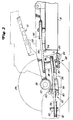
- einen Riemenantrieb für den Frontmäher, wobei sich das Mähwerksgehäuse in einer relativ hohen Schnittstellung befindet,
- Fig. 3
- das Mähwerksgehäuse mit Sekundärriemen in der Draufsicht,
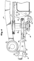
- Fig. 4
- eine ähnliche Ansicht, wie Fig. 2, jedoch das Mähwerksgehäuse in einer mittigen Stellung zeigend, in der Primär- und Sekundärriemen zueinander parallel verlaufen und
- Fig. 5
- eine an das Fahrzeug und an das Mähwerksgehäuse anschließbare Übersetzungsscheibe mit Tragteil.
- Fig. 1
- a front mower in perspective,
- Fig. 2
- a belt drive for the front mower, the mower housing being in a relatively high cutting position,
- Fig. 3
- top view of the mower housing with secondary belt,
- Fig. 4
- a view similar to Fig. 2, but showing the mower housing in a central position, in which the primary and secondary belts are parallel to each other and
- Fig. 5
- a transmission disc with support part that can be connected to the vehicle and the mower housing.
In Fig. 1 der Zeichnung ist ein Fahrzeug in Form eines Kleinschleppers, wie er in der Rasen- und Grundstückspflege eingesetzt wird, mit 10 bezeichnet. Der Kleinschlepper ist deshalb mit einem mit ihm höhenverstellbar verbundenen Rasenmäher ausgerüstet, der von dem Kleinschlepper aus über einen nachfolgend noch im einzelnen zu beschreibenden Riementrieb angetrieben wird.In Fig. 1 of the drawing, a vehicle in the form of a small tractor, as used in lawn and property maintenance, is designated by 10. The small tractor is therefore equipped with a lawn mower that is connected to it in a height-adjustable manner, which is driven by the small tractor via a belt drive to be described in detail below.
Am rückwärtigen Ende des Fahrzeuges befindet sich eine Kraftquelle 12, beispielsweise ein Verbrennungsmotor, die damit hinter einem Bedienungsstand 14 auf dem Kleinschlepper vorgesehen ist. Am vorderen Ende des Schleppers ist ein Mähwerksgehäuse 16 angelenkt, das im Einsatz vor dem Schlepper hergeschoben wird, sich auf vorderen Laufrädern abstützt und in Fig. 3 erkennbare Mähmesser 18 aufnimmt. Im Einsatz laufen die Mähmesser um vertikale Achsen um, um bei Vorwärtsfahrt des Kleinschleppers Rasen oder andere Vegetation schneiden zu können. Das Mähwerksgehäuse 16, ist über Schubarme 20 an das Fahrzeug 10 angelenkt, die im Bereich einer Vorderachse 22 für die vorderen Fahrzeuglaufräder 24 an das Fahrzeug schwenkbar angeschlossen sind. Die derart gebildete Schwenkverbindung 26 ermöglicht es dem Mähwerksgehäuse 16 gegenüber dem Fahrzeug vertikale Relativbewegungen auszuführen, insbesondere wenn über Bodenunebenheiten gefahren werden muß.At the rear end of the vehicle there is a
In herkömmlicher und deshalb in der Zeichnung auch nicht dargestellter Art ist das Mähwerksgehäuse 16 zum Variieren der Schnitthöhe höhenverstellbar angeordnet. Die Höheneinstelleinrichtung erlaubt es einer Bedienungsperson u. a., unterschiedliche Schnitthöhen einzustellen, wobei das Mähwerksgehäuse und damit die Mähmesser in den unterschiedlichen Höheneinstellungen immer in zueinander parallel verlaufenden Horizontalebenen verstellt wird bzw. umlaufen. Eine derartige Höheneinstellung findet sich zum Beispiel an den John Deere F525 Frontmähern.In a conventional manner and therefore not shown in the drawing, the
Beim bevorzugten Ausführungsbeispiel ist das Mähwerksgehäuse mit drei Mähmessern 18 ausgerüstet, und diese werden von dem Verbrennungsmotor 12 aus über eine in den Fig. 2 bis 5 erkennbare Riemengetriebeeinrichtung 18 angetrieben. Im einzelnen erstreckt sich, wie aus Fig. 2 erkennbar ist, vom Verbrennungsmotor 12 aus eine vertikal verlaufende Ausgangswelle 30 nach unten, an deren unterem Ende eine Ausgangsscheibe 32 fest angeordnet ist. Die Ausgangsscheibe ist damit von dem Verbrennungsmotor aus antreibbar und treibt einen endlosen Primärriemen 34 an, der anderenends um die untere Scheibe einer zwei Riemenscheiben aufweisenden Übersetzungsscheibe 36 verläuft und diese antreibt. Von der oberen Scheibe der Übersetzungsscheibe 36 aus wird ein endloser Sekundärriemen 38 angetrieben, der, wie am besten aus Fig. 3 erkennbar ist, um eine Vielzahl von Riemenscheiben 40 geführt ist. Zu diesen gehören auf dem Mähwerksgehäuse 16 angeordnete Riemenleitscheiben 42, von denen eine auch als Spannscheibe für den Sekundärriemen 38 ausgebildet ist. Zu den Riemenscheiben 40 gehören ferner die Mähmesserantriebsscheiben 44, die mit vertikal verlaufenden Messerspindeln 66 fest verbunden sind. Die Mähmesserantriebsscheiben 44 befinden sich in derselben Horizontalebene wie die Riemenleitscheiben, wobei die Messerspindeln 46 sich durch das Mähwerksgehäuse 16 nach unten erstrecken und an ihren unteren Enden die Mähmesser 18 aufnehmen. Damit können die Mähmesser durch die Riemengetriebeeinrichtung 28 angetrieben werden. Bei von dem Verbrennungsmotor 12 aus angetriebener Ausgangsscheibe 32 wird deren Drehbewegung über den Primärriemen 32, die Übersetzungsscheibe 36, den Sekundärriemen 38 und die Mähmesserantriebsscheiben 44 sowie deren Spindeln 46 auf die Mähmesser 18 übertragen.In the preferred exemplary embodiment, the mower housing is equipped with three
Die Riemengetriebeeinrichtung 28 ist derart gestaltet, daß bei Ausweich- oder Relativbewegungen des Mähwerksgehäuses bzw. bei einem Höhenverstellen des Mähwerksgehäuses sich die Winkellage des Primärriemens und/oder des Sekundärriemens nicht extrem verändert. Hierdurch wird eine bessere Kraftübertragung erreicht und ein übermäßiger Verschleiß verhindert. Hierzu ist die Übersetzungsscheibe nicht nur um eine vertikale Achse schwenkbar sondern auch um eine horizontale Achse kippbar angeordnet. Wie im einzelnen aus den Fig. 2 bis 5 ersehen werden kann, ist zwischen dem Mähwerksgehäuse 16 und dem Fahrzeug 10 ein Tragteil 48 vorgesehen. An diesen Tragteil 48 ist ein am besten in Fig. 5 erkennbarer Schwenkarm 50 horizontal schwenkbar angeschlossen, der die Übersetzungsscheibe 36 um eine vertikale Achse drehbar aufnimmt. Der Tragteil 48 und der Schwenkarm 50 tragen damit die Übersetzungsscheibe 36 zwischen dem Mähwerksgehäuse 16 und dem Fahrzeug 10. Die als Spannscheibe ausgebildete Riemenleitscheibe 42 ist auf einem in Fig. 3 dargestellten Schwenkarm angeordnet und steht derart unter der Spannung einer Feder 52, daß der Sekundärriemen 38 gespannt bleibt. Da der Sekundärriemen auch um die Übersetzungsscheibe 36 geführt ist, bewirkt die Feder 52 außerdem, daß der Schwenkarm 50 mit der Übersetzungsscheibe 36 in Richtung auf das Mähwerksgehäuse 16 oder nach vorne verschwenkt oder in diese Richtung gezogen wird, wodurch wiederum der Primärriemen 34 gespannt wird. Eine Scharnierkupplung oder eine erste Schwenkverbindung 54, die ebenfalls in Fig. 5 am besten zu erkennen ist, schließt den Tragteil 48 an das Mähwerksgehäuse 16 an. Durch diese Schwenkverbindung 54 entsteht eine im wesentlichen horizontal und seitlich verlaufende Achse, um die der Tragteil 48 mit Bezug auf das Mähwerksgehäuse 16 schwenken kann, wenn das Mähwerksgehäuse 16 vertikal verstellt wird.The
Eine in den Fig. 2, 4 und 5 eingezeichnete zweite Schwenkverbindung 62 dient zum Anschließen des Tragteils 48 an das Fahrzeug 10. Sie besteht im wesentlichen aus einen Armteil 56, der starr mit dem Tragteil 48 verbunden ist und sich von diesem aus gesehen nach rückwärts erstreckt, und aus einem Befestigungsteil 58, der rückwärtig des Tragteils 48 an das Fahrzeug 10 angeschlossen ist und zwei Stifte 60 aufweist, die zur verschiebbaren Aufnahme des rückwärtigen Abschnittes des Armteils 56 als Lagerrollflächen dienen. Gegebenenfalls kann der Befestigungsteil 58 hierzu an seinem einen Ende U-förmig gerollt sein, wobei die Stifte die beiden Schenkel durchsetzen und in dem Steg eine entsprechende Schlitzöffnung für den Armteil vorgesehen ist. Die Stifte haben einen gegenseitigen Abstand, der in etwa der Höhe des Armteils entspricht, der noch in diesem Bereich mit einer Auskehlung versehen sein kann. Damit wird der Armteil von den Stiften und dem Befestigungsteil in verschiebbarer Form lose getragen. Der Armteil kann sich somit bei relativen Höhenbewegungen des Mähwerksgehäuses gegenüber dem Fahrzeug in Längsrichtung verschieben und auch noch Auf- und Abbewegungen ausführen, was infolge der Auskehlung oder des Abstandes der Stifte oder der Länge der Schlitzöffnung erreicht wird.A
Wenn nun eine Bedienungsperson das Mähwerksgehäuse 16 anhebt, um eine größere Schnitthöhe zu erreichen, dann wird das Mähwerksgehäuse vertikal nach oben mit Bezug auf das Fahrzeug 10 verstellt. Bei einer solchen Verstellung werden auch die Mähwerksgehäusescheiben 40 mit nach oben verstellt, so daß sich ihre Lage mit Bezug auf die Ausgangsscheibe 32 ändert. Gleichzeitig wird bei einer derartigen Verstellung auch die durch die Schwenkverbindung 54 gebildete Achse zusammen mit dem Mähwerksgehäuse 16 nach oben verstellt, so daß auch der vordere an die Schwenkverbindung 54 angeschlossene Abschnitt des Tragteils 48 mit nach oben verstellt wird. Gleichzeitig kippt oder schwenkt der gesamte Tragteil 48 um die Schwenkverbindung 54 nach unten, und zwar in Richtung auf das Mähwerksgehäuse 16, wobei sich der Armteil 56 zwischen den Stiften 60 nach vorne bewegt und leicht nach oben verschwenkt.Now when an operator lifts the
Da auch die Übersetzungsscheibe 36 an dem Tragteil 48 angeordnet ist, wird sie bei einer Höhenbewegung des Mähwerksgehäuses 16 in eine Stellung gemäß Fig. 2 ebenfalls mit Bezug auf das Fahrzeug 10 oder die Ausgangsscheibe 32 höhenverstellt. Sie macht aber nicht die gesamte Höhenbewegung des Mähwerksgehäuses 16 mit, da sie rückwärtig der Schwenkverbindung 54 angeordnet ist und deshalb bei einer solchen Höhenbewegung mit Bezug auf das Mähwerksgehäuse 16 nach unten in eine Schräglage verkippt. Damit ist die Höhenverstellung der Übersetzungsscheibe 36 geringer als die des Mähwerksgehäuses 16 und die Übersetzungsscheibe nimmt eine Höhenlage ein, die zwischen der Ausgangsscheibe 32 und den Mähwerksgehäusescheiben 42 liegt. Durch eine solche Positionierung der Übersetzungsscheibe 36 verändern der Primärriemen 34 und der Sekundärriemen 38 ihre Winkellagen nur in tolerierbaren Grenzen, d. h. die Änderung der Winkel mit Bezug auf die Ausgangsscheibe 32 und der Riemenleitscheiben 42 ist sehr gering, wie es aus Fig. 2 erkennbar ist.Since the
Bei herkömmlichen Riemengetriebeeinrichtungen mit einem Primärriemen und einem Sekundärriemen ist die Übersetzungsscheibe am Mähwerksgehäuse fest angeordnet mit der Folge, daß der Sekundärriemen bei einer Höhenverstellung seine Winkellage nicht ändert.In conventional belt transmission devices with a primary belt and a secondary belt, the transmission pulley is fixed on the mower housing, with the result that the secondary belt does not change its angular position when the height is adjusted.
Der gesamte Höhenunterschied muß deshalb bei solchen Riemengetriebeeinheiten von dem Primärriemen aufgefangen werden. Da andererseits die in der Rasen- und Grundstückspflege einsetzbaren Kleinschlepper sehr gedrungener Bauart sind, ist auch die Übersetzungsscheibe mit relativ kurzem Abstand zur Ausgangsscheibe angeordnet und der Primärriemen muß auf diesem kurzen Abstand die Höhendifferenz überwinden, wobei er sich natürlich sehr stark auslenkt. Bei der Riemengetriebeeinrichtung nach der Erfindung dagegen wird der Abstand der Scheiben, zwischen denen eine Höhendifferenz auszugleichen ist, vergrößert, d. h. durch die Anordnung der Übersetzungsscheibe 36 zwischen den Höhenstellungen der Ausgangsscheibe 32 und den Riemenleitscheiben auf dem Mähwerksgehäuse 16 wird der Längsabstand, der den Riemen 34 und 38 zum Überbrücken der Höhenunterschiede zwischen den Scheiben 32 und 42 zur Verfügung steht, effektiv verlängert. Beim bevorzugten Ausführungsbeispiel steht hierzu der gesamte Abstand zwischen der Ausgangsscheibe 32 und der Riemenleitscheiben 42 zur Verfügung, wie es aus Fig. 2 zu ersehen ist. Da dieser Abstand im Vergleich zu den herkömmlichen Riemengetriebeeinheiten relativ groß ist, ist auch die Riemenauslenkung oder die Veränderung der Winkellagen der beiden Riemen relativ klein.The entire height difference must therefore be absorbed by the primary belt in such belt transmission units. On the other hand, since the small tractors that can be used in lawn and property maintenance are very compact, the transmission pulley is also arranged at a relatively short distance from the output pulley and the primary belt has to overcome the height difference at this short distance, whereby it naturally deflects very strongly. In the belt transmission device according to the invention, on the other hand, the distance between the disks, between which a height difference is to be compensated, is increased, i. H. The arrangement of the
Hinzu kommt noch, daß, wenn das Mähwerksgehäuse angehoben wird, der Tragteil 48 um die Schwenkverbindung 54 verkippt, wobei, wie es in Fig. 2 eingezeichnet ist, die an der Übersetzungsscheibe vorgesehenen Riemenscheiben aus ihrer in Fig. 4 zu ersehenen horizontalen Lage in Richtung auf die Ausgangsscheibe 32 kippen. Dieses Verkippen der Übersetzungsscheibe in einer vertikalen Ebene trägt dazu bei, daß die Riemenscheiben der Übersetzungsscheibe 36 sich stärker zu den Winkellagen der beiden Riemen 34 und 38 ausrichten. Dadurch wiederum werden die Winkellagen des Primärriemens und des Sekundärriemens mit Bezug auf die Riemenscheiben an der Übersetzungsscheibe 36 verkleinert und Abrieb, der infolge von an den Rändern der Riemenscheiben an der Übersetzungsscheibe reibenden Riemen auftreten kann, wird ebenfalls verringert. Es tritt weniger Verschleiß auf.In addition, when the mower housing is raised, the
Beim bevorzugten Ausführungsbeispiel kann die Höhe des Mähwerksgehäuses zwischen 2, 54 cm und 10, 16 cm (1 Zoll und 4 Zoll) eingestellt werden. Bei einer Höheneinstellung von 6, 35 cm (2, 5 Zoll) verlaufen die Riemen in horizontalen Ebenen, und die Riemenscheiben an der Übersetzungsscheibe 36 sind zu der Ausgangsriemenscheibe bzw. zu den Riemenleitscheiben 42 ausgerichtet. Dies ist in Fig. 4 dargestellt. Wird das Mähwerksgehäuse dann aus der Stellung nach Fig. 4 weiter angehoben, dann kippt die Übersetzungsscheibe 36 in Richtung auf die Ausgangsscheibe, wie es vorstehend beschrieben wurde und in Fig. 2 dargestellt ist. Wird das Mähwerksgehäuse 16 andererseits aus seiner in Fig. 4 gezeigten Stellung abgesenkt, dann kippt die Übersetzungsscheibe in entgegengesetzter Richtung, wobei sich wegen des geringeren Höhenunterschiedes die Winkellagen der beiden Riemen kaum ändern, da das Verstellen der Riemenscheiben an der Übersetzungsscheibe 36 aus der horizontalen Lage sehr gering ist.In the preferred embodiment, the height of the mower housing can be set between 2, 54 cm and 10, 16 cm (1 inch and 4 inches). With a height adjustment of 6.35 cm (2.5 inches), the belts run in horizontal planes and the pulleys on the
Bei einem Auftreffen auf Bodenunebenheiten treten zwischen Mähwerksgehäuse 16 und dem Fahrzeug 10 Relativbewegungen auf, wobei sich auch die Schubarme 20 entsprechend verstellen. Aber auch bei solchen Vorgängen werden sich die Winkellagen der beiden Riemen nicht übermäßig verändern. Trifft zum Beispiel das Mähwerk bei Vorwärtsfahrt auf eine Bodenerhebung auf, so verschwenkt das Mähwerksgehäuse 16 zusammen mit den Schubarmen 20 um die Anlenkstelle der Schubarme 20 am Fahrzeug 10 nach oben. Dabei verstellt sich das Mähwerksgehäuse 16 mit Bezug auf die Ausgangsscheibe 32 nach oben und die Winkellagen der beiden Riemen ändern sich in ähnlicher Weise, wie es bei der vorstehend beschriebenen manuellen Höhenänderung erläutert wurde. Die Auslenkungen hängen natürlich von der Höhe der Bodenerhebung ab.When striking uneven ground, relative movements occur between the
Es wurde bereits darauf verwiesen, daß bei dem bevorzugten Ausführungsbeispiel eine erste und eine zweite Schwenkverbindung 54 und 62 vorgesehen sind, wobei die Schwenkverbindung 54 vor und die Schwenkverbindung 62 hinter dem Schwenkanschluß 26 der Schubarme 20 liegt. Durch eine solche Anordnung wird der Tragteil 48 nach oben schwenken, wenn das Mähwerksgehäuse und die Schubarme bei einem Auftreffen auf eine Bodenerhebung nach oben ausweichen, wobei der Schwenkwinkel jedoch nicht dem des Mähwerksgehäuses oder dem der Schubarme entspricht. Der Tragteil 48 wird eine Winkelstellung einnehmen, die zwischen der horizontalen durch die Ausgangsscheiben 32 verlaufenden Ebene und den geneigten Ebenen der Mähwerksgehäusescheiben 40, des Mähwerksgehäuses 16 und der Schubarme 20 liegt. Durch einen angenommenen mittigen Winkel wird die Übersetzungsscheibe 48 nach dem bevorzugten Ausführungsbeispiel die Unfluchtung zwischen den beiden Riemen 34 und 38 halbieren.It has already been pointed out that in the preferred embodiment, a first and a
Bei dem bevorzugten Ausführungsbeispiel ist noch eine Rolle 64 vorgesehen, die von dem Tragteil 48 getragen ist und sich nahe der unteren Kante 66 des Mähwerksgehäuses 16 befindet. Wird das Mähwerksgehäuse 16 für eine niedrige Schnitthöhe eingestellt, dann wird die Rolle 64 zusammen mit dem Tragteil 48 nach oben um die Schwenkverbindung 54 verschwenkt und nach oben mit Bezug auf die untere Kante 66 des Mähwerksgehäuses 16. Bei niedrigen Schnitthöhen tritt der äußere untere Umfang der Rolle 64 kaum über die untere Kante des Mähwerksgehäuses nach unten über und behindert dadurch nicht das Arbeiten bei niedrigen Schnitthöhen. Wird andererseits das Mähwerksgehäuse auf große Schnitthöhen eingestellt, dann schwenkt die Rolle 64 mit dem Tragteil 48 um die Schwenkverbindung 54 nach unten und auch nach unten mit Bezug auf die Bodenkante 66 des Mähwerksgehäuses 16. Bei hohen Schnitthöhen steht damit die Rolle 64 beträchtlich über die untere Kante 66 des Mähwerksgehäuses 16 über, wie es in Fig. 2 gezeigt ist, um bei Bodenunebenheiten zu verhindern, daß die untere Kante des Mähwerksgehäuses über den Boden schleift bzw. die Messer in den Boden schneiden, und um andererseits zu erreichen, daß bei einen Überfahren der Kuppe einer Bodenerhebung das Gras dort nicht unerwünscht kurz geschnitten wird. Die Position der Rolle 64 mit Bezug auf die untere Kante des Mähwerksgehäuses 16 wird automatisch miteingestellt, wenn der Tragteil bei einer Höheneinstellung des Mähwerksgehäuses verstellt wird, so daß die Bedienungsperson die Rolle nicht noch manuell einstellen muß. Herkömmliche Mäher haben eine Rolle oder Rollen, deren Position mit Bezug auf die untere Kante des Mähwerksgehäuses feststehend ist. Eine derartige Position ist auf die unterste Schnitthöhe abgestellt. Bei höheren Schnitthöhen verhindern die herkömmlichen Rollen zwar ein Aufschlagen der unteren Kante auf den Boden, aber nicht, daß bei Bodenunebenheiten deren Kuppe unerwünscht kurz geschnitten wird.In the preferred embodiment, a
Claims (10)
Applications Claiming Priority (2)
| Application Number | Priority Date | Filing Date | Title |
|---|---|---|---|
| US08/057,723 US5361566A (en) | 1993-05-05 | 1993-05-05 | Implement belt drive mechanism |
| US57723 | 2002-01-25 |
Publications (2)
| Publication Number | Publication Date |
|---|---|
| EP0623766A1 true EP0623766A1 (en) | 1994-11-09 |
| EP0623766B1 EP0623766B1 (en) | 1996-03-20 |
Family
ID=22012359
Family Applications (1)
| Application Number | Title | Priority Date | Filing Date |
|---|---|---|---|
| EP94106316A Expired - Lifetime EP0623766B1 (en) | 1993-05-05 | 1994-04-22 | Belt drive for power transmission from a vehicle to a thereto connected device adjustable in height |
Country Status (4)
| Country | Link |
|---|---|
| US (1) | US5361566A (en) |
| EP (1) | EP0623766B1 (en) |
| CA (1) | CA2103229C (en) |
| DE (1) | DE59400163D1 (en) |
Cited By (2)
| Publication number | Priority date | Publication date | Assignee | Title |
|---|---|---|---|---|
| FR2740001A1 (en) * | 1995-10-24 | 1997-04-25 | Techni Ind | Self propelled lawnmower |
| EP1082893A1 (en) * | 1999-09-10 | 2001-03-14 | Deere & Company | Mower and vehicle or apparatus |
Families Citing this family (27)
| Publication number | Priority date | Publication date | Assignee | Title |
|---|---|---|---|---|
| US5865020A (en) * | 1995-11-16 | 1999-02-02 | Exmark Mfg. Co. | Lawn mower having a low center of gravity |
| US6065274A (en) * | 1996-03-12 | 2000-05-23 | Lastec, Inc. | Articulating lawn mowers |
| US5894907A (en) * | 1996-07-12 | 1999-04-20 | Mtd Products Inc. | Asymmetrical drive system |
| US5797251A (en) * | 1997-02-26 | 1998-08-25 | Exmark Mrg. Co., Inc. | Blade drive clutch and brake for a lawn mower |
| US6120401A (en) | 1997-07-29 | 2000-09-19 | Mtd Products Inc | Belt tension mechanism |
| US6312352B1 (en) | 1999-09-10 | 2001-11-06 | Deere & Company | Synchronous belt drive tensioning assembly |
| US6494026B1 (en) | 2001-03-28 | 2002-12-17 | Deere & Company | Vertical belt drive for articulating mower deck |
| US6732828B1 (en) * | 2002-10-22 | 2004-05-11 | Robert Abend | Hydraulically driven vehicle |
| US7028456B2 (en) * | 2003-07-14 | 2006-04-18 | Shivvers Group, Inc. | Mower with flip up mowing deck |
| US6952913B1 (en) | 2004-05-13 | 2005-10-11 | Auburn Consolidated Industries, Inc. | Adjustable belt pulley system |
| US7089722B2 (en) * | 2004-09-30 | 2006-08-15 | Wood-Mizer Products, Inc. | Articulating deck mower with deck height adjuster |
| US20060070365A1 (en) * | 2004-09-30 | 2006-04-06 | Jeff Laskowski | Articulating deck mower with inverted "V" cutter deck arrangement |
| US20060230734A1 (en) * | 2005-04-14 | 2006-10-19 | Deere & Company, A Delaware Corporation | Twin belt mule drive |
| US7665284B1 (en) | 2007-10-16 | 2010-02-23 | Excel Industries, Inc. | Belt drive for lawn mowers |
| EP2910514B1 (en) | 2009-11-18 | 2016-10-19 | Electronic Theatre Controls, Inc. | Lift assembly systems and methods |
| JP5596642B2 (en) * | 2011-08-31 | 2014-09-24 | 株式会社クボタ | Riding mower |
| DE102011117770A1 (en) * | 2011-11-07 | 2013-05-08 | Artur Willibald | vehicle device |
| US9730383B2 (en) * | 2013-03-13 | 2017-08-15 | Husqvarna Ab | Slip controlling belt tension system |
| US9750184B2 (en) * | 2015-12-24 | 2017-09-05 | Kubota Corporation | Mower deck with tilted idle pulleys |
| US9789759B1 (en) | 2016-08-26 | 2017-10-17 | Deere & Company | Zero turning radius mower |
| US10005358B2 (en) | 2016-08-26 | 2018-06-26 | Deere & Company | Zero turning radius mower |
| US11758843B2 (en) | 2016-09-29 | 2023-09-19 | Deere & Company | Mower deck belt tensioning arm |
| JP6698010B2 (en) * | 2016-12-27 | 2020-05-27 | 株式会社クボタ | Riding lawn mower |
| LT3652466T (en) | 2017-07-10 | 2023-09-25 | Liftwave Inc. Dba Rise Robotics | Normalizing tension distribution and minimizing sidewall abrasion within angular drive belt systems |
| US11118321B2 (en) * | 2018-07-10 | 2021-09-14 | Venture Products, Inc. | Unique attachment assembly and method of use |
| US11864492B2 (en) * | 2019-05-03 | 2024-01-09 | Exmark Manufacturing Company Incorporated | Implement drive system and grounds maintenance vehicle incorporating same |
| US11365788B2 (en) * | 2019-10-31 | 2022-06-21 | Deere & Company | Mower drive belt tensioner arm |
Citations (4)
| Publication number | Priority date | Publication date | Assignee | Title |
|---|---|---|---|---|
| US2691421A (en) * | 1950-05-06 | 1954-10-12 | Wind King Electric Mfg Company | Lawn mower wheel drive and control therefor |
| US3464282A (en) * | 1968-06-03 | 1969-09-02 | E T Rugg Co The | V-belt drive having special grooved idler pulley |
| US3969876A (en) * | 1975-04-18 | 1976-07-20 | Mtd Products Inc. | Combination mower and catcher |
| EP0445623A1 (en) * | 1990-03-05 | 1991-09-11 | Deere & Company | Belt transmission for a working tool, especially for a lawnmower connected with a vehicle |
Family Cites Families (7)
| Publication number | Priority date | Publication date | Assignee | Title |
|---|---|---|---|---|
| US3461654A (en) * | 1967-03-15 | 1969-08-19 | M T & D Co The | Mechanism for raising and lowering cutter unit and for concurrently controlling operation of the cutter unit |
| US4120136A (en) * | 1976-12-27 | 1978-10-17 | Massey-Ferguson Inc. | Implement supporting and lifting linkage |
| US4352210A (en) * | 1980-09-12 | 1982-09-28 | General Electric Company | Linear mixer with reduced spurious responses |
| US4813215A (en) * | 1987-05-07 | 1989-03-21 | Simplicity Manufacturing, Inc. | Mower belt transmission with blade brake |
| US4817728A (en) * | 1987-07-23 | 1989-04-04 | Deere & Company | Implement structure for facilitating easy mounting to and disconnection from a lawn and garden tractor |
| US4779406A (en) * | 1987-10-19 | 1988-10-25 | Schroeder Walter J | Mower with tilting mower deck |
| US4914898A (en) * | 1989-04-27 | 1990-04-10 | Deere & Company | V-belt guide |
-
1993
- 1993-05-05 US US08/057,723 patent/US5361566A/en not_active Expired - Lifetime
- 1993-11-16 CA CA002103229A patent/CA2103229C/en not_active Expired - Fee Related
-
1994
- 1994-04-22 EP EP94106316A patent/EP0623766B1/en not_active Expired - Lifetime
- 1994-04-22 DE DE59400163T patent/DE59400163D1/en not_active Expired - Fee Related
Patent Citations (4)
| Publication number | Priority date | Publication date | Assignee | Title |
|---|---|---|---|---|
| US2691421A (en) * | 1950-05-06 | 1954-10-12 | Wind King Electric Mfg Company | Lawn mower wheel drive and control therefor |
| US3464282A (en) * | 1968-06-03 | 1969-09-02 | E T Rugg Co The | V-belt drive having special grooved idler pulley |
| US3969876A (en) * | 1975-04-18 | 1976-07-20 | Mtd Products Inc. | Combination mower and catcher |
| EP0445623A1 (en) * | 1990-03-05 | 1991-09-11 | Deere & Company | Belt transmission for a working tool, especially for a lawnmower connected with a vehicle |
Cited By (2)
| Publication number | Priority date | Publication date | Assignee | Title |
|---|---|---|---|---|
| FR2740001A1 (en) * | 1995-10-24 | 1997-04-25 | Techni Ind | Self propelled lawnmower |
| EP1082893A1 (en) * | 1999-09-10 | 2001-03-14 | Deere & Company | Mower and vehicle or apparatus |
Also Published As
| Publication number | Publication date |
|---|---|
| EP0623766B1 (en) | 1996-03-20 |
| US5361566A (en) | 1994-11-08 |
| DE59400163D1 (en) | 1996-04-25 |
| CA2103229A1 (en) | 1994-11-06 |
| CA2103229C (en) | 1996-01-09 |
Similar Documents
| Publication | Publication Date | Title |
|---|---|---|
| EP0623766B1 (en) | Belt drive for power transmission from a vehicle to a thereto connected device adjustable in height | |
| EP0475021B1 (en) | Mower, especially front-mounted mower | |
| DE2814440A1 (en) | HARVEST MACHINE | |
| DE69824790T2 (en) | Machine with a pivotable relative to the support structure machining unit and pivoting method | |
| EP0807377A2 (en) | Device for connecting a height adjustable implement to a vehicle from a working in a transport position | |
| EP0009134B1 (en) | Rotary mower | |
| EP0933016B1 (en) | Support device and vehicle for ground maintenance | |
| DE102011080385B3 (en) | mower | |
| DE3422254C2 (en) | ||
| DE1782238A1 (en) | Drum or disc grinder | |
| DE1938698A1 (en) | Suspension for a mower unit in an agricultural machine | |
| DE19622452A1 (en) | Lawnmower, e.g. for towing on tractor or excavator | |
| EP0630553A1 (en) | Implement drive for a vehicle-implement combination | |
| DE4108449C2 (en) | ||
| AT501972B1 (en) | MOWER | |
| DE3423410A1 (en) | Front-mounted mower | |
| DE3151481A1 (en) | Agricultural machine | |
| CH444560A (en) | mowing machine | |
| DE2117667A1 (en) | Lawn mower mounted and powered by a vehicle | |
| DE3937110C2 (en) | ||
| DE4105287A1 (en) | DEVICE FOR VEHICLES AND MACHINES | |
| DE10012365C2 (en) | Harrow | |
| DE4019015A1 (en) | Hand-guided mower with rotary blade - has feeler for braking belt drive and tilting arm | |
| EP3735812B1 (en) | Harvester | |
| DE4103011C2 (en) | Mower or hay machine |
Legal Events
| Date | Code | Title | Description |
|---|---|---|---|
| PUAI | Public reference made under article 153(3) epc to a published international application that has entered the european phase |
Free format text: ORIGINAL CODE: 0009012 |
|
| AK | Designated contracting states |
Kind code of ref document: A1 Designated state(s): DE FR GB IT |
|
| 17P | Request for examination filed |
Effective date: 19941020 |
|
| 17Q | First examination report despatched |
Effective date: 19950630 |
|
| GRAA | (expected) grant |
Free format text: ORIGINAL CODE: 0009210 |
|
| AK | Designated contracting states |
Kind code of ref document: B1 Designated state(s): DE FR GB IT |
|
| GBT | Gb: translation of ep patent filed (gb section 77(6)(a)/1977) |
Effective date: 19960321 |
|
| REF | Corresponds to: |
Ref document number: 59400163 Country of ref document: DE Date of ref document: 19960425 |
|
| ET | Fr: translation filed | ||
| ITF | It: translation for a ep patent filed |
Owner name: LENZI & C. |
|
| PLBE | No opposition filed within time limit |
Free format text: ORIGINAL CODE: 0009261 |
|
| STAA | Information on the status of an ep patent application or granted ep patent |
Free format text: STATUS: NO OPPOSITION FILED WITHIN TIME LIMIT |
|
| 26N | No opposition filed | ||
| PGFP | Annual fee paid to national office [announced via postgrant information from national office to epo] |
Ref country code: GB Payment date: 20010322 Year of fee payment: 8 |
|
| PGFP | Annual fee paid to national office [announced via postgrant information from national office to epo] |
Ref country code: FR Payment date: 20010405 Year of fee payment: 8 |
|
| PGFP | Annual fee paid to national office [announced via postgrant information from national office to epo] |
Ref country code: DE Payment date: 20010620 Year of fee payment: 8 |
|
| REG | Reference to a national code |
Ref country code: GB Ref legal event code: IF02 |
|
| PG25 | Lapsed in a contracting state [announced via postgrant information from national office to epo] |
Ref country code: GB Free format text: LAPSE BECAUSE OF NON-PAYMENT OF DUE FEES Effective date: 20020422 |
|
| PG25 | Lapsed in a contracting state [announced via postgrant information from national office to epo] |
Ref country code: DE Free format text: LAPSE BECAUSE OF NON-PAYMENT OF DUE FEES Effective date: 20021101 |
|
| GBPC | Gb: european patent ceased through non-payment of renewal fee |
Effective date: 20020422 |
|
| PG25 | Lapsed in a contracting state [announced via postgrant information from national office to epo] |
Ref country code: FR Free format text: LAPSE BECAUSE OF NON-PAYMENT OF DUE FEES Effective date: 20021231 |
|
| REG | Reference to a national code |
Ref country code: FR Ref legal event code: ST |
|
| PG25 | Lapsed in a contracting state [announced via postgrant information from national office to epo] |
Ref country code: IT Free format text: LAPSE BECAUSE OF NON-PAYMENT OF DUE FEES;WARNING: LAPSES OF ITALIAN PATENTS WITH EFFECTIVE DATE BEFORE 2007 MAY HAVE OCCURRED AT ANY TIME BEFORE 2007. THE CORRECT EFFECTIVE DATE MAY BE DIFFERENT FROM THE ONE RECORDED. Effective date: 20050422 |