EP0933016B1 - Support device and vehicle for ground maintenance - Google Patents
Support device and vehicle for ground maintenance Download PDFInfo
- Publication number
- EP0933016B1 EP0933016B1 EP99101865A EP99101865A EP0933016B1 EP 0933016 B1 EP0933016 B1 EP 0933016B1 EP 99101865 A EP99101865 A EP 99101865A EP 99101865 A EP99101865 A EP 99101865A EP 0933016 B1 EP0933016 B1 EP 0933016B1
- Authority
- EP
- European Patent Office
- Prior art keywords
- cutting unit
- holding device
- vehicle
- support arm
- stop element
- Prior art date
- Legal status (The legal status is an assumption and is not a legal conclusion. Google has not performed a legal analysis and makes no representation as to the accuracy of the status listed.)
- Expired - Lifetime
Links
- 238000012423 maintenance Methods 0.000 title description 12
- 241001417527 Pempheridae Species 0.000 description 3
- 230000005540 biological transmission Effects 0.000 description 3
- 230000006641 stabilisation Effects 0.000 description 3
- 238000011105 stabilization Methods 0.000 description 3
- 239000000969 carrier Substances 0.000 description 2
- 239000000725 suspension Substances 0.000 description 2
- 241001494496 Leersia Species 0.000 description 1
- 230000000712 assembly Effects 0.000 description 1
- 238000000429 assembly Methods 0.000 description 1
- 238000004140 cleaning Methods 0.000 description 1
- 230000003247 decreasing effect Effects 0.000 description 1
- 238000000034 method Methods 0.000 description 1
- 230000002265 prevention Effects 0.000 description 1
- 230000000087 stabilizing effect Effects 0.000 description 1
Images


Classifications
-
- A—HUMAN NECESSITIES
- A01—AGRICULTURE; FORESTRY; ANIMAL HUSBANDRY; HUNTING; TRAPPING; FISHING
- A01D—HARVESTING; MOWING
- A01D34/00—Mowers; Mowing apparatus of harvesters
- A01D34/01—Mowers; Mowing apparatus of harvesters characterised by features relating to the type of cutting apparatus
- A01D34/412—Mowers; Mowing apparatus of harvesters characterised by features relating to the type of cutting apparatus having rotating cutters
- A01D34/42—Mowers; Mowing apparatus of harvesters characterised by features relating to the type of cutting apparatus having rotating cutters having cutters rotating about a horizontal axis, e.g. cutting-cylinders
- A01D34/43—Mowers; Mowing apparatus of harvesters characterised by features relating to the type of cutting apparatus having rotating cutters having cutters rotating about a horizontal axis, e.g. cutting-cylinders mounted on a vehicle, e.g. a tractor, or drawn by an animal or a vehicle
-
- A—HUMAN NECESSITIES
- A01—AGRICULTURE; FORESTRY; ANIMAL HUSBANDRY; HUNTING; TRAPPING; FISHING
- A01B—SOIL WORKING IN AGRICULTURE OR FORESTRY; PARTS, DETAILS, OR ACCESSORIES OF AGRICULTURAL MACHINES OR IMPLEMENTS, IN GENERAL
- A01B73/00—Means or arrangements to facilitate transportation of agricultural machines or implements, e.g. folding frames to reduce overall width
- A01B73/02—Folding frames
- A01B73/04—Folding frames foldable about a horizontal axis
- A01B73/042—Folding frames foldable about a horizontal axis specially adapted for actively driven implements
-
- A—HUMAN NECESSITIES
- A01—AGRICULTURE; FORESTRY; ANIMAL HUSBANDRY; HUNTING; TRAPPING; FISHING
- A01D—HARVESTING; MOWING
- A01D75/00—Accessories for harvesters or mowers
- A01D75/30—Arrangements for trailing two or more mowers
Definitions
- the invention relates to a support device with a support arm, a holding device and an articulated connection, the Support arm on one end with a vehicle and the other over the Articulated connection can be pivotally connected to the holding device is, and with at least a first stop element Secure the position of the holding device, the stop element and the holding device to each other by adjusting the support arm can be created and a property maintenance vehicle with such Carrying device.
- Carriers are usually used on spindle mowers Mowing lawns such as golf courses that are mowed very precisely must be used. These mowers have one at the Carrying device attached cutting unit with a cylindrical Mower spindle with blades on that extend sideways around a Rotate the axis of the cutting spindle.
- US-PS-5,343,680 shows a cylinder mower with several Reel mower cutting units.
- Each reel mower cutting unit is each with a carrying device designed as a yoke over a Articulated connection on a push arm attached to the reel mower appropriate.
- the spindle mower cutting unit Via two plates provided on the carrying device the spindle mower cutting unit can be attached to the push arm in one Mowing position and a folded up maintenance position secured by placing the plates on the hinge in two different positions by means of insertable in openings Bolts can be fixed. In both positions, the Swivel the cylinder mower cutting unit around the articulation.
- the generic US-PS-3,613,340 shows a reel mower with several mowing units, which are swiveled with the cylinder mower around a one extending in the longitudinal direction of the cylinder mower Suspension are swinging connected.
- the swivel arms By means of the swivel arms is a manual lifting of the mower units possible, which by the Swing arms provided stops is limited upwards, whereby a swinging mower unit around the suspension in the raised Position at least in one direction is possible.
- the holding device and that Stop element are against each other by adjusting the support arm can be created, the freedom of movement of the holding device by the system on the stop element is at least restricted.
- the articulated on the support arm holding device can by the Stop element on a swing out in at least one direction be prevented.
- the carrying device also has second stop element and the holding device is between arranged the first and the second stop element, so that the Freedom of movement of the holding device through the stop elements is further limited.
- the stop elements can be arranged in this way that they can be brought into a position in which they can Movement or pivoting of the holding device completely prevention.
- the holding device through the Articulated connection around a horizontal, a vertical or around a Swivel any pivot axis that can be aligned or aligned can. But it is also using an articulated joint several degrees of freedom conceivable, for example by a Ball joint or a universal joint can be realized. Also the Adjustment of the support arm can be done both horizontally or in vertical direction as well as in a combined Direction of movement.
- the vehicle can be a mower like for example a hand-held or hand-pushed mower, such as a lawn mower or a ride on mower, or a lawn tractor, or can also be a sweeper or a snow remover.
- a work unit can be attached, the different positions, for example based on the height above on the ground or on the vehicle, on its central axis or on his direction of travel or similar take or be brought into this can.
- the stabilization or fixing of the holding device is both in a working position and a non-operating position and in particular in a transport position conceivable in which a movement of the holding device is prevented or should only be possible in the given direction.
- This can serve a work unit connected to the holding device to prevent during transport, with the ground or other components of the vehicle to contact Damage to the work unit, the vehicle and its Prevent assemblies or the floor.
- the carrying device can but can also be used to hold the fixture in one Secure work position, for example, to a predetermined one Cutting height above the ground or in relation to the vehicle or to keep its frame and so an even one To achieve work result.
- the stop elements can be arranged opposite one another.
- A has laterally offset arrangement with respect to the holding device the advantage that the holding device through which during the adjustment of the support arm approaching stop elements easily in brought a desired position and safe in this position can be set.
- the Stop element can be firmly attached to the support arm; it is but also an articulated or slidable connection that for certain tasks, for example to adapt to different ones Working units or working heights or similar can be advantageous conceivable.
- the stop element can, however can also be provided removable, so that for example for certain areas of application such as for maintenance or cleaning purposes the holding device in a different position is feasible. This is particularly desirable if at the Holding device mowing units, for example ⁇ in the manner of Spindle mowing units are attached, which are used for maintenance and Adjustment of a lower knife by the support arm preferably be brought into a strongly raised position so that the Underside of the mower units is accessible.
- the actuator is preferably designed as a hydraulic motor, for example by already on the vehicle for other purposes, such as the Drive a work unit, intended pressure source or can be pressurized by its own pressure source. It is also an adjustment using another motor, for example an electric motor. Power transmission too by means of a transmission, such as a belt transmission etc. is possible.
- a manual Adjustment provided for example by means of a crank drive be, preferably if no other energy source is available.
- a secure stabilization of the holding device can be achieved be when at least one of the stop elements one has at least approximately V-shaped surface area. Through the side surfaces of the surface area the Holding device in the direction of the lowest or highest Point, preferably the vertex of the V-shaped surface area, guided, thereby counteracting a lateral Moving is secured.
- At least one of the stop elements is preferably the Articulated connection arranged laterally adjacent. But it is also conceivable, the stop elements in the immediate vicinity of the Provide articulated connection, or the stop elements in arrange a greater distance from the articulation to others To maintain leverage ratios.
- Such support devices can be used on property maintenance vehicles be provided.
- Property maintenance vehicles are, for example Vehicles and equipment for lawn and sports field maintenance or Vehicles such as sweepers, snow clearers or others Vehicles and equipment mainly used for repair and maintenance Maintenance work on private, public, industrial or plots used for other purposes.
- the holding device with a work unit such as one Sweeper roller, a dozer blade or a cutting device etc. connected, it can be in a working or a non-operating position, such as a transport position, be stabilized.
- the work unit is as Cutting unit of a mower executed.
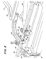
- FIG. 1 a schematic view of an as Real estate maintenance vehicle, in particular as a mower Vehicle 10 shown to which the present invention is adapted for use.
- the driven vehicle 10 has a pair of front wheels 12 touching the ground and a single one Rear wheel 14 on.
- a pair of front cylinder mower cutting units or cutting units 16 and 18 is on the Front of the vehicle 10 attached and a rear Reel mower cutting unit or cutting unit 20 is below of the vehicle 10 between the front wheels 12 and the rear wheel 14 attached.
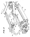
- Each cutting unit 16, 18 and 20 is with a frame 22 of the vehicle 10 via a linkage 24 connected according to the present invention, the one Support arm 26, an articulated connection 28 and a yoke executed holding device 30, as follows is described in more detail.
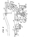
- a right front Cutting unit 16 and a linkage 24 shown in detail is described.
- the frame 22 is a swivel mechanism 32 connected, which has a pair of bearings 34 which the rear end portion 36 of the support arm 26 pivotable take up.
- the bearings 34 define an axis 38 that is based on the mower 10 extends in the longitudinal direction.
- the Support arm 26 is pivotable about this axis 38.
- a couple of Fingers 40 extend downward from support arm 26.
- Actuator 42 designed as a hydraulic motor arranged between the frame 22 and the fingers 40.
- a Operator can move the actuator 42 out and retract, whereby the fingers 40 about the axis 38 of the Pivot mechanism 32 are pivoted and thereby cause the support arm 26 about the axis 38 through the Bearing 34 is determined, pivoted.
- the support arm 26 extends forward and sideways from a centerline of the Vehicle 10 out.
- At the front end region 44 of the support arm 26 is a universal joint or joint connection 28 attached.
- a first or lower stop element 46, the has a V-shaped surface area 48 is also rigidly attached to the front end portion 44 of the bracket 26.
- a pin 50 extending through the hinge 28 is connected to the holding device 30.
- the holding device 30 has a laterally extending central region 52 and a pair of downward and backward extending ones Legs 54 on.
- the lower end portions of the legs 54 are pivotable with the sides of the frame 56 of the cutting unit 16 connected.
- a Hydraulic drive 58 attached to its hydraulic energy obtained from the hydraulic system of the vehicle 10.
- the Hydraulic drive 58 transmits rotational energy in the usual way Way on a cylindrical cutting spindle 60, which in the frame 56th the cutting spindle 16 is arranged.
- Counterweights are on the Hydraulic drive 58 opposite side of the frame 56 attached to the cutting unit 16 from side to side balance.
- a support means 62 is fixed to the frame 22 connected to the vehicle 10 and extends from this Forward.
- a second or upper stop element 64 is fixed connected to the support means 62 and has a V-shaped Surface area 66 on that to the holding device 30, such it is described in more detail below, can be applied.
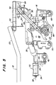
- the Cutting unit 16 is advanced by the holding device 30 pulled, and the holder 30 is generally by the support arm 26 connected to the vehicle 10 to the front pushed or pushed. If bumps occur, it is the one Cutting unit 16 possible over these bumps in the immediate Driving close to the ground surface.
- the swivel device 28, the pivotable connection of the holding device 30 with the cutting unit 16, and the pivoting mechanism 32 of the Support arms 26 on the frame 22 allow the cutting unit 16 to Follow bumps closely in the ground contour.
- the operator can insert the cutting unit 16 into a Raise the transport position as soon as you have a mowing strip has completed and would like to make a U-turn, before making an adjacent strip in the opposite Direction.
- To the cutting unit 16 from the floor in their Raising the transport position extends the operator the actuating means 42, which forces the support arm 26 to its pivoting mechanism 32 for connection to the frame 22 to pivot upwards.
- the support arm 26 goes up pivoted, the front end portion 44 of the Support arm 26 upwards and the lower stop element 46 moves up with. If the front end area 44 of the support arm 26 moves up, the Holding device 30 also move up and the Lift cutting unit 16 off the floor.
- the cutting unit 16 is then tend to swing down and forward when it is lifted off the ground, but a chain 72 that extends extends between the cutting unit 16 and the support arm 26, limits the movement of the cutting unit 16 in this direction.
- the cutting unit 16 When the cutting unit 16 is lifted off the floor, it is standing the cutting unit 16 and the holding device 30 freely, easily from side to side around a forward extending axis, which is determined by the articulation 28 pivot.
- the holding device 30 can abut the V-shaped Surface area 48 of the lower stop element 46 pivot.
- the holding device 30 and the cutting unit 16 are thereby against pivoting in one direction Contact of the holding device 30 on the lower stop element 46 blocked.
- the operator continues the cutting unit 16 raise until the top surface of the holder 30 on the V-shaped surface area 66 of the upper Stop element 64 abuts.
- the linkage 24 will then generally prevented from moving further upward.
- the lower and upper stop members 46 and 64 help certain V-shaped surface areas 48 and 66 doing the holding device 30 in one by the V-shaped Surface areas 48 and 66 to perform certain notch 74 and to center. If the holding device 30 and the Cutting unit 16 are raised when the holding device 30 on a flat area 76 of the stop element 46 and 64 is applied, the holding device 30 along the flat Surface 76 in the deepest position of the valley or notch 74 through the V-shaped surface areas 48 and 66 is determined to slide.
- the V-shaped surface areas 48 and 66 also help to secure the fixture 30 in place safely in a single position at the lowest point or Notch 74 of V-shaped surface areas 48 and 66 too hold once the cutting unit 16 is fully in its Transport position is raised.
- the holding device 30 and the cutting unit 16 With the support arm 26 in the raised position and the Holding device 30 in contact with the lower and the upper Stop element 66 and 46, the holding device 30 and the cutting unit 16 generally from a pivoting of Held side to side around the link 28.
- the Articulation 28 and the upper and lower Stop element 64 and 46 determine three points at which the Movement of the holding device 30 is limited. These three Dots serve together with the V-shaped surface areas 48 and 66 of the stop elements 46 and 64, the Holding device 30 generally on a pivoting around the To prevent articulation 28.
- the holding device 30 and the Cutting unit 16 are thereby pivoted from the side held to the side when the operator held the Raises cutting unit 16 into the transport position.
- the holding device 30 generally in its position, what generally prevents the cutting unit 16 from doing so centrifugal force occurring during the turn down in To pivot contact with the ground. All cutting units 16, 18 and 20 are kept at a uniform height and the cutting units 16, 18, 20 are generally thereof prevented from pivoting in contact with side slopes, while being held in the transport position. The Cutting units 16, 18 and 20 and the holding devices 30 are also in contact with the Underside of the vehicle 10 prevented when the cutting units 16, 18 and 20 held in the transport position become.
- the cutting unit 16 opens bring the ground back to normal mowing the operator will operate the controller, to allow hydraulic pressure from actuator 42 to be relieved.
- the weight of the cutting unit 16 is the Swivel the support arm 26 down and the hydraulic medium out force the actuator 42 until the rollers 68 and 70 open the floor surface come to rest.
- the lower stop element 46 supports the holding device 30 when the cutting unit 16 begins to sink and prevents it Holding device 30 generally attached to it during the lowering process to pivot strongly in one direction.
- the cutting unit 16 will therefore be approximately horizontal, so that the outer edges of the cutting unit 16 not the lawn surface Hollow out or damage severely if the cutting unit 16 touches the ground.
Description
Die Erfindung betrifft eine Tragvorrichtung mit einem Tragarm, einer Halteeinrichtung und einer Gelenkverbindung, wobei der Tragarm einenends mit einem Fahrzeug und andernends über die Gelenkverbindung mit der Halteeinrichtung schwenkbar verbindbar ist, und mit zumindest einem ersten Anschlagelement zur Lagesicherung der Halteeinrichtung, wobei das Anschlagelement und die Halteeinrichtung durch eine Verstellung des Tragarms aneinander anlegbar sind und ein Grundstückspflegefahrzeug mit einer solchen Tragvorrichtung.The invention relates to a support device with a support arm, a holding device and an articulated connection, the Support arm on one end with a vehicle and the other over the Articulated connection can be pivotally connected to the holding device is, and with at least a first stop element Secure the position of the holding device, the stop element and the holding device to each other by adjusting the support arm can be created and a property maintenance vehicle with such Carrying device.
Tragvorrichtungen werden üblicherweise an Spindelmähgeräten zum Mähen von Rasengeländen wie Golfplätzen, die sehr genau gemäht werden müssen, verwendet. Diese Mähgeräte weisen eine an der Tragvorrichtung angebrachte Schneideinheit mit einer zylindrischen Mähspindel mit Klingen auf, die um eine sich seitwärts erstreckende Achse der Mähspindel rotieren.Carriers are usually used on spindle mowers Mowing lawns such as golf courses that are mowed very precisely must be used. These mowers have one at the Carrying device attached cutting unit with a cylindrical Mower spindle with blades on that extend sideways around a Rotate the axis of the cutting spindle.
Die US-PS-5,343,680 zeigt einen Spindelmäher mit mehreren Spindelmäherschneideinheiten. Jede Spindelmäherschneideinheit ist mit jeweils einer als Joch ausgeführten Tragvorrichtung über eine Gelenkverbindung an einem an dem Spindelmäher angebrachten Schubarm angebracht. Über zwei an der Tragvorrichtung vorgesehene Platten kann die Spindelmäherschneideinheit an dem Schubarm in einer Mähstellung und einer hochgeklappten Wartungsstellung gesichert werden, indem die Platten an der Gelenkverbindung in zwei unterschiedlichen Stellungen mittels in Öffnungen einsteckbarer Bolzen festgelegt werden können. In beiden Stellungen kann die Spindelmäherschneideinheit um die Gelenkverbindung verschwenken.US-PS-5,343,680 shows a cylinder mower with several Reel mower cutting units. Each reel mower cutting unit is each with a carrying device designed as a yoke over a Articulated connection on a push arm attached to the reel mower appropriate. Via two plates provided on the carrying device the spindle mower cutting unit can be attached to the push arm in one Mowing position and a folded up maintenance position secured by placing the plates on the hinge in two different positions by means of insertable in openings Bolts can be fixed. In both positions, the Swivel the cylinder mower cutting unit around the articulation.
Die gattungsgemäße US-PS-3,613,340 zeigt einen Spindelmäher mit mehreren Mäheinheiten, welche über Schwenkarme mit dem Spindelmäher um eine sich in Längsrichtung des Spindelmähers erstreckende Aufhängung pendelnd verbunden sind. Mittels der Schwenkarme ist ein manuelles Anheben der Mäheinheiten möglich, welches durch an den Schwenkarmen vorgesehene Anschläge nach oben begrenzt wird, wobei ein Pendelnder Mäheinheiten um die Aufhängung in der angehobenen Stellung zumindest in einer Richtung möglich ist. The generic US-PS-3,613,340 shows a reel mower with several mowing units, which are swiveled with the cylinder mower around a one extending in the longitudinal direction of the cylinder mower Suspension are swinging connected. By means of the swivel arms is a manual lifting of the mower units possible, which by the Swing arms provided stops is limited upwards, whereby a swinging mower unit around the suspension in the raised Position at least in one direction is possible.
Das der Erfindung zugrunde liegende Problem wird in der nicht optimalen Funktion bekannter Tragvorrichtungen und der mit solchen Tragvorrichtungen ausgestatteten Grundstückspflegefahrzeuge gesehen.The problem underlying the invention is not in the optimal function of known carriers and with such Carriage-equipped property maintenance vehicles seen.
Dieses Problem wird erfindungsgemäß durch die Lehre der Patentansprüche
1 und 9 gelöst, wobei in den weiteren Patentansprüchen
die Lösung in vorteilhafter Weise weiterentwickelnde Merkmal
aufgeführt sind.This problem is solved according to the invention by the teaching of the
Auf diese Weise kann eine Lagesicherung oder Stabilisierung der Halteeinrichtung erfolgen. Die Halteeinrichtung und das Anschlagelement sind durch eine Verstellung des Tragarms aneinander anlegbar, wobei die Bewegungsfreiheit der Halteeinrichtung durch die Anlage an dem Anschlagelement zumindest eingeschränkt wird. Die gelenkig an dem Tragarm angebrachte Halteeinrichtung kann durch das Anschlagelement an einem Ausschwenken in zumindest einer Richtung gehindert werden. Die Tragvorrichtung weist darüber hinaus ein zweites Anschlagelement auf und die Halteeinrichtung ist zwischen dem ersten und dem zweiten Anschlagelement angeordnet, so dass die Bewegungsfreiheit der Halteeinrichtung durch die Anschlagelemente weiter begrenzt wird. Die Anschlagelemente können derart angeordnet werden, daß sie in eine Lage bringbar sind, in der sie eine Bewegung oder ein Verschwenken der Halteeinrichtung vollständig unterbinden. Es ist denkbar, daß die Halteeinrichtung durch die Gelenkverbindung um eine horizontale, eine vertikale oder um eine beliebig ausgerichtete oder ausrichtbare Schwenkachse verschwenken kann. Es ist aber auch die Verwendung einer Gelenkverbindung mit mehreren Freiheitsgraden denkbar, was beispielsweise durch ein Kugelgelenk oder ein Kardangelenk realisiert werden kann. Auch die Verstellung des Tragarms kann sowohl in horizontaler oder in vertikaler Richtung als auch in einer kombinierten Bewegungsrichtung erfolgen. Das Fahrzeug kann ein Mähgerät, wie beispielsweise ein handgeführtes oder handgeschobenes Mähgerät, wie ein Rasenmäher oder ein Aufsitzmäher, oder ein Rasentraktor, oder auch eine Kehrmaschine oder ein Schneeräumgerät sein. Allgemein ausgedrückt handelt es sich vorzugsweise um ein Fahrzeug an dem mittels der an dem Tragarm verschwenkbar angeordneten Halteeinrichtung eine Arbeitseinheit anbringbar ist, die verschiedene Stellungen beispielsweise bezogen auf die Höhe über dem Boden oder auf das Fahrzeug, auf seine Mittelachse oder auf seine Fahrtrichtung o.ä. einnehmen bzw. in diese gebracht werden kann. Die Stabilisierung bzw. Festlegung der Halteeinrichtung ist sowohl in einer Arbeitsstellung wie auch einer AußerBetriebsstellung und dabei insbesondere in einer Transportstellung vorstellbar, bei der eine Bewegung der Halteeinrichtung unterbunden oder nur in vorgegebener Richtung ermöglicht sein soll. Dies kann dazu dienen, eine an der Halteeinrichtung angeschlossene Arbeitseinheit während des Transports daran zu hindern, mit dem Boden oder anderen Baugruppen des Fahrzeugs in Kontakt zu treten, um Beschädigungen der Arbeitseinheit, des Fahrzeugs und seiner Baugruppen oder des Bodens vorzubeugen. Die Tragvorrichtung kann aber auch verwendet werden, um die Halteeinrichtung in einer Arbeitsstellung zu sichern, beispielsweise um eine vorgegebene Schnitthöhe über dem Boden oder bezogen auf das Fahrzeug oder seinen Rahmen einzuhalten und um so ein gleichmäßiges Arbeitsergebnis zu erzielen.In this way, securing the position or stabilizing the Holding device done. The holding device and that Stop element are against each other by adjusting the support arm can be created, the freedom of movement of the holding device by the system on the stop element is at least restricted. The articulated on the support arm holding device can by the Stop element on a swing out in at least one direction be prevented. The carrying device also has second stop element and the holding device is between arranged the first and the second stop element, so that the Freedom of movement of the holding device through the stop elements is further limited. The stop elements can be arranged in this way that they can be brought into a position in which they can Movement or pivoting of the holding device completely prevention. It is conceivable that the holding device through the Articulated connection around a horizontal, a vertical or around a Swivel any pivot axis that can be aligned or aligned can. But it is also using an articulated joint several degrees of freedom conceivable, for example by a Ball joint or a universal joint can be realized. Also the Adjustment of the support arm can be done both horizontally or in vertical direction as well as in a combined Direction of movement. The vehicle can be a mower like for example a hand-held or hand-pushed mower, such as a lawn mower or a ride on mower, or a lawn tractor, or can also be a sweeper or a snow remover. Generally expressed, it is preferably a vehicle on the by means of the pivotally arranged on the support arm Holding device a work unit can be attached, the different positions, for example based on the height above on the ground or on the vehicle, on its central axis or on his direction of travel or similar take or be brought into this can. The stabilization or fixing of the holding device is both in a working position and a non-operating position and in particular in a transport position conceivable in which a movement of the holding device is prevented or should only be possible in the given direction. This can serve a work unit connected to the holding device to prevent during transport, with the ground or other components of the vehicle to contact Damage to the work unit, the vehicle and its Prevent assemblies or the floor. The carrying device can but can also be used to hold the fixture in one Secure work position, for example, to a predetermined one Cutting height above the ground or in relation to the vehicle or to keep its frame and so an even one To achieve work result.
Wird das erste Anschlagelement unterhalb der Halteeinrichtung angeordnet, so kann sich die Halteeinrichtung bedingt durch ihre Gewichtskraft bzw. bedingt durch die Gewichtskraft einer an ihr angebrachten Arbeitseinheit an dem Anschlagelement anlegen bzw. sich auf ihm abstützen, wodurch beispielsweise eine durch die Gewichtskraft bedingte Bewegung, wie beispielsweise ein Verschwenken nach unten, unterbunden werden kann.Will the first stop element below the holding device arranged, so the holding device due to their Weight force or due to the weight of one on it place the attached work unit on the stop element or lean on him, for example, one by Weight-related movement, such as a Swiveling down, can be prevented.
Die Anschlagelemente können gegenüberliegend angeordnet sein. Eine bezogen auf die Halteeinrichtung seitlich versetzte Anordnung weist den Vorteil auf, daß die Halteeinrichtung durch die sich während des Verstellens des Tragarms annähernden Anschlagelemente leicht in eine gewünschte Stellung gebracht und in dieser Stellung sicher festgelegt werden kann.The stop elements can be arranged opposite one another. A has laterally offset arrangement with respect to the holding device the advantage that the holding device through which during the adjustment of the support arm approaching stop elements easily in brought a desired position and safe in this position can be set.
Ist wenigstens eines der Anschlagelemente mit dem Tragarm mitteloder unmittelbar verbunden, so wird es bei einer Verstellung des Tragarms durch diesen bewegt und kann so an die Halteeinrichtung herangeführt und mit dieser in Anlage gebracht werden. Das Anschlagelement kann an dem Tragarm fest angebracht sein; es ist aber auch eine gelenkige oder verschiebbare Verbindung, die für bestimmte Aufgaben, beispielsweise zur Anpassung an verschiedene Arbeitseinheiten oder Arbeitshöhen o.ä., vorteilhaft sein kann, denkbar. Is at least one of the stop elements with the support arm medium or directly connected, it will be when the Carrier arm moved by this and can be attached to the holding device introduced and brought into contact with this. The Stop element can be firmly attached to the support arm; it is but also an articulated or slidable connection that for certain tasks, for example to adapt to different ones Working units or working heights or similar can be advantageous conceivable.
Ist zumindest eines der Anschlagelemente mit einem Rahmen des Fahrzeugs mittel- oder unmittelbar verbunden, so kann es einen bezogen auf das Fahrzeug lagefesten Anschlag bieten, der beispielsweise zur Stabilisierung der Halteeinrichtung in einer gewünschten Arbeits- oder Transporthöhe oder -stellung dienen kann. Es ist denkbar, dieses Anschlagelement dauerhaft an dem Rahmen des Fahrzeugs anzubringen. Das Anschlagelement kann aber auch abnehmbar vorgesehen sein, so daß beispielsweise für bestimmte Einsatzgebiete wie zu Wartungs- oder Reinigungszwecken die Halteeinrichtung in eine abweichende Stellung bringbar ist. Dies ist besonders wünschenswert, wenn an der Halteeinrichtung Mäheinheiten, beispielsweise · in der Art von Spindelmäheinheiten, angebracht sind, die zur Wartung und zur Einstellung eines Untermessers durch den Tragarm vorzugsweise in eine stark angehobene Stellung gebracht werden, so daß die Unterseite der Mäheinheiten zugänglich wird.Is at least one of the stop elements with a frame of the Vehicle directly or indirectly connected, so it can be in relation to the vehicle offer a fixed stop, the for example to stabilize the holding device in a desired working or transport height or position can. It is conceivable to permanently attach this stop element to the Attach the frame of the vehicle. The stop element can, however can also be provided removable, so that for example for certain areas of application such as for maintenance or cleaning purposes the holding device in a different position is feasible. This is particularly desirable if at the Holding device mowing units, for example · in the manner of Spindle mowing units are attached, which are used for maintenance and Adjustment of a lower knife by the support arm preferably be brought into a strongly raised position so that the Underside of the mower units is accessible.
Es ist vorteilhaft, den Tragarm an dem Rahmen in vertikaler Richtung mittels eines Betätigungsmittels verstellbar anzubringen, so daß der Tragarm und damit die Halteeinrichtung und eventuell auch zumindest eines der Anschlagelemente in unterschiedliche Vertikalstellungen gebracht und die Halteeinrichtung beispielsweise in einer erhöhten oder abgesenkten Stellung gesichert werden kann. Das Betätigungsmittel ist vorzugsweise als ein Hydraulikmotor ausgeführt, der beispielsweise durch eine bereits am Fahrzeug für andere Zwecke, wie den Antrieb einer Arbeitseinheit, vorgesehene Druckquelle oder durch eine eigene Druckquelle mit Druck beaufschlagbar ist. Es ist aber auch eine Verstellung mittels eines anderen Motors, beispielsweise eines Elektromotors, denkbar. Auch die Kraftübertragung mittels eines Getriebes, wie eines Riemengetriebes etc. ist möglich. Darüber hinaus kann auch eine manuelle Verstellung beispielsweise mittels eines Kurbelantriebs vorgesehen sein, vorzugsweise dann, wenn keine andere Energiequelle zur Verfügung steht. It is advantageous to mount the support arm on the frame in a vertical position Direction adjustable by means of an actuator to attach, so that the support arm and thus the holding device and possibly also at least one of the stop elements in brought different vertical positions and the holding device for example in an increased or decreased Position can be secured. The actuator is preferably designed as a hydraulic motor, for example by already on the vehicle for other purposes, such as the Drive a work unit, intended pressure source or can be pressurized by its own pressure source. It is also an adjustment using another motor, for example an electric motor. Power transmission too by means of a transmission, such as a belt transmission etc. is possible. In addition, a manual Adjustment provided for example by means of a crank drive be, preferably if no other energy source is available.
Eine sichere Stabilisierung der Halteeinrichtung kann erzielt werden, wenn zumindest eines der Anschlagelemente einen zumindest annähernd V-förmigen Oberflächenbereich aufweist. Durch die Seitenflächen des Oberflächenbereichs wird die Halteeinrichtung in Richtung des tiefsten bzw. höchsten Punktes, vorzugsweise des Scheitelpunkts des V-förmigen Oberflächenbereichs, geführt, wodurch sie gegen ein seitliches Verschieben gesichert wird.A secure stabilization of the holding device can be achieved be when at least one of the stop elements one has at least approximately V-shaped surface area. Through the side surfaces of the surface area the Holding device in the direction of the lowest or highest Point, preferably the vertex of the V-shaped surface area, guided, thereby counteracting a lateral Moving is secured.
Vorzugsweise ist zumindest eines der Anschlagelemente der Gelenkverbindung seitwärts benachbart angeordnet. Es ist aber auch denkbar, die Anschlagelemente in unmittelbarer Nähe der Gelenkverbindung vorzusehen, oder die Anschlagelemente in größerem Abstand zu der Gelenkverbindung anzuordnen, um andere Hebelverhältnisse zu erhalten.At least one of the stop elements is preferably the Articulated connection arranged laterally adjacent. But it is also conceivable, the stop elements in the immediate vicinity of the Provide articulated connection, or the stop elements in arrange a greater distance from the articulation to others To maintain leverage ratios.
Solche Tragvorrichtungen können an Grundstückspflegefahrzeugen vorgesehen sein. Grundstückspflegefahrzeuge sind beispielsweise Fahrzeuge und Geräte zur Rasen- und Sportplatzpflege oder aber Fahrzeuge wie Kehrmaschinen, Schneeräumgeräte oder andere Fahrzeuge und Geräte, die hauptsächlich zu Instandsetzungs- und Wartungsarbeiten auf privaten, öffentlichen, industriell oder anderweitig genutzten Grundstücken eingesetzt werden.Such support devices can be used on property maintenance vehicles be provided. Property maintenance vehicles are, for example Vehicles and equipment for lawn and sports field maintenance or Vehicles such as sweepers, snow clearers or others Vehicles and equipment mainly used for repair and maintenance Maintenance work on private, public, industrial or plots used for other purposes.
Wird die Halteeinrichtung mit einer Arbeitseinheit wie einer Kehrwalze, einem Räumschild oder einer Schneideinrichtung etc. verbunden, so kann diese in einer Arbeits- oder einer AußerBetriebsstellung, wie beispielsweise einer Transportstellung, stabilisiert werden. Vorzugsweise ist die Arbeitseinheit als Schneideinheit eines Mähgeräts ausgeführt. Durch die Stabilisierung der Schneideinheit kann, besonders bei einer Festlegung in einer erhöhten Transportstellung, Beschädigungen des Rasens oder der Schneideinheit durch ein Auftreffen der Schneideinheit auf den Untergrund während des Transports, beispielsweise in Kurven oder während Kehrtwendungen, vorgebeugt werden. If the holding device with a work unit such as one Sweeper roller, a dozer blade or a cutting device etc. connected, it can be in a working or a non-operating position, such as a transport position, be stabilized. Preferably, the work unit is as Cutting unit of a mower executed. Through the Stabilization of the cutting unit can, especially with a Fixing in an elevated transport position, damage of the lawn or the cutting unit by hitting the Cutting unit on the ground during transport, for example in curves or during U-turns, be prevented.
In der Zeichnung ist ein nachfolgend näher beschriebenes Ausführungsbeispiel der Erfindung dargestellt. Es zeigt:
- Fig. 1
- eine schematische Draufsicht auf ein Fahrzeug mit zwei vorderen und einer rückwärtigen Schneideinheit,
- Fig. 2
- eine Ausschnittsansicht der vorderen bezogen auf die Fahrtrichtung des Fahrzeugs rechten Schneideinheit mit einer erfindungsgemäßen Tragvorrichtung,
- Fig. 3
- eine perspektivische Darstellung der bezogen auf die Fahrtrichtung linken, vorderen Schneideinheit,
- Fig. 4
- eine Seitenansicht der rechten, vorderen Schneideinheit in der Betriebsstellung,
- Fig. 5
- eine Seitenansicht der rechten vorderen Schneideinheit in der Transportstellung und
- Fig. 6
- eine perspektivische Seitenansicht von der bezogen auf die Fahrtrichtung linken Seite des Fahrzeugs auf die rückwärtige Schneideinheit mit einer erfindungsgemäßen Tragvorrichtung.
- Fig. 1
- 1 shows a schematic top view of a vehicle with two front and one rear cutting unit,
- Fig. 2
- 3 shows a cutout view of the front cutting unit with respect to the direction of travel of the vehicle with a carrying device according to the invention,
- Fig. 3
- 1 shows a perspective illustration of the front cutting unit on the left in relation to the direction of travel
- Fig. 4
- a side view of the right front cutting unit in the operating position,
- Fig. 5
- a side view of the right front cutting unit in the transport position and
- Fig. 6
- a perspective side view of the left side of the vehicle in relation to the direction of travel to the rear cutting unit with a carrying device according to the invention.
Mit Bezug auf Figur 1 wird eine schematische Ansicht eines als
Grundstückspflegefahrzeug, insbesondere als Mähgerät, ausgeführten
Fahrzeugs 10 gezeigt, an das die vorliegende Erfindung
zur Benutzung angepaßt ist. Das angetriebene Fahrzeug 10 weist
ein Paar den Boden berührender Vorderräder 12 und ein einzelnes
Hinterrad 14 auf. Ein Paar vorderer Spindelmäherschneideinheiten
bzw. Schneideinheiten 16 und 18 ist an der
Vorderseite des Fahrzeugs 10 angebracht und eine rückwärtige
Spindelmäherschneideinheit bzw. Schneideinheit 20 ist unterhalb
des Fahrzeugs 10 zwischen den Vorderrädern 12 und dem
rückwärtigen Rad 14 angebracht. Jede Schneideinheit 16, 18 und
20 ist mit einem Rahmen 22 des Fahrzeugs 10 über ein Gestänge
24 entsprechend der vorliegenden Erfindung verbunden, das einen
Tragarm 26, eine Gelenkverbindung 28 und eine als Joch
ausgeführte Halteeinrichtung 30 aufweist, wie es im folgenden
genauer beschrieben wird.With reference to Figure 1, a schematic view of an as
Real estate maintenance vehicle, in particular as a
Mit Bezug auf die Figuren 2 und 4 wird eine rechte vordere
Schneideinheit 16 und ein Gestänge 24 gezeigt, das im Detail
beschrieben wird. Mit dem Rahmen 22 ist ein Schwenkmechanismus
32 verbunden, der ein Paar von Lagern 34 aufweist, welche den
rückwärtigen Endbereich 36 des Tragarms 26 schwenkbar
aufnehmen. Die Lager 34 bestimmen eine Achse 38, die sich
bezogen auf das Mähgerät 10 in Längsrichtung erstreckt. Der
Tragarm 26 ist um diese Achse 38 verschwenkbar. Ein Paar von
Fingern 40 erstreckt sich von dem Tragarm 26 nach unten. Ein
als Hydraulikmotor ausgeführtes Betätigungsmittel 42 ist
zwischen dem Rahmen 22 und den Fingern 40 angeordnet. Eine
Bedienungsperson kann das Betätigungsmittel 42 aus- und
einfahren, wodurch die Finger 40 um die Achse 38 des
Verschwenkmechanismus 32 verschwenkt werden und dadurch
verursachen, daß der Tragarm 26 um die Achse 38, die durch die
Lager 34 bestimmt wird, verschwenkt. Der Tragarm 26 erstreckt
sich nach vorne und seitlich von einer Mittellinie des
Fahrzeugs 10 aus. An dem vorderen Endbereich 44 des Tragarms 26
ist ein Universalgelenk bzw. eine Gelenkverbindung 28
befestigt. Ein erstes oder unteres Anschlagelement 46, das
einen V-förmigen Oberflächenbereich 48 aufweist, ist ebenfalls
steif an dem vorderen Endbereich 44 des Tragarms 26 befestigt.
Ein Stift 50, der sich durch die Gelenkverbindung 28 erstreckt,
ist mit der Halteeinrichtung 30 verbunden. Die Halteeinrichtung
30 weist einen sich seitwärts erstreckenden Zentralbereich 52
und ein Paar von sich nach unten und rückwärts erstreckenden
Schenkeln 54 auf. Die unteren Endbereiche der Schenkel 54 sind
schwenkbar mit den Seiten des Rahmens 56 der Schneideinheit 16
verbunden. An dem rechten Seitenbereich des Rahmens 56 ist ein
Hydraulikantrieb 58 angebracht, der seine hydraulische Energie
von dem Hydrauliksystem des Fahrzeugs 10 erhält. Der
Hydraulikantrieb 58 überträgt Rotationsenergie in üblicher
Weise auf eine zylindrische Mähspindel 60, die in dem Rahmen 56
der Mähspindel 16 angeordnet ist. Gegengewichte sind an der dem
Hydraulikantrieb 58 gegenüberliegenden Seite des Rahmens 56
angebracht, um die Schneideinheit 16 von Seite zu Seite
auszubalancieren. Ein Stützmittel 62 ist fest mit dem Rahmen 22
des Fahrzeugs 10 verbunden und erstreckt sich von diesem aus
nach vorne. Ein zweites oder oberes Anschlagelement 64 ist fest
mit dem Stützmittel 62 verbunden und weist einen V-förmigen
Oberflächenbereich 66 auf, der an die Halteeinrichtung 30, wie
es im folgenden genauer beschrieben wird, anlegbar ist.With reference to Figures 2 and 4, a right
Als nächstes wird die Arbeitsweise der vorliegenden Erfindung
anhand der rechten vorderen Schneideinheit 16 genauer
beschrieben werden. Während des normalen Mähbetriebs befindet
sich die rechte vordere Schneideinheit 16 in der in Fig. 4
gezeigten Stellung. In diesem Betriebszustand ist das Betätigungsmittel
42 im allgemeinen von dem Hydraulikdruck entlastet,
und dem Tragarm 26 ist es daher erlaubt, unter dem Gewicht der
Schneideinheit 16, die an den vorderen Endbereich 44 des
Tragarms 26 angeschlossen ist, nach unten zu schwenken. Vordere
und rückwärtige Rollen 68 und 70, die an der Schneideinheit 16
angebracht sind, rollen in Kontakt mit dem Boden, um die
Schneideinheit 16 in der gewünschten Höhe über dem Boden zu
stützen, um dabei der Mähspindel 60 und einem Untermesser zu
erlauben, Gras in der gewünschten Höhe zu schneiden. Die
Schneideinheit 16 wird durch die Halteeinrichtung 30 vorwärts
gezogen, und die Halteeinrichtung 30 wird im allgemeinen durch
den mit dem Fahrzeug 10 verbundenen Tragarm 26 nach vorne
geschoben oder gedrückt. Wenn Bodenwellen auftreten, ist es der
Schneideinheit 16 möglich, über diese Bodenwellen in unmittelbarer
Nähe zu der Bodenoberfläche zu fahren. Die Schwenkvorrichtung
28, die schwenkbare Verbindung der Halteeinrichtung 30
mit der Schneideinheit 16, und der Verschwenkmechanismus 32 des
Tragarms 26 am Rahmen 22 erlauben es der Schneideinheit 16, den
Bodenwellen in der Bodenkontur eng zu folgen. Next, the operation of the present invention
based on the right
Die Bedienungsperson kann die Schneideinheit 16 in eine
Transportstellung anheben, sowenn sie einen Mähstreifen
fertiggestellt hat und eine Kehrtwendung ausführen möchte,
bevor sie einen angrenzenden Streifen in der entgegengesetzten
Richtung ausführt. Um die Schneideinheit 16 vom Boden in ihre
Transportstellung anzuheben, verlängert die Bedienungsperson
das Betätigungsmittel 42, was den Tragarm 26 dazu zwingt, um
seinen Verschwenkmechanismus 32 zur Verbindung mit dem Rahmen
22 nach oben zu verschwenken. Wenn der Tragarm 26 nach oben
verschwenkt, verschiebt sich der vordere Endbereich 44 des
Tragarms 26 nach oben und das untere Anschlagelement 46
verschiebt sich mit nach oben. Wenn sich der vordere Endbereich
44 des Tragarms 26 nach oben verschiebt, wird sich die
Halteeinrichtung 30 ebenfalls nach oben verschieben und die
Schneideinheit 16 vom Boden heben. Die Schneideinheit 16 wird
dann dazu neigen, nach unten und nach vorne zu schwenken, wenn
sie vom Boden abgehoben ist, aber eine Kette 72, die sich
zwischen der Schneideinheit 16 und dem Tragarm 26 erstreckt,
begrenzt die Bewegung der Schneideinheit 16 in dieser Richtung.
Wenn die Schneideinheit 16 vom Boden abgehoben ist, steht es
der Schneideinheit 16 und der Halteeinrichtung 30 frei, leicht
von Seite zu Seite um eine sich nach vorne erstreckende Achse,
die durch die Gelenkverbindung 28 bestimmt wird, zu
verschwenken. Wenn die Bedienungsperson die Schneideinheit 16
anhebt, kann die Halteeinrichtung 30 in Anlage an den V-förmigen
Oberflächenbereich 48 des unteren Anschlagelements 46
verschwenken. Die Halteeinrichtung 30 und die Schneideinheit 16
sind dadurch gegen ein Verschwenken in einer Richtung durch
Anlage der Halteeinrichtung 30 an dem unteren Anschlagelement
46 blockiert. Die Bedienungsperson fährt fort, die Schneideinheit
16 anzuheben, bis die obere Oberfläche der Halteeinrichtung
30 an dem V-förmigen Oberflächenbereich 66 des oberen
Anschlagelements 64 anliegt. Das Gestänge 24 wird dann
allgemein an einem weiteren Verschieben nach oben gehindert.The operator can insert the cutting
Die durch das untere und das obere Anschlagelement 46 und 64
bestimmten V-förmigen Oberflächenbereiche 48 und 66 helfen
dabei, die Halteeinrichtung 30 in eine durch die V-förmigen
Oberflächenbereiche 48 und 66 bestimmte Kerbe 74 zu führen und
zu zentrieren. Wenn die Halteeinrichtung 30 und die
Schneideinheit 16 angehoben sind, wenn die Halteeinrichtung 30
an einem flachen Bereich 76 des Anschlagelements 46 und 64
anliegt, wird die Halteeinrichtung 30 entlang der flachen
Oberfläche 76 in die tiefste Stellung des Tals oder der Kerbe
74, die durch die V-förmigen Oberflächenbereiche 48 und 66
bestimmt wird, gleiten. Die V-förmigen Oberflächenbereiche 48
und 66 helfen auch dabei, die Halteeinrichtung 30 fest und
sicher in einer einzelnen Stellung in der tiefsten Stelle oder
Kerbe 74 der V-förmigen Oberflächenbereiche 48 und 66 zu
halten, sobald die Schneideinheit 16 vollständig in ihre
Transportstellung angehoben ist.By the lower and
Mit dem Tragarm 26 in der angehobenen Stellung und der
Halteeinrichtung 30 in Anlage an dem unteren und dem oberen
Anschlagelement 66 und 46, werden die Halteeinrichtung 30 und
die Schneideinheit 16 im allgemeinen von einem Verschwenken von
Seite zu Seite um die Gelenkverbindung 28 abgehalten. Die
Gelenkverbindung 28 und das obere und das untere
Anschlagelement 64 und 46 bestimmen drei Punkte, an welchen die
Bewegung der Halteeinrichtung 30 begrenzt wird. Diese drei
Punkte dienen zusammen mit den V-förmigen Oberflächenbereichen
48 und 66 der Anschlagelemente 46 und 64 dazu, die
Halteeinrichtung 30 allgemein an einem Verschwenken um die
Gelenkverbindung 28 zu hindern. Die Halteeinrichtung 30 und die
Schneideinheit 16 werden dabei von einem Verschwenken von Seite
zu Seite abgehalten, wenn die Bedienungsperson die
Schneideinheit 16 in die Transportstellung anhebt. Wenn die
Bedienungsperson mit der Schneideinheit 16 in der angehobenen
Stellung eine Wendung ausführt, hält oder fängt die vorliegende
Erfindung die Halteeinrichtung 30 allgemein in ihrer Stellung,
was die Schneideinheit 16 allgemein davon abhält, aufgrund
während der Wendung auftretender Zentrifugalkraft nach unten in
Kontakt mit dem Boden zu verschwenken. Alle Schneideinheiten
16, 18 und 20 werden auf einer einheitlichen Höhe gehalten und
die Schneideinheiten 16, 18, 20 werden allgemein davon
abgehalten, in Kontakt mit Seitenböschungen zu verschwenken,
während sie in der Transportstellung gehalten werden. Die
Schneideinheiten 16, 18 und 20 und die Halteeinrichtungen 30
werden auch an einem Hochschwenken in Kontakt mit der
Unterseite des Fahrzeugs 10 gehindert, wenn die Schneideinheiten
16, 18 und 20 in der Transportstellung gehalten
werden.With the
Wenn die Bedienungsperson es wünscht, die Schneideinheit 16 auf
den Boden zurückzubringen, um den normalen Mähbetrieb wieder
aufzunehmen, wird die Bedienungsperson die Steuerung bedienen,
um dem Hydraulikdruck zu erlauben, von dem Betätigungsmittel 42
entlastet zu werden. Das Gewicht der Schneideinheit 16 wird den
Tragarm 26 nach unten verschwenken und das Hydraulikmedium aus
dem Betätigungsmittel 42 zwingen, bis die Rollen 68 und 70 auf
der Bodenoberfläche zur Auflage kommen. Das untere Anschlagelement
46 stützt die Halteeinrichtung 30, wenn die Schneideinheit
16 sich zu senken beginnt, und hindert die
Halteeinrichtung 30 allgemein daran, während des Absenkvorgangs
stark in eine Richtung zu verschwenken. Die Schneideinheit 16
wird daher annähernd horizontal ausgerichtet sein, so daß die
äußeren Kanten der Schneideinheit 16 die Rasenoberfläche nicht
stark aushöhlen oder beschädigen, wenn die Schneideinheit 16
den Boden berührt.If the operator desires, the cutting
Nur die rechte vordere Schneideinheit 16 und das zugehörige
Gestänge 24 sind vorstehend im Detail beschrieben.
Entsprechende Gestänge 24 sind mit der linken vorderen
Schneideinheit 18 und der rückwärtigen Schneideinheit 20 des
Fahrzeugs 10 verbunden. Die linke vordere Schneideinheit 18 und
die rückwärtige Schneideinheit 20 sowie entsprechende Gestänge
24 werden in den Figuren 3 und 6 gezeigt.Only the right
Claims (10)
- A support device with a support arm (26), a carrying device (30) and a pivotal connection (28), wherein the support arm (26) can be connected pivotally at one end to a vehicle (10) and at the other end to the carrying device (30) through the pivotal connection (28), and with at least one first stop element (46, 64) for securing the position of the carrying device (30), wherein the stop element (46, 64) and the carrying device (30) can be applied to one another by an adjustment of the support arm (26), characterized by at least one second stop element (64), wherein the carrying device (30) is disposed between the first stop element (46) and the second stop element (64).
- A support device according to claim 1, characterized in that the first stop element (46) is disposed below the carrying device (30).
- A support device according to claim 1 or 2, characterized in that the second stop element (64) is offset to the side relative to the carrying device (30).
- A support device according to one or more of the preceding claims, characterized in that at least one of the stop elements (46, 64) is connected indirectly or directly to the support arm (26).
- A support device according to one or more of the preceding claims, characterized in that at least one of the stop elements (46, 64) is connected indirectly or directly to a frame (22) of the vehicle (10).
- A support device according to one or more of the preceding claims, characterized in that the support arm (26) is fitted on the frame (22) so that it can be adjusted in the vertical direction by means of an actuating means (42) preferably implemented as a hydraulic motor.
- A support device according to one or more of the preceding claims, characterized in that at least one of the stop elements (46, 64) comprises an at least approximately V-shaped surface region (48, 66) for reception of the carrying device (30).
- A support device according to one or more of the preceding claims, characterized in that at least one of the stop elements (46, 64) is arranged laterally adjacent the pivotal connection (28).
- A plot care vehicle with a support device according to one or more of the preceding claims.
- A plot care vehicle according to claim 9, characterized in that the carrying device (30) can be connected to a working unit, preferably to a cutter unit (16, 18, 20) of a mower.
Applications Claiming Priority (2)
| Application Number | Priority Date | Filing Date | Title |
|---|---|---|---|
| US16085 | 1998-01-30 | ||
| US09/016,085 US6044631A (en) | 1998-01-30 | 1998-01-30 | Cutting unit stabilizing mechanism |
Publications (2)
| Publication Number | Publication Date |
|---|---|
| EP0933016A1 EP0933016A1 (en) | 1999-08-04 |
| EP0933016B1 true EP0933016B1 (en) | 2003-04-16 |
Family
ID=21775320
Family Applications (1)
| Application Number | Title | Priority Date | Filing Date |
|---|---|---|---|
| EP99101865A Expired - Lifetime EP0933016B1 (en) | 1998-01-30 | 1999-01-28 | Support device and vehicle for ground maintenance |
Country Status (4)
| Country | Link |
|---|---|
| US (1) | US6044631A (en) |
| EP (1) | EP0933016B1 (en) |
| CA (1) | CA2250976C (en) |
| DE (1) | DE59905018D1 (en) |
Families Citing this family (17)
| Publication number | Priority date | Publication date | Assignee | Title |
|---|---|---|---|---|
| US6341478B1 (en) * | 1999-06-14 | 2002-01-29 | The Toro Company | Steerable cutting unit with steerable and level lift grass catcher |
| US6237313B1 (en) * | 1999-08-13 | 2001-05-29 | Deere & Company | Grass catcher support assembly for reel mower cutting unit |
| US7669397B1 (en) * | 2002-03-20 | 2010-03-02 | The Toro Company | Reel mower with tuned mass damper |
| US7007448B2 (en) * | 2002-03-20 | 2006-03-07 | The Toro Company | Reel mower with tuned mass damper |
| US7089722B2 (en) * | 2004-09-30 | 2006-08-15 | Wood-Mizer Products, Inc. | Articulating deck mower with deck height adjuster |
| US20060070365A1 (en) * | 2004-09-30 | 2006-04-06 | Jeff Laskowski | Articulating deck mower with inverted "V" cutter deck arrangement |
| US7437864B2 (en) * | 2007-02-16 | 2008-10-21 | Deere & Company | Shift mechanism for trim mower cutting units |
| US20090277149A1 (en) * | 2008-05-07 | 2009-11-12 | University Of Delaware | High lift mower for plastic mulch |
| US8544251B2 (en) * | 2008-06-27 | 2013-10-01 | The Toro Company | Reel mower with cutting units suspended by double A arm suspensions |
| US20100192533A1 (en) * | 2009-01-30 | 2010-08-05 | John Coleman | Turf treatment apparatus with floating head suspended from a frame |
| US8777508B2 (en) | 2011-06-23 | 2014-07-15 | Deere & Company | Cutting unit mounting device |
| US8745838B2 (en) * | 2011-06-23 | 2014-06-10 | Deere & Company | Ball joint assembly for attaching cutting unit to yoke |
| US9027318B2 (en) * | 2012-02-07 | 2015-05-12 | IHI Shibaura Machinery Corporation | Reel lawn mower with main body, reel cutting unit, and connection structure for connecting reel cutting unit to main body such that reel cutting unit is rollable |
| US10390488B2 (en) | 2017-08-08 | 2019-08-27 | Deere & Company | Triplex greensmower lift system |
| US20190059214A1 (en) * | 2017-08-25 | 2019-02-28 | Deere & Company | Stand on mower with multiple cutting units |
| US10537059B2 (en) * | 2017-09-02 | 2020-01-21 | The Toro Company | Gang mower with cutting units having suspensions incorporating tuned mass dampers |
| CN111201881A (en) * | 2020-03-09 | 2020-05-29 | 卢世魁 | Small weeding operation device capable of swinging along with land |
Family Cites Families (8)
| Publication number | Priority date | Publication date | Assignee | Title |
|---|---|---|---|---|
| AU431878B2 (en) * | 1969-03-24 | 1973-01-19 | Scott Bonnar Limited | Tractor mounted gang mower |
| US3613340A (en) * | 1970-04-09 | 1971-10-19 | Jacobsen Mfg Co | Tractor-driven lawn mower |
| US4866917A (en) * | 1988-01-19 | 1989-09-19 | Deere & Company | Offset reel arrangement for triplex greens mower |
| US5297378A (en) * | 1992-05-13 | 1994-03-29 | Deere & Company | Suspension mechanism for reel mowers |
| US5343680A (en) * | 1992-09-03 | 1994-09-06 | Deere & Company | Suspension mechanism for reel mowers |
| US5412931A (en) * | 1993-08-12 | 1995-05-09 | Deere & Company | Slidable grass catcher |
| US5579849A (en) * | 1995-02-13 | 1996-12-03 | Houck; Shane A. | Implement convertible between a use position and a transport position |
| US5533326A (en) * | 1995-02-24 | 1996-07-09 | The Toro Company | Reel mower |
-
1998
- 1998-01-30 US US09/016,085 patent/US6044631A/en not_active Expired - Lifetime
- 1998-11-06 CA CA002250976A patent/CA2250976C/en not_active Expired - Fee Related
-
1999
- 1999-01-28 DE DE59905018T patent/DE59905018D1/en not_active Expired - Lifetime
- 1999-01-28 EP EP99101865A patent/EP0933016B1/en not_active Expired - Lifetime
Also Published As
| Publication number | Publication date |
|---|---|
| US6044631A (en) | 2000-04-04 |
| CA2250976C (en) | 2002-06-11 |
| CA2250976A1 (en) | 1999-07-30 |
| DE59905018D1 (en) | 2003-05-22 |
| EP0933016A1 (en) | 1999-08-04 |
Similar Documents
| Publication | Publication Date | Title |
|---|---|---|
| EP0933016B1 (en) | Support device and vehicle for ground maintenance | |
| DE3930811B4 (en) | Device for ground adjustment of the working tools of hay machines | |
| EP0475021B1 (en) | Mower, especially front-mounted mower | |
| DE602006000948T2 (en) | Agricultural device for mowing products | |
| DE60309623T2 (en) | mower | |
| DE60206042T2 (en) | MITER-MOUNTED, BATTERY-DRIVEN, HAND-HELD SPINDLE LAWNMOWER | |
| EP0933013B1 (en) | Adjusting mechanism and cutting unit | |
| EP0797026B1 (en) | Friction wheel drive | |
| DE69824790T2 (en) | Machine with a pivotable relative to the support structure machining unit and pivoting method | |
| DE2814440A1 (en) | HARVEST MACHINE | |
| EP2408971A1 (en) | Interchangeable sweeping brush unit and roadsweeper comprising a sweeping brush unit of this type | |
| EP0807377A2 (en) | Device for connecting a height adjustable implement to a vehicle from a working in a transport position | |
| DE60205226T2 (en) | Brush cutters vehicle | |
| DE202010007832U1 (en) | Mobile rotor blade for lawn cutting | |
| EP2532221A1 (en) | Mowing deck | |
| EP1095555A1 (en) | Haymaking machine | |
| EP1266551A2 (en) | Working machine for mounting on a vehicle | |
| DE2630493B2 (en) | Rotary mower can be connected to the three-point linkage of a tractor | |
| DE19622452A1 (en) | Lawnmower, e.g. for towing on tractor or excavator | |
| EP1023825B1 (en) | Suspension and working device or vehicle | |
| DE1482095C3 (en) | mower | |
| DE4105287A1 (en) | DEVICE FOR VEHICLES AND MACHINES | |
| DE3835367C5 (en) | Device for mowers for ground adaptation of the cutting units | |
| DE3930827A1 (en) | Driven mower or hay-making machine - has units hinging on transverse axes close to ground in frame | |
| EP1714538B1 (en) | Working machine |
Legal Events
| Date | Code | Title | Description |
|---|---|---|---|
| PUAI | Public reference made under article 153(3) epc to a published international application that has entered the european phase |
Free format text: ORIGINAL CODE: 0009012 |
|
| AK | Designated contracting states |
Kind code of ref document: A1 Designated state(s): DE FR GB IE |
|
| AX | Request for extension of the european patent |
Free format text: AL;LT;LV;MK;RO;SI |
|
| 17P | Request for examination filed |
Effective date: 19991218 |
|
| AKX | Designation fees paid |
Free format text: DE FR GB IE |
|
| 17Q | First examination report despatched |
Effective date: 20020121 |
|
| GRAH | Despatch of communication of intention to grant a patent |
Free format text: ORIGINAL CODE: EPIDOS IGRA |
|
| GRAH | Despatch of communication of intention to grant a patent |
Free format text: ORIGINAL CODE: EPIDOS IGRA |
|
| GRAA | (expected) grant |
Free format text: ORIGINAL CODE: 0009210 |
|
| AK | Designated contracting states |
Designated state(s): DE FR GB IE |
|
| REG | Reference to a national code |
Ref country code: GB Ref legal event code: FG4D Free format text: NOT ENGLISH |
|
| REF | Corresponds to: |
Ref document number: 59905018 Country of ref document: DE Date of ref document: 20030522 Kind code of ref document: P |
|
| REG | Reference to a national code |
Ref country code: IE Ref legal event code: FG4D Free format text: GERMAN |
|
| GBT | Gb: translation of ep patent filed (gb section 77(6)(a)/1977) | ||
| ET | Fr: translation filed | ||
| PLBE | No opposition filed within time limit |
Free format text: ORIGINAL CODE: 0009261 |
|
| STAA | Information on the status of an ep patent application or granted ep patent |
Free format text: STATUS: NO OPPOSITION FILED WITHIN TIME LIMIT |
|
| 26N | No opposition filed |
Effective date: 20040119 |
|
| PGFP | Annual fee paid to national office [announced via postgrant information from national office to epo] |
Ref country code: IE Payment date: 20050128 Year of fee payment: 7 |
|
| PG25 | Lapsed in a contracting state [announced via postgrant information from national office to epo] |
Ref country code: IE Free format text: LAPSE BECAUSE OF NON-PAYMENT OF DUE FEES Effective date: 20060130 |
|
| REG | Reference to a national code |
Ref country code: IE Ref legal event code: MM4A |
|
| PGFP | Annual fee paid to national office [announced via postgrant information from national office to epo] |
Ref country code: FR Payment date: 20080117 Year of fee payment: 10 |
|
| REG | Reference to a national code |
Ref country code: FR Ref legal event code: ST Effective date: 20091030 |
|
| PG25 | Lapsed in a contracting state [announced via postgrant information from national office to epo] |
Ref country code: FR Free format text: LAPSE BECAUSE OF NON-PAYMENT OF DUE FEES Effective date: 20090202 |
|
| PGFP | Annual fee paid to national office [announced via postgrant information from national office to epo] |
Ref country code: GB Payment date: 20140127 Year of fee payment: 16 |
|
| PGFP | Annual fee paid to national office [announced via postgrant information from national office to epo] |
Ref country code: DE Payment date: 20150131 Year of fee payment: 17 |
|
| GBPC | Gb: european patent ceased through non-payment of renewal fee |
Effective date: 20150128 |
|
| PG25 | Lapsed in a contracting state [announced via postgrant information from national office to epo] |
Ref country code: GB Free format text: LAPSE BECAUSE OF NON-PAYMENT OF DUE FEES Effective date: 20150128 |
|
| REG | Reference to a national code |
Ref country code: DE Ref legal event code: R119 Ref document number: 59905018 Country of ref document: DE |
|
| PG25 | Lapsed in a contracting state [announced via postgrant information from national office to epo] |
Ref country code: DE Free format text: LAPSE BECAUSE OF NON-PAYMENT OF DUE FEES Effective date: 20160802 |