EP0620628B1 - EIB-Modul - Google Patents
EIB-Modul Download PDFInfo
- Publication number
- EP0620628B1 EP0620628B1 EP94105284A EP94105284A EP0620628B1 EP 0620628 B1 EP0620628 B1 EP 0620628B1 EP 94105284 A EP94105284 A EP 94105284A EP 94105284 A EP94105284 A EP 94105284A EP 0620628 B1 EP0620628 B1 EP 0620628B1
- Authority
- EP
- European Patent Office
- Prior art keywords
- terminal
- eib
- module according
- line
- feature
- Prior art date
- Legal status (The legal status is an assumption and is not a legal conclusion. Google has not performed a legal analysis and makes no representation as to the accuracy of the status listed.)
- Expired - Lifetime
Links
Images


Classifications
-
- H—ELECTRICITY
- H05—ELECTRIC TECHNIQUES NOT OTHERWISE PROVIDED FOR
- H05K—PRINTED CIRCUITS; CASINGS OR CONSTRUCTIONAL DETAILS OF ELECTRIC APPARATUS; MANUFACTURE OF ASSEMBLAGES OF ELECTRICAL COMPONENTS
- H05K7/00—Constructional details common to different types of electric apparatus
- H05K7/14—Mounting supporting structure in casing or on frame or rack
- H05K7/1438—Back panels or connecting means therefor; Terminals; Coding means to avoid wrong insertion
- H05K7/1447—External wirings; Wiring ducts; Laying cables
-
- H—ELECTRICITY
- H02—GENERATION; CONVERSION OR DISTRIBUTION OF ELECTRIC POWER
- H02G—INSTALLATION OF ELECTRIC CABLES OR LINES, OR OF COMBINED OPTICAL AND ELECTRIC CABLES OR LINES
- H02G3/00—Installations of electric cables or lines or protective tubing therefor in or on buildings, equivalent structures or vehicles
-
- H—ELECTRICITY
- H01—ELECTRIC ELEMENTS
- H01H—ELECTRIC SWITCHES; RELAYS; SELECTORS; EMERGENCY PROTECTIVE DEVICES
- H01H2300/00—Orthogonal indexing scheme relating to electric switches, relays, selectors or emergency protective devices covered by H01H
- H01H2300/03—Application domotique, e.g. for house automation, bus connected switches, sensors, loads or intelligent wiring
-
- H—ELECTRICITY
- H04—ELECTRIC COMMUNICATION TECHNIQUE
- H04L—TRANSMISSION OF DIGITAL INFORMATION, e.g. TELEGRAPHIC COMMUNICATION
- H04L12/00—Data switching networks
- H04L12/28—Data switching networks characterised by path configuration, e.g. LAN [Local Area Networks] or WAN [Wide Area Networks]
- H04L12/40—Bus networks
- H04L2012/40208—Bus networks characterized by the use of a particular bus standard
-
- Y—GENERAL TAGGING OF NEW TECHNOLOGICAL DEVELOPMENTS; GENERAL TAGGING OF CROSS-SECTIONAL TECHNOLOGIES SPANNING OVER SEVERAL SECTIONS OF THE IPC; TECHNICAL SUBJECTS COVERED BY FORMER USPC CROSS-REFERENCE ART COLLECTIONS [XRACs] AND DIGESTS
- Y02—TECHNOLOGIES OR APPLICATIONS FOR MITIGATION OR ADAPTATION AGAINST CLIMATE CHANGE
- Y02B—CLIMATE CHANGE MITIGATION TECHNOLOGIES RELATED TO BUILDINGS, e.g. HOUSING, HOUSE APPLIANCES OR RELATED END-USER APPLICATIONS
- Y02B90/00—Enabling technologies or technologies with a potential or indirect contribution to GHG emissions mitigation
- Y02B90/20—Smart grids as enabling technology in buildings sector
-
- Y—GENERAL TAGGING OF NEW TECHNOLOGICAL DEVELOPMENTS; GENERAL TAGGING OF CROSS-SECTIONAL TECHNOLOGIES SPANNING OVER SEVERAL SECTIONS OF THE IPC; TECHNICAL SUBJECTS COVERED BY FORMER USPC CROSS-REFERENCE ART COLLECTIONS [XRACs] AND DIGESTS
- Y04—INFORMATION OR COMMUNICATION TECHNOLOGIES HAVING AN IMPACT ON OTHER TECHNOLOGY AREAS
- Y04S—SYSTEMS INTEGRATING TECHNOLOGIES RELATED TO POWER NETWORK OPERATION, COMMUNICATION OR INFORMATION TECHNOLOGIES FOR IMPROVING THE ELECTRICAL POWER GENERATION, TRANSMISSION, DISTRIBUTION, MANAGEMENT OR USAGE, i.e. SMART GRIDS
- Y04S20/00—Management or operation of end-user stationary applications or the last stages of power distribution; Controlling, monitoring or operating thereof
- Y04S20/14—Protecting elements, switches, relays or circuit breakers
Definitions
- the invention relates to EIB modules consisting of a universal bus coupler and a task-specific terminal with up to four input and output channels according to the preamble of claim 1.
- An EIB installation with EIB modules according to the preamble of claim 1 is in the Elektrotechnische Zeitschrift-ETZ vol. 113 (1992) issue 11 pages 638-648.
- the European Installation Bus (EIBus) as defined by the European Installation Bus Association (EIBA), is becoming increasingly important in building installation technology. While with conventional electrical installation, each function requires its own line and each control system requires a separate network, the EIBus enables all operational functions and processes to be recorded, switched, controlled, monitored and reported via a common line. The energy supply is routed directly to the consumer. This saves lines; In addition, the building installation can be implemented much more easily, later easily expanded and used flexibly.
- the EIBus consists of a two-core cable and bus-compatible installation devices for distribution board installation, for surface and flush mounting and for installation in actuators, i.e. H. Consumers such as lights, blind drives and heaters. Sensors, namely light sensors, brightness and temperature sensors, anemometers etc. and actuators communicate with each other without a control center.
- EIB electronic circuitry
- the heart of the conventional EIB installation is a centrally arranged distributor with EIB basic devices, system devices and application devices. Depending on the requirements, it is equipped with EIB modules. These EIB modules have standardized dimensions and are designed for commercially available hat rails (DIN EN 50022) snapped on, whereby the pre-wired bus is contacted at the same time.
- the bus-compatible flush-mounted, surface-mounted and built-in devices are installed in the building wherever they have to do their job.
- every bus device consists of a universal bus coupler and a task-specific end device.
- the bus coupler is set to the end device by parameterization and can manage up to four functions. Input and output channels can be combined as desired.
- the bus coupler and end device are supplied separately; the end devices, usually pushbuttons, temperature sensors and the like, are simply plugged on.
- the bus coupler and end device are either housed in a housing suitable for installation in a distributor or in a consumer. If necessary, they can also be plugged together using an adapter. In these cases, very special sensors and actuators with factory-made wiring are required. However, if the installer wants to connect any actuators and sensors to the EIB bus, he has to carry out extensive wiring work on the construction site using additional terminals, support points, sockets and the like. This is not least due to the fact that the commercially available EIB modules only have potential-free switching outputs or sensor inputs.
- This arrangement has the advantage that the installer finds the terminal arrangement familiar to him, to which he clamps the three wires L, N, PE of his electrical line. Installation and wiring of support terminals, auxiliary circuits and the like are not required.
- a second voltage supply terminal L and / or a second neutral conductor terminal N is also assigned.
- the additional voltage supply terminal L is particularly recommended for input channels, for example in order to be able to supply the required operating voltage to the sensor separately.
- the additional neutral conductor terminal N is particularly recommended for output channels, in order to make the potential-sensitive switch contact into a switch contact of other potential, with which any circuits and voltages can be switched.
- the latter measure is particularly easy to implement if, according to a development of the invention, at least one wire of the factory wiring between the two terminal blocks can be detached.
- EIB modules A special application of the EIB modules is the use in electrical installation channels, as described for example in DE-C-25 16 404 and used in large numbers worldwide.
- the EIB module is integrated into a mounting element for electrical installation ducts, as described, for example, in DE-U-92 03 064. This arrangement is the subject of claim 6 with corresponding further developments according to claims 7 and 8.
- Fig. 1 shows a plan view of an electrical installation duct 7 with the cover removed.
- An EIBus line 6 is connected to a bus coupling unit 1.
- the lower part 10 of a mounting element for the releasable fastening of installation devices is fastened to the rear wall of the duct, as will be explained in more detail with reference to FIG. 2.
- the actual EIB module consists of the universal, programmable bus coupler 1 and an associated terminal 2, here in the form of four output channels with switch contacts, each activated via a relay RL1, RL2, RL3, RL4.
- Bus coupler 1 and terminal 2 sit on a printed circuit board 3, which in turn is attached to the lower part 10 of the mounting element.
- a three-pole terminal block 4 and a multi-pole terminal block 5 are fastened on the printed circuit board 3.
- the three-pin terminal block 4 is used to connect a commercially available power supply line K0.
- Commercially available power connection lines can be connected to the multi-pole terminal block 5, only the line K4 belonging to the output channel 4 being shown for the sake of clarity.
- the poles L, N, PE of the same name of the two terminal blocks 4, 5 are wired to the circuit board 3 via printed conductor tracks.
- the output terminals A1, A2, A3, A4 are each connected to a relay-controlled switch contact. Strain reliefs 11 fix the lines K0, K4.
- channels 1 and 2 are each assigned five terminals, channels 3 and 4, for example, three terminals each.
- channels 3 and 4 for example, three terminals each.
- a test field 13 next to the bus coupler 1 shows two devices which are very useful for the installer in the form of a signal diode D1, D2, D3, D4 and a test button T1, T2, T3, T4 for each of the four output channels.
- the signal diodes D1 ... D4 light up when a bus switching signal intended for the respective channel is detected. In this way, the installer can immediately recognize whether the fault is to be found on the bus side in the event of a malfunction.
- the installer can also activate the associated relay RL1 ... RL4, whereupon the actuator connected to the corresponding terminal block is activated.
- the test can also be carried out if the EIBus or bus coupler 1 has not yet been programmed, so that the connection wiring can be checked for functionality beforehand. Furthermore, in the event of an actuator malfunction, the installer can differentiate with certainty whether the fault responsible for the malfunction is to be found on the bus side or on the connection wiring side.
- FIG. 2 shows an exploded perspective view of the assembly element of FIG. 1 with the EIB module 1, 2, 3, 4, 5 inserted.
- the lower part 10 can be seen with strain relief clamps 11 and with two lid holding domes 12.
- a trough-shaped upper part 13 can be placed on the lower part 10.
- the detachable connection between the lower part 10 and the cover 13 takes place with the aid of latching strips 15, which are formed on folding holders 14, which in turn are connected to the cover 13 by means of a film hinge.
- Knockout openings 16 allow the cables to pass through undisturbed.
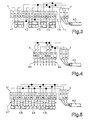
- Fig. 3 shows the first embodiment of the terminal arrangement of Fig. 1 for output channels.
- the voltage supply line K0 is three-pole connected to the terminal block 4 with the three terminals L, N, PE.
- the wiring between the terminal block 4 and the multi-pole terminal block 5 is done on the one hand by printed conductor tracks (solid lines), on the other hand by externally routed lines 7.N, 7.L (dash-dotted lines).
- This mixed wiring offers the possibility of switching a voltage potential independent of the voltage supply by disconnecting the external wiring 7.N, 7.L with the switching outputs assigned to the output terminals A1, A2. This would be with only channels 3 and 4 interconnected by printed conductor tracks are not possible.
- connection between the terminals assigned to each output channel and the actuators AR1, AR2, AR3, AR4 is made using standard three-wire connecting cables K1, K2, K3, K4, which can be installed quickly and safely without external support points.
- FIG. 4 shows a modified exemplary embodiment for output channels.
- two output channels I, II or III, IV are interconnected and interlocked so that two drive motors, for example for a roller shutter, can be controlled, the connection between terminal block 5 'and actuators being made via four-core connecting lines K5, K6. Again, only simple wiring work on the construction site is required.
- FIG. 5 shows an exemplary embodiment of the terminal arrangement and wiring for four input channels E1, E2, E3, E4.
- the terminals L, N, PE of the same name of the two terminal blocks 4, 5 '' are firmly connected to one another via printed conductor tracks.
- Four external sensors SR1, SR2, SR3, SR4 are connected to the corresponding terminals via four-wire connecting lines K7, K8, K9, K10. No support clamps are required here either, the wiring is done quickly and with great security.
Landscapes
- Engineering & Computer Science (AREA)
- Microelectronics & Electronic Packaging (AREA)
- Architecture (AREA)
- Civil Engineering (AREA)
- Structural Engineering (AREA)
- Heterocyclic Carbon Compounds Containing A Hetero Ring Having Oxygen Or Sulfur (AREA)
- Nitrogen And Oxygen Or Sulfur-Condensed Heterocyclic Ring Systems (AREA)
- Pharmaceuticals Containing Other Organic And Inorganic Compounds (AREA)
- Programmable Controllers (AREA)
- Connections Arranged To Contact A Plurality Of Conductors (AREA)
- Testing, Inspecting, Measuring Of Stereoscopic Televisions And Televisions (AREA)
- Memory System Of A Hierarchy Structure (AREA)
- Test And Diagnosis Of Digital Computers (AREA)
- Testing Of Short-Circuits, Discontinuities, Leakage, Or Incorrect Line Connections (AREA)
- Selective Calling Equipment (AREA)
- Tests Of Electronic Circuits (AREA)
Applications Claiming Priority (2)
| Application Number | Priority Date | Filing Date | Title |
|---|---|---|---|
| DE4311883A DE4311883A1 (de) | 1993-04-10 | 1993-04-10 | EIB-Modul |
| DE4311883 | 1993-04-10 |
Publications (2)
| Publication Number | Publication Date |
|---|---|
| EP0620628A1 EP0620628A1 (de) | 1994-10-19 |
| EP0620628B1 true EP0620628B1 (de) | 1996-09-18 |
Family
ID=6485265
Family Applications (2)
| Application Number | Title | Priority Date | Filing Date |
|---|---|---|---|
| EP94105284A Expired - Lifetime EP0620628B1 (de) | 1993-04-10 | 1994-04-05 | EIB-Modul |
| EP94105283A Expired - Lifetime EP0620525B1 (de) | 1993-04-10 | 1994-04-05 | EIB-Modul |
Family Applications After (1)
| Application Number | Title | Priority Date | Filing Date |
|---|---|---|---|
| EP94105283A Expired - Lifetime EP0620525B1 (de) | 1993-04-10 | 1994-04-05 | EIB-Modul |
Country Status (7)
| Country | Link |
|---|---|
| EP (2) | EP0620628B1 (OSRAM) |
| AT (2) | ATE158881T1 (OSRAM) |
| DE (3) | DE4311883A1 (OSRAM) |
| DK (2) | DK0620628T3 (OSRAM) |
| ES (2) | ES2109536T3 (OSRAM) |
| FI (2) | FI110147B (OSRAM) |
| NO (2) | NO941254L (OSRAM) |
Families Citing this family (5)
| Publication number | Priority date | Publication date | Assignee | Title |
|---|---|---|---|---|
| DE19546831A1 (de) * | 1995-12-15 | 1996-06-05 | Janke Peter Dipl Inform Fh | Verfahren zum Managen von Installationen in Gebäuden |
| AT405998B (de) * | 1997-01-21 | 2000-01-25 | Felten & Guilleaume Ag Oester | Eib-gerät zum einbau in eine installationsdose |
| DE19750548B4 (de) * | 1997-11-14 | 2008-01-17 | Ts Thermo Systeme Gmbh | Elektrische Widerstandsheizung für Innenräume mit Datenbus |
| DE29802942U1 (de) * | 1998-02-19 | 1998-05-14 | Siemens AG, 80333 München | Installationseinrichtung |
| DE102007026169A1 (de) * | 2007-06-04 | 2008-12-11 | Moeller Gmbh | Vorrichtung und Verfahren zum Erkennen der Ansteuerungsart für ein spannungs- oder stromauslösendes Schaltgerät |
Family Cites Families (9)
| Publication number | Priority date | Publication date | Assignee | Title |
|---|---|---|---|---|
| DE2516404C2 (de) * | 1975-04-15 | 1986-01-23 | Tehalit Kunststoffwerk Gmbh, 6751 Heltersberg | Kabelführungskanalsystem |
| FR2308106A1 (fr) * | 1975-04-16 | 1976-11-12 | Cit Alcatel | Procede et appareil pour controler l'appariement de fils conducteurs |
| DE2746869B2 (de) * | 1977-10-19 | 1979-11-29 | Praezisa Industrieelektronik Gmbh, 4300 Essen | Funktionsprüfeinrichtung für Einzelbatterie-Notleuchten |
| US4272725A (en) * | 1979-05-03 | 1981-06-09 | Electronics Corporation Of America | Interface circuit for use with electronic control devices |
| JPS60105057A (ja) * | 1983-11-11 | 1985-06-10 | Fujitsu Ltd | 試験方式 |
| JPS6388771A (ja) * | 1986-10-02 | 1988-04-19 | オムロン株式会社 | 入出力リレー用ターミナル |
| FR2652686B1 (fr) * | 1989-10-03 | 1992-10-16 | Arnaud Alain | Tableau de depart electronique. |
| NL9101631A (nl) * | 1991-09-26 | 1993-04-16 | Holec Syst & Componenten | Verdeelinrichting. |
| DE9203064U1 (de) * | 1992-03-09 | 1992-04-30 | Tehalit GmbH, 6751 Heltersberg | Montageelement für Elektroinstallationskanäle |
-
1993
- 1993-04-10 DE DE4311883A patent/DE4311883A1/de not_active Withdrawn
-
1994
- 1994-04-05 DE DE59400659T patent/DE59400659D1/de not_active Expired - Fee Related
- 1994-04-05 DE DE59404188T patent/DE59404188D1/de not_active Expired - Fee Related
- 1994-04-05 DK DK94105284.7T patent/DK0620628T3/da active
- 1994-04-05 ES ES94105283T patent/ES2109536T3/es not_active Expired - Lifetime
- 1994-04-05 ES ES94105284T patent/ES2093467T3/es not_active Expired - Lifetime
- 1994-04-05 EP EP94105284A patent/EP0620628B1/de not_active Expired - Lifetime
- 1994-04-05 EP EP94105283A patent/EP0620525B1/de not_active Expired - Lifetime
- 1994-04-05 AT AT94105283T patent/ATE158881T1/de active
- 1994-04-05 AT AT94105284T patent/ATE143186T1/de not_active IP Right Cessation
- 1994-04-05 DK DK94105283.9T patent/DK0620525T3/da active
- 1994-04-07 NO NO941254A patent/NO941254L/no not_active Application Discontinuation
- 1994-04-07 NO NO941253A patent/NO310006B1/no not_active IP Right Cessation
- 1994-04-08 FI FI941634A patent/FI110147B/fi not_active IP Right Cessation
- 1994-04-08 FI FI941633A patent/FI941633L/fi unknown
Also Published As
| Publication number | Publication date |
|---|---|
| DK0620525T3 (da) | 1998-05-11 |
| FI941634L (fi) | 1994-10-11 |
| HK1005763A1 (en) | 1999-01-22 |
| FI941633A0 (fi) | 1994-04-08 |
| ES2109536T3 (es) | 1998-01-16 |
| EP0620525B1 (de) | 1997-10-01 |
| NO941253D0 (no) | 1994-04-07 |
| FI110147B (fi) | 2002-11-29 |
| NO941253L (no) | 1994-10-11 |
| NO941254D0 (no) | 1994-04-07 |
| ATE143186T1 (de) | 1996-10-15 |
| NO310006B1 (no) | 2001-04-30 |
| NO941254L (no) | 1994-10-11 |
| DE59400659D1 (de) | 1996-10-24 |
| ATE158881T1 (de) | 1997-10-15 |
| EP0620628A1 (de) | 1994-10-19 |
| DE59404188D1 (de) | 1997-11-06 |
| FI941634A0 (fi) | 1994-04-08 |
| DE4311883A1 (de) | 1994-10-13 |
| ES2093467T3 (es) | 1996-12-16 |
| EP0620525A1 (de) | 1994-10-19 |
| DK0620628T3 (OSRAM) | 1997-03-17 |
| FI941633A7 (fi) | 1994-10-11 |
| FI941633L (fi) | 1994-10-11 |
Similar Documents
| Publication | Publication Date | Title |
|---|---|---|
| EP0436804B1 (de) | Elektrische Installationseinheit für die Hausleittechnik | |
| EP0772132B1 (de) | Aktor/Sensor-Kombination für die Gebäudesystemtechnik | |
| EP0452658B1 (de) | Anschlusseinrichtung für die Hausleittechnik | |
| DE19605698C1 (de) | Anschlußeinrichtung für ein elektrisches Installationssystem | |
| EP1258957B1 (de) | Schaltgerätesystem | |
| EP0620628B1 (de) | EIB-Modul | |
| DE19714868A1 (de) | Busfähige elektrische Koppeleinheit | |
| DE202019105275U1 (de) | Funktionsmodul | |
| DE69110755T2 (de) | Elektrische Verteilungsanlage mit Aufnahmeeinrichtungen für Leitungen und elektrische Geräte. | |
| DE4225326C2 (de) | Anschlußvorrichtung | |
| EP1798899B1 (de) | Unterputz-Verteilerdose für Niederspannungs-Stromnetze | |
| DE20203911U1 (de) | Kontaktfeld, Messanordnung mit einem Kontaktfeld und Anschluss-, Trenn- oder Zusatzmodul der Telekommunikationstechnik mit einem Kontaktfeld oder einer Messanordnung | |
| DE19840596C1 (de) | Ventilanordnung mit mindestens einer aus mehreren elektrisch betätigbaren Ventilen bestehenden Ventileinheit | |
| EP2146401B2 (de) | Flexibler Mehrkanal-Kabelübergang | |
| DE102017011373A1 (de) | Mess- und Steuerelektronik für Niederspannungsschaltanlagen | |
| DE29917323U1 (de) | Steckdose | |
| EP2043118B1 (de) | Elektrisches/elektronisches Installationsgerät | |
| EP4071933B1 (de) | Modulare multifunktionssteckdose | |
| DE19832909A1 (de) | Installationsverteiler | |
| DE29618489U1 (de) | Vorrichtung zur Umsetzung und/oder Übertragung von optischen und/oder elektrischen Signalen | |
| EP3827483B1 (de) | Verteilervorrichtung und system zum führen und verteilen von elektrischer energie und zum bereitstellen einer datenleitenden kommunikationsverbindung | |
| EP0442046B1 (de) | Anschlusseinheit für die Hausleittechnik | |
| EP2351176A2 (de) | Elektrisches installationsgerät | |
| DE29724594U1 (de) | Anschlusseinrichtung für ein elektrisches Installationssystem | |
| DE202025101617U1 (de) | Erweiterungsmodul für einen Zähleranschlussplatz für elektronische Haushaltszähler |
Legal Events
| Date | Code | Title | Description |
|---|---|---|---|
| PUAI | Public reference made under article 153(3) epc to a published international application that has entered the european phase |
Free format text: ORIGINAL CODE: 0009012 |
|
| AK | Designated contracting states |
Kind code of ref document: A1 Designated state(s): AT BE CH DE DK ES FR GB IT LI NL SE |
|
| 17P | Request for examination filed |
Effective date: 19941012 |
|
| GRAG | Despatch of communication of intention to grant |
Free format text: ORIGINAL CODE: EPIDOS AGRA |
|
| 17Q | First examination report despatched |
Effective date: 19960109 |
|
| GRAH | Despatch of communication of intention to grant a patent |
Free format text: ORIGINAL CODE: EPIDOS IGRA |
|
| GRAA | (expected) grant |
Free format text: ORIGINAL CODE: 0009210 |
|
| GRAH | Despatch of communication of intention to grant a patent |
Free format text: ORIGINAL CODE: EPIDOS IGRA |
|
| AK | Designated contracting states |
Kind code of ref document: B1 Designated state(s): AT BE CH DE DK ES FR GB IT LI NL SE |
|
| REF | Corresponds to: |
Ref document number: 143186 Country of ref document: AT Date of ref document: 19961015 Kind code of ref document: T |
|
| REF | Corresponds to: |
Ref document number: 59400659 Country of ref document: DE Date of ref document: 19961024 |
|
| REG | Reference to a national code |
Ref country code: CH Ref legal event code: NV Representative=s name: PATENTANWAELTE SCHAAD, BALASS, MENZL & PARTNER AG |
|
| ET | Fr: translation filed | ||
| ITF | It: translation for a ep patent filed | ||
| REG | Reference to a national code |
Ref country code: ES Ref legal event code: FG2A Ref document number: 2093467 Country of ref document: ES Kind code of ref document: T3 |
|
| GBT | Gb: translation of ep patent filed (gb section 77(6)(a)/1977) |
Effective date: 19961217 |
|
| REG | Reference to a national code |
Ref country code: DK Ref legal event code: T3 |
|
| PLBE | No opposition filed within time limit |
Free format text: ORIGINAL CODE: 0009261 |
|
| STAA | Information on the status of an ep patent application or granted ep patent |
Free format text: STATUS: NO OPPOSITION FILED WITHIN TIME LIMIT |
|
| 26N | No opposition filed | ||
| REG | Reference to a national code |
Ref country code: GB Ref legal event code: IF02 |
|
| PGFP | Annual fee paid to national office [announced via postgrant information from national office to epo] |
Ref country code: GB Payment date: 20030312 Year of fee payment: 10 |
|
| PGFP | Annual fee paid to national office [announced via postgrant information from national office to epo] |
Ref country code: DE Payment date: 20030328 Year of fee payment: 10 |
|
| PGFP | Annual fee paid to national office [announced via postgrant information from national office to epo] |
Ref country code: NL Payment date: 20030416 Year of fee payment: 10 |
|
| PGFP | Annual fee paid to national office [announced via postgrant information from national office to epo] |
Ref country code: FR Payment date: 20030417 Year of fee payment: 10 |
|
| PGFP | Annual fee paid to national office [announced via postgrant information from national office to epo] |
Ref country code: ES Payment date: 20030422 Year of fee payment: 10 |
|
| PGFP | Annual fee paid to national office [announced via postgrant information from national office to epo] |
Ref country code: AT Payment date: 20030424 Year of fee payment: 10 |
|
| PGFP | Annual fee paid to national office [announced via postgrant information from national office to epo] |
Ref country code: DK Payment date: 20030425 Year of fee payment: 10 Ref country code: SE Payment date: 20030425 Year of fee payment: 10 Ref country code: CH Payment date: 20030425 Year of fee payment: 10 Ref country code: BE Payment date: 20030425 Year of fee payment: 10 |
|
| PG25 | Lapsed in a contracting state [announced via postgrant information from national office to epo] |
Ref country code: GB Free format text: LAPSE BECAUSE OF NON-PAYMENT OF DUE FEES Effective date: 20040405 Ref country code: AT Free format text: LAPSE BECAUSE OF NON-PAYMENT OF DUE FEES Effective date: 20040405 |
|
| PG25 | Lapsed in a contracting state [announced via postgrant information from national office to epo] |
Ref country code: SE Free format text: LAPSE BECAUSE OF NON-PAYMENT OF DUE FEES Effective date: 20040406 Ref country code: ES Free format text: LAPSE BECAUSE OF NON-PAYMENT OF DUE FEES Effective date: 20040406 |
|
| PG25 | Lapsed in a contracting state [announced via postgrant information from national office to epo] |
Ref country code: LI Free format text: LAPSE BECAUSE OF NON-PAYMENT OF DUE FEES Effective date: 20040430 Ref country code: DK Free format text: LAPSE BECAUSE OF NON-PAYMENT OF DUE FEES Effective date: 20040430 Ref country code: CH Free format text: LAPSE BECAUSE OF NON-PAYMENT OF DUE FEES Effective date: 20040430 Ref country code: BE Free format text: LAPSE BECAUSE OF NON-PAYMENT OF DUE FEES Effective date: 20040430 |
|
| BERE | Be: lapsed |
Owner name: *TEHALIT G.M.B.H. Effective date: 20040430 |
|
| PG25 | Lapsed in a contracting state [announced via postgrant information from national office to epo] |
Ref country code: NL Free format text: LAPSE BECAUSE OF NON-PAYMENT OF DUE FEES Effective date: 20041101 |
|
| PG25 | Lapsed in a contracting state [announced via postgrant information from national office to epo] |
Ref country code: DE Free format text: LAPSE BECAUSE OF NON-PAYMENT OF DUE FEES Effective date: 20041103 |
|
| GBPC | Gb: european patent ceased through non-payment of renewal fee | ||
| EUG | Se: european patent has lapsed | ||
| REG | Reference to a national code |
Ref country code: CH Ref legal event code: PL |
|
| PG25 | Lapsed in a contracting state [announced via postgrant information from national office to epo] |
Ref country code: FR Free format text: LAPSE BECAUSE OF NON-PAYMENT OF DUE FEES Effective date: 20041231 |
|
| NLV4 | Nl: lapsed or anulled due to non-payment of the annual fee |
Effective date: 20041101 |
|
| REG | Reference to a national code |
Ref country code: FR Ref legal event code: ST |
|
| PG25 | Lapsed in a contracting state [announced via postgrant information from national office to epo] |
Ref country code: IT Free format text: LAPSE BECAUSE OF NON-PAYMENT OF DUE FEES;WARNING: LAPSES OF ITALIAN PATENTS WITH EFFECTIVE DATE BEFORE 2007 MAY HAVE OCCURRED AT ANY TIME BEFORE 2007. THE CORRECT EFFECTIVE DATE MAY BE DIFFERENT FROM THE ONE RECORDED. Effective date: 20050405 |
|
| REG | Reference to a national code |
Ref country code: ES Ref legal event code: FD2A Effective date: 20040406 |