EP0620525B1 - EIB-Modul - Google Patents
EIB-Modul Download PDFInfo
- Publication number
- EP0620525B1 EP0620525B1 EP94105283A EP94105283A EP0620525B1 EP 0620525 B1 EP0620525 B1 EP 0620525B1 EP 94105283 A EP94105283 A EP 94105283A EP 94105283 A EP94105283 A EP 94105283A EP 0620525 B1 EP0620525 B1 EP 0620525B1
- Authority
- EP
- European Patent Office
- Prior art keywords
- signal
- input
- test
- output
- bus
- Prior art date
- Legal status (The legal status is an assumption and is not a legal conclusion. Google has not performed a legal analysis and makes no representation as to the accuracy of the status listed.)
- Expired - Lifetime
Links
Images

Classifications
-
- H—ELECTRICITY
- H05—ELECTRIC TECHNIQUES NOT OTHERWISE PROVIDED FOR
- H05K—PRINTED CIRCUITS; CASINGS OR CONSTRUCTIONAL DETAILS OF ELECTRIC APPARATUS; MANUFACTURE OF ASSEMBLAGES OF ELECTRICAL COMPONENTS
- H05K7/00—Constructional details common to different types of electric apparatus
- H05K7/14—Mounting supporting structure in casing or on frame or rack
- H05K7/1438—Back panels or connecting means therefor; Terminals; Coding means to avoid wrong insertion
- H05K7/1447—External wirings; Wiring ducts; Laying cables
-
- H—ELECTRICITY
- H02—GENERATION; CONVERSION OR DISTRIBUTION OF ELECTRIC POWER
- H02G—INSTALLATION OF ELECTRIC CABLES OR LINES, OR OF COMBINED OPTICAL AND ELECTRIC CABLES OR LINES
- H02G3/00—Installations of electric cables or lines or protective tubing therefor in or on buildings, equivalent structures or vehicles
-
- H—ELECTRICITY
- H01—ELECTRIC ELEMENTS
- H01H—ELECTRIC SWITCHES; RELAYS; SELECTORS; EMERGENCY PROTECTIVE DEVICES
- H01H2300/00—Orthogonal indexing scheme relating to electric switches, relays, selectors or emergency protective devices covered by H01H
- H01H2300/03—Application domotique, e.g. for house automation, bus connected switches, sensors, loads or intelligent wiring
-
- H—ELECTRICITY
- H04—ELECTRIC COMMUNICATION TECHNIQUE
- H04L—TRANSMISSION OF DIGITAL INFORMATION, e.g. TELEGRAPHIC COMMUNICATION
- H04L12/00—Data switching networks
- H04L12/28—Data switching networks characterised by path configuration, e.g. LAN [Local Area Networks] or WAN [Wide Area Networks]
- H04L12/40—Bus networks
- H04L2012/40208—Bus networks characterized by the use of a particular bus standard
-
- Y—GENERAL TAGGING OF NEW TECHNOLOGICAL DEVELOPMENTS; GENERAL TAGGING OF CROSS-SECTIONAL TECHNOLOGIES SPANNING OVER SEVERAL SECTIONS OF THE IPC; TECHNICAL SUBJECTS COVERED BY FORMER USPC CROSS-REFERENCE ART COLLECTIONS [XRACs] AND DIGESTS
- Y02—TECHNOLOGIES OR APPLICATIONS FOR MITIGATION OR ADAPTATION AGAINST CLIMATE CHANGE
- Y02B—CLIMATE CHANGE MITIGATION TECHNOLOGIES RELATED TO BUILDINGS, e.g. HOUSING, HOUSE APPLIANCES OR RELATED END-USER APPLICATIONS
- Y02B90/00—Enabling technologies or technologies with a potential or indirect contribution to GHG emissions mitigation
- Y02B90/20—Smart grids as enabling technology in buildings sector
-
- Y—GENERAL TAGGING OF NEW TECHNOLOGICAL DEVELOPMENTS; GENERAL TAGGING OF CROSS-SECTIONAL TECHNOLOGIES SPANNING OVER SEVERAL SECTIONS OF THE IPC; TECHNICAL SUBJECTS COVERED BY FORMER USPC CROSS-REFERENCE ART COLLECTIONS [XRACs] AND DIGESTS
- Y04—INFORMATION OR COMMUNICATION TECHNOLOGIES HAVING AN IMPACT ON OTHER TECHNOLOGY AREAS
- Y04S—SYSTEMS INTEGRATING TECHNOLOGIES RELATED TO POWER NETWORK OPERATION, COMMUNICATION OR INFORMATION TECHNOLOGIES FOR IMPROVING THE ELECTRICAL POWER GENERATION, TRANSMISSION, DISTRIBUTION, MANAGEMENT OR USAGE, i.e. SMART GRIDS
- Y04S20/00—Management or operation of end-user stationary applications or the last stages of power distribution; Controlling, monitoring or operating thereof
- Y04S20/14—Protecting elements, switches, relays or circuit breakers
Definitions
- the invention relates to EIB modules, consisting of a universal bus coupler and a task-specific terminal with input and / or output channels according to the preamble of claims 1 and 2 respectively.
- EIBus European Installation Bus
- EIBA European Installation Bus Association
- the EIBus consists of a two-core cable and bus-compatible installation devices for distribution board installation, for surface and flush mounting and for installation in actuators, i.e. H. Consumers such as lights, blind drives and heaters. Sensors, namely light sensors, brightness and temperature sensors, anemometers etc. and actuators communicate with each other without a control center.
- EIB electronic circuitry
- the heart of the conventional EIB installation is a centrally arranged distributor with EIB basic devices, system devices and application devices. Depending on the requirements, it is equipped with EIB modules. These EIB modules have standardized dimensions and are snapped onto the standard DIN rails (DIN EN 50022), contacting the pre-wired bus at the same time.
- the bus-compatible flush-mounted, surface-mounted and built-in devices are installed in the building wherever they have to do their job.
- every bus device consists of a universal bus coupler and a task-specific end device.
- the bus coupler is set to the end device by parameterization and can manage up to four functions. Input and output channels can be combined as desired.
- the bus coupler and end device are supplied separately; the end devices, usually pushbuttons, temperature sensors and the like, are simply plugged on.
- the installer can see whether the sensor signal from the sensor connected to its input channel or the bus signal from the EIBuse controlling its actuator is present. At the same time, he can use the button to simulate the corresponding signal. In this way, the installer can test the functionality of his high-current installation before the EIBus is programmed, and he can carry out these tests conveniently "on site", not only from the centrally located distributor, where the separate interface for his microprocessor-controlled test device is located located.
- the actuator simulation signal appears at the output as soon as the test button is pressed. If, on the other hand, it is an input channel, the sensor simulation signal appears at the output as soon as the test button is pressed on an output channel.
- the internal circuitry of the logic switch is preferably such that the signals at the one input, i. H. the bus switching signal or the sensor input signal have logical priority over the test signal.
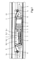
- Fig. 1 shows a plan view of an electrical installation duct 7 with the cover removed.
- An EIBus line 6 is connected to a bus coupling unit 1.
- the lower part 10 of a mounting element for the detachable fastening of installation devices is fastened to the rear wall of the duct.
- the actual EIB module consists of a universal, programmable bus coupler 1 and an associated terminal 2, here in the form of four output channels with switch contacts, each activated via a relay RL1, RL2, RL3, RL4.
- Bus coupler 1 and terminal 2 sit on a printed circuit board 3, which in turn is attached to the lower part 10 of the mounting element.
- a three-pole terminal block 4 and a multi-pole terminal block 5 are fastened on the printed circuit board 3.
- the three-pin terminal block 4 is used to connect a commercially available power supply line K0.
- Commercially available power connection lines can be connected to the multi-pole terminal block 5, only the line K4 belonging to the output channel 4 being shown for the sake of clarity.
- the poles L, N, PE of the same name of the two terminal blocks 4, 5 are wired to the circuit board 3 via printed conductor tracks.
- the output terminals A1, A2, A3, A4 are each connected to a relay-controlled switch contact. Strain reliefs 11 fix the lines K0, K4.
- a test field 13 next to bus coupler 1 shows two for the Installer very useful devices in the form of a signal diode D1, D2, D3, D4 and a test button T1, T2, T3, T4 for each of the four output channels.
- the signal diodes D1 ... D4 light up when a bus switching signal intended for the respective channel is detected. In this way, the installer can immediately see where to look for the fault in the event of a malfunction.
- the installer can also activate the associated relay RL1 ... RL4, whereupon the actuator connected to the corresponding terminal block is activated.
- This test can also be carried out if the EIBus 6 and bus coupler 1 have not yet been programmed, so that the connection wiring can be checked for functionality beforehand. Furthermore, in the event of an actuator malfunction, the installer can differentiate with certainty whether the fault responsible for the malfunction is to be found on the bus side or on the connection wiring side.
- Fig. 2 shows in the form of a block diagram the additional electronics inside the terminal 2, which is required to integrate the signal diodes D1 ... D4 and test button T1 ... T4 so that the bus connection 1 is not disturbed.
- it is an electronic switch 20, at whose one input 21 the bus control signal BS and at the other input 22 of the test signal TS, triggered when the test button T1 is pressed.
- the actuator simulation signal AS1 then appears at the output 23, which causes the relay RL1 to pick up, whereupon, for example, a 230 V AC voltage is present at the actuator terminal A1.
- the switch 20 is an OR gate, however, by the internal circuitry ensures that the bus control signal BS present at input 21 has priority over the test signal TS.
Landscapes
- Engineering & Computer Science (AREA)
- Architecture (AREA)
- Civil Engineering (AREA)
- Structural Engineering (AREA)
- Microelectronics & Electronic Packaging (AREA)
- Heterocyclic Carbon Compounds Containing A Hetero Ring Having Oxygen Or Sulfur (AREA)
- Nitrogen And Oxygen Or Sulfur-Condensed Heterocyclic Ring Systems (AREA)
- Pharmaceuticals Containing Other Organic And Inorganic Compounds (AREA)
- Programmable Controllers (AREA)
- Connections Arranged To Contact A Plurality Of Conductors (AREA)
- Memory System Of A Hierarchy Structure (AREA)
- Testing, Inspecting, Measuring Of Stereoscopic Televisions And Televisions (AREA)
- Test And Diagnosis Of Digital Computers (AREA)
- Selective Calling Equipment (AREA)
- Testing Of Short-Circuits, Discontinuities, Leakage, Or Incorrect Line Connections (AREA)
- Tests Of Electronic Circuits (AREA)
Description
- Die Erfindung betrifft EIB-Module, bestehend aus einem universellen Bus-Ankoppler und einem aufgabenspezifischen Endgerät mit Eingangs- und/oder Ausgangskanälen gemäß dem Oberbegriff der Ansprüche 1 bzw. 2.
- In der Gebäudeinstallationstechnik gewinnt der European Installation Bus (EIBus), wie er von der European Installation Bus Association (EIBA) definiert ist, zunehmend Bedeutung. Während bei der herkömmlichen Elektroinstallation jede Funktion eine eigene Leitung und jedes Steuerungssystem ein separates Netz benötigt, lassen sich mit dem EIBus alle betriebstechnischen Funktionen und Abläufe über eine gemeinsame Leitung erfassen, schalten, steuern, überwachen und melden. Die Energiezuleitung wird ohne Umwege zum Verbraucher geführt. Dabei werden Leitungen eingespart; darüber hinaus läßt sich die Gebäudeinstallation wesentlich einfacher realisieren, später problemlos erweitern und flexibel nutzen.
- Der EIBus besteht aus einer zweiadrigen Leitung und busfähigen Installationsgeräten für den Verteilereinbau, für die Aufputz- und Unterputzmontage und für den Einbau in Aktoren, d. h. Verbraucher wie Leuchten, Jalousieantriebe und Heizgeräte. Sensoren, nämlich Lichttaster, Helligkeits- und Temperaturfühler, Windmesser usw. und Aktoren kommunizieren ohne Zentrale miteinander.
- Herzstück der herkömmlichen EIB-Installation ist ein zentral angeordneter Verteiler mit EIB-Basisgeräten, Systemgeräten und Anwendungsgeräten. Er wird je nach Anforderung mit EIB-Modulen bestückt. Diese EIB-Module besitzen genormte Abmessungen und werden auf die handelsüblichen Hut-Schienen (DIN EN 50022) aufgerastet, wobei gleichzeitig der vorverdrahtete Bus kontaktiert wird.
- Die busfähigen Unterputz-, Aufputz- und Einbaugeräte werden jeweils dort im Gebäude installiert, wo sie ihre Aufgabe erfüllen müssen. Jedes Bus-Gerät besteht prinzipiell aus einem universellen Bus-Ankoppler und einem aufgabenspezifischen Endgerät. Der Bus-Ankoppler wird durch Parametrierung auf das Endgerät eingestellt und kann bis zu vier Funktionen verwalten. Eingangs- und Ausgangskanäle können beliebig kombiniert werden. Bei Unterputzgeräten werden Bus-Ankoppler und Endgerät getrennt geliefert; die Endgeräte, üblicherweise Tastschalter, Temperaturfühler und dergleichen, werden einfach aufgesteckt.
- Nachdem Verteiler, Bus-Geräte, Bus-Leitungen, Bus-Ankoppler, aufgabenspezifische Endgeräte, Energieleitungen, Aktoren und Sensoren montiert sind, muß das gesamte Installationssystem programmiert und auf einwandfreie Funktion überprüft werden. Stellt der Installateur nun fest, daß beim Druck auf einen beispielsweise als Lichtschalter vorgesehenen Sensor der zugehörige Aktor nicht funktioniert, d. h. die Glühlampe nicht leuchtet, wird er unter Verwendung seiner Testgeräte alle Hard- und Softwarefunktionen durchtesten, um schließlich festzustellen, daß nur die Glühlampe schadhaft war.
- Hier setzt nun die vorliegende Erfindung ein, die sich die Aufgabe gestellt hat, die bestehenden EIB-Module, gleichgültig ob es sich dabei um Eingänge zum Anschluß von Sensoren oder um Ausgänge zum Anschluß von Aktoren handelt, derart weiterzubilden, daß sofort und ohne jegliche Hilfsmittel getestet werden kann, ob die Fehlfunktion auf einem Fehler im Bus-System oder einem Fehler im Energie-System beruht.
- Diese Aufgabe wird gelöst durch ein EIB-Modul mit den Merkmalen des Anspruchs 1, wenn es sich um einen Ausgangskanal handelt, und durch ein EIB-Modul mit den Merkmalen des Anspruchs 2, wenn es sich um einen Eingangskanal handelt.
- Dank der Signaldiode kann der Installateur erkennen, ob das Sensorsignal des an seinen Eingangskanal angeschalteten Sensors oder das Bus-Signal des seinen Aktor steuernden EIBuses anliegen. Gleichzeitig kann er mit Hilfe des Tasters das entsprechende Signal simulieren. Auf diese Weise kann der Installateur seine starkstromseitige Installation auch schon auf Funktion testen, bevor der EIBus programmiert ist, und er kann diese Tests bequem "vor Ort" vornehmen, nicht nur vom zentral angeordneten Verteiler aus, wo sich die separate Schnittstelle für sein mikroprozessorgesteuertes Testgerät befindet.
- Dank des logischen Schalters mit zwei Eingängen und einem Ausgang erscheint am Ausgang das Aktor-Simulationssignal, sobald der Testtaster betätigt wird. Handelt es sich dagegen um einen Eingangskanal, erscheint am Ausgang das Sensor-Simulationssignal, sobald an einem Ausgangskanal der Testtaster betätigt wird.
- Vorzugsweise ist die Innenbeschaltung des logischen Schalters derart, daß die an dem einen Eingang liegenden Signale, d. h. das Bus-Schaltsignal bzw. das Sensoreingangssignal, logischen Vorrang haben vor dem Testsignal.
- Anhand der Zeichnung soll die Erfindung in Form von Ausführungsbeispielen näher erläutert werden. Es zeigen
- Fig. 1
- eine Draufsicht auf einen Elektroinstallationskanal mit eingebautem EIB-Modul,
- Fig. 2
- das Blockschaltbild eines elektronischen Schalters für einen EIB-Modul,
- Fig. 1 zeigt eine Draufsicht auf einen Elektroinstallationskanal 7 mit abgenommenem Deckel. Eine EIBus-Leitung 6 ist mit einem Busankoppler 1 verbunden. An der Kanalrückwand ist das Unterteil 10 eines Montageelements zum lösbaren Befestigen von Installationsgeräten befestigt.
- Das eigentliche EIB-Modul besteht aus einem universellen, programmierbaren Bus-Ankoppler 1 und einem zugehörigen Endgerät 2, hier in Form von vier Ausgangskanälen mit Schaltkontakten, jeweils aktiviert über ein Relais RL1, RL2, RL3, RL4. Bus-Ankoppler 1 und Endgerät 2 sitzen auf einer gedruckten Schaltungsplatine 3, die ihrerseits auf dem Unterteil 10 des Montageelements befestigt ist.
- Auf der gedruckten Schaltungsplatine 3 sind darüber hinaus ein dreipoliger Klemmenblock 4 und ein vielpoliger Klemmenblock 5 befestigt. Der dreipolige Klemmenblock 4 dient zum Anschluß einer handelsüblichen Stromversorgungsleitung K0. An den vielpoligen Klemmenblock 5 können handelsübliche Stromverbindungsleitungen angeschlossen werden, wobei der Übersichtlichkeit halber nur die zum Ausgangskanal 4 gehörende Leitung K4 zeichnerisch dargestellt ist. Die gleichnamigen Pole L, N, PE der beiden Klemmenblöcke 4, 5 sind über gedruckte Leiterbahnen auf der Platine 3 verdrahtet. Die Ausgangsklemmen A1, A2, A3, A4 sind mit je einem relaisgesteuerten Schaltkontakt verbunden. Zugentlastungen 11 fixieren die Leitungen K0, K4.
- Ein Testfeld 13 neben Bus-Ankoppler 1 zeigt zwei für den Installateur sehr nützliche Einrichtungen in Form je einer Signaldiode D1, D2, D3, D4 und je eines Testtasters T1, T2, T3, T4 für jeden der vier Ausgangskanäle. Die Signaldioden D1 ... D4 leuchten auf, wenn ein für den jeweiligen Kanal bestimmtes Bus-Schaltsignal erkannt wird. Auf diese Weise kann der Installateur sofort erkennen, wo bei einer Fehlfunktion der Fehler zu suchen ist.
- Durch Druck auf einen der Testtaster T1 ... T4 kann der Installateur darüber hinaus das zugehörige Relais RL1 ... RL4 zum Anzug bringen, worauf der an den entsprechenden Klemmenblock angeschlossene Aktor aktiviert wird. Dieser Test kann auch schon vorgenommen werden, wenn der EIBus 6 und Bus-Ankoppler 1 noch nicht programmiert sind, so daß eine Verbindungsverdrahtung schon vorab auf Funktionsfähigkeit geprüft werden kann. Des weiteren hat der Installateur so die Möglichkeit, bei einer Aktor-Fehlfunktion mit Sicherheit zu unterscheiden, ob der für die Fehlfunktion verantwortliche Fehler auf der Bus-Seite oder auf der Seite der Verbindungsverdrahtung zu suchen ist.
- Fig. 2 zeigt in Form eines Blockschaltbildes die Zusatzelektronik im Inneren des Endgerätes 2, die benötigt wird, um die Signaldioden D1 ... D4 und Testtaster T1 ... T4 so zu integrieren, daß die Bus-Ankopplung 1 nicht gestört wird. Prinzipiell handelt es sich um einen elektronischen Schalter 20, an dessen einem Eingang 21 das Bus-Steuersignal BS und an dessen anderem Eingang 22 das Testsignal TS, ausgelöst beim Druck auf den Testtaster T1, anliegen. Am Ausgang 23 erscheint dann das Aktor-Simulationssignal AS1, welches das Relais RL1 zum Anziehen bringt, worauf an der Aktorklemme A1 beispielsweise eine 230 V Wechselspannung anliegt.
- Der Schalter 20 ist ein ODER-Gatter, wobei jedoch durch die interne Verschaltung dafür gesorgt ist, daß das am Eingang 21 anliegende Bus-Steuersignal BS Vorrang hat vor dem Testsignal TS.
Claims (3)
- EIB-Modul, bestehend aus einem universellen Busankoppler (1) und einem aufgabenspezifischen Endgerät (2) mit wenigstens einem Ausgangskanal (A1, A2, A3, A4), gekennzeichnet durch folgende Merkmale:- jedem Kanal (A1 ... A4) ist eine Signaldiode (D1 ... D4) und ein Testtaster (T1 ... T4) zugeordnet,-- wobei die Signaldiode (D1 ... D4) das Schaltsignal des EIBus (6) anzeigt und der Testtaster (T1 ... T4) ein Aktor Aktor-Simulationssignal (AS1 ... AS4) auf den zugehörigen Aktor (Ar1 ... Ar4) gibt,- es ist ein logischer Schalter (20) mit zwei Eingängen (21, 22) und einem Ausgang (23) vorgesehen,-- am einen Eingang (21) liegt das Bus-Schaltsignal (BS) an,-- am anderen Eingang (22) liegt das Testsignal (TS) an,- am Ausgang (23) erscheint das Aktor-Simulationssignal (AS1).
- EIB-Modul, bestehend aus einem universellen Busankoppler (1) und einem aufgabenspezifischen Endgerät (2) mit wenigstens einem Eingangskanal gekennzeichnet durch folgende Merkmale:- jedem Kanal ist eine Signaldiode und ein Testtaster zugeordnet,-- wobei die Signaldiode das Schaltsignal eines angeschlossenen Sensors anzeigt und der Testtaster ein Sensor-Simulationssignal auf den EIBus gibt,- es ist ein logischer Schalter mit zwei Eingängen und einem Ausgang vorgesehen,-- am einen Eingang liegt das Sensoreingangssignal an,-- am anderen Eingang liegt das Testsignal an,- am Ausgang erscheint das Sensor-Simulationssignal.
- EIB-Modul nach Anspruch 1 oder 2, gekennzeichnet durch das Merkmal:- die am einen Eingang liegenden Signale haben Vorrang vor dem Testsignal.
Applications Claiming Priority (2)
| Application Number | Priority Date | Filing Date | Title |
|---|---|---|---|
| DE4311883 | 1993-04-10 | ||
| DE4311883A DE4311883A1 (de) | 1993-04-10 | 1993-04-10 | EIB-Modul |
Publications (2)
| Publication Number | Publication Date |
|---|---|
| EP0620525A1 EP0620525A1 (de) | 1994-10-19 |
| EP0620525B1 true EP0620525B1 (de) | 1997-10-01 |
Family
ID=6485265
Family Applications (2)
| Application Number | Title | Priority Date | Filing Date |
|---|---|---|---|
| EP94105283A Expired - Lifetime EP0620525B1 (de) | 1993-04-10 | 1994-04-05 | EIB-Modul |
| EP94105284A Expired - Lifetime EP0620628B1 (de) | 1993-04-10 | 1994-04-05 | EIB-Modul |
Family Applications After (1)
| Application Number | Title | Priority Date | Filing Date |
|---|---|---|---|
| EP94105284A Expired - Lifetime EP0620628B1 (de) | 1993-04-10 | 1994-04-05 | EIB-Modul |
Country Status (7)
| Country | Link |
|---|---|
| EP (2) | EP0620525B1 (de) |
| AT (2) | ATE158881T1 (de) |
| DE (3) | DE4311883A1 (de) |
| DK (2) | DK0620525T3 (de) |
| ES (2) | ES2093467T3 (de) |
| FI (2) | FI941633A7 (de) |
| NO (2) | NO941254L (de) |
Families Citing this family (5)
| Publication number | Priority date | Publication date | Assignee | Title |
|---|---|---|---|---|
| DE19546831A1 (de) * | 1995-12-15 | 1996-06-05 | Janke Peter Dipl Inform Fh | Verfahren zum Managen von Installationen in Gebäuden |
| AT405998B (de) * | 1997-01-21 | 2000-01-25 | Felten & Guilleaume Ag Oester | Eib-gerät zum einbau in eine installationsdose |
| DE19750548B4 (de) * | 1997-11-14 | 2008-01-17 | Ts Thermo Systeme Gmbh | Elektrische Widerstandsheizung für Innenräume mit Datenbus |
| DE29802942U1 (de) * | 1998-02-19 | 1998-05-14 | Siemens AG, 80333 München | Installationseinrichtung |
| DE102007026169A1 (de) * | 2007-06-04 | 2008-12-11 | Moeller Gmbh | Vorrichtung und Verfahren zum Erkennen der Ansteuerungsart für ein spannungs- oder stromauslösendes Schaltgerät |
Family Cites Families (9)
| Publication number | Priority date | Publication date | Assignee | Title |
|---|---|---|---|---|
| DE2516404C2 (de) * | 1975-04-15 | 1986-01-23 | Tehalit Kunststoffwerk Gmbh, 6751 Heltersberg | Kabelführungskanalsystem |
| FR2308106A1 (fr) * | 1975-04-16 | 1976-11-12 | Cit Alcatel | Procede et appareil pour controler l'appariement de fils conducteurs |
| DE2746869B2 (de) * | 1977-10-19 | 1979-11-29 | Praezisa Industrieelektronik Gmbh, 4300 Essen | Funktionsprüfeinrichtung für Einzelbatterie-Notleuchten |
| US4272725A (en) * | 1979-05-03 | 1981-06-09 | Electronics Corporation Of America | Interface circuit for use with electronic control devices |
| JPS60105057A (ja) * | 1983-11-11 | 1985-06-10 | Fujitsu Ltd | 試験方式 |
| JPS6388771A (ja) * | 1986-10-02 | 1988-04-19 | オムロン株式会社 | 入出力リレー用ターミナル |
| FR2652686B1 (fr) * | 1989-10-03 | 1992-10-16 | Arnaud Alain | Tableau de depart electronique. |
| NL9101631A (nl) * | 1991-09-26 | 1993-04-16 | Holec Syst & Componenten | Verdeelinrichting. |
| DE9203064U1 (de) * | 1992-03-09 | 1992-04-30 | Tehalit GmbH, 6751 Heltersberg | Montageelement für Elektroinstallationskanäle |
-
1993
- 1993-04-10 DE DE4311883A patent/DE4311883A1/de not_active Withdrawn
-
1994
- 1994-04-05 AT AT94105283T patent/ATE158881T1/de active
- 1994-04-05 ES ES94105284T patent/ES2093467T3/es not_active Expired - Lifetime
- 1994-04-05 DK DK94105283.9T patent/DK0620525T3/da active
- 1994-04-05 AT AT94105284T patent/ATE143186T1/de not_active IP Right Cessation
- 1994-04-05 EP EP94105283A patent/EP0620525B1/de not_active Expired - Lifetime
- 1994-04-05 DE DE59400659T patent/DE59400659D1/de not_active Expired - Fee Related
- 1994-04-05 EP EP94105284A patent/EP0620628B1/de not_active Expired - Lifetime
- 1994-04-05 DE DE59404188T patent/DE59404188D1/de not_active Expired - Fee Related
- 1994-04-05 DK DK94105284.7T patent/DK0620628T3/da active
- 1994-04-05 ES ES94105283T patent/ES2109536T3/es not_active Expired - Lifetime
- 1994-04-07 NO NO941254A patent/NO941254L/no not_active Application Discontinuation
- 1994-04-07 NO NO941253A patent/NO310006B1/no not_active IP Right Cessation
- 1994-04-08 FI FI941633A patent/FI941633A7/fi unknown
- 1994-04-08 FI FI941634A patent/FI110147B/fi not_active IP Right Cessation
Also Published As
| Publication number | Publication date |
|---|---|
| NO941254L (no) | 1994-10-11 |
| HK1005763A1 (en) | 1999-01-22 |
| NO941254D0 (no) | 1994-04-07 |
| FI941633L (fi) | 1994-10-11 |
| EP0620525A1 (de) | 1994-10-19 |
| DE4311883A1 (de) | 1994-10-13 |
| ES2093467T3 (es) | 1996-12-16 |
| NO941253L (no) | 1994-10-11 |
| NO310006B1 (no) | 2001-04-30 |
| ATE158881T1 (de) | 1997-10-15 |
| NO941253D0 (no) | 1994-04-07 |
| DK0620525T3 (da) | 1998-05-11 |
| ES2109536T3 (es) | 1998-01-16 |
| ATE143186T1 (de) | 1996-10-15 |
| DK0620628T3 (de) | 1997-03-17 |
| EP0620628A1 (de) | 1994-10-19 |
| EP0620628B1 (de) | 1996-09-18 |
| FI941633A7 (fi) | 1994-10-11 |
| FI941634A0 (fi) | 1994-04-08 |
| DE59404188D1 (de) | 1997-11-06 |
| FI941633A0 (fi) | 1994-04-08 |
| DE59400659D1 (de) | 1996-10-24 |
| FI110147B (fi) | 2002-11-29 |
| FI941634L (fi) | 1994-10-11 |
Similar Documents
| Publication | Publication Date | Title |
|---|---|---|
| EP0436804B1 (de) | Elektrische Installationseinheit für die Hausleittechnik | |
| EP1064759B1 (de) | Verfahren zum inbetriebnehmen eines bussystems sowie entsprechendes bussystem | |
| EP0772132B1 (de) | Aktor/Sensor-Kombination für die Gebäudesystemtechnik | |
| DE102009043455A1 (de) | Anordnung zum Installieren von Geräten der Gebäudesystemtechnik | |
| EP1258957A1 (de) | Schaltgerätesystem | |
| DE19544027C2 (de) | Bussystem, insbesondere zur elektrischen Installation | |
| EP0402654B1 (de) | Anschlussvorrichtung für den Anschluss elektrischer Verbraucher | |
| DE4311096C2 (de) | Teilnehmereinrichtung für ein Installationsbussystem | |
| EP0620525B1 (de) | EIB-Modul | |
| EP0437696B1 (de) | Fernschalt- oder fernsteuerbare Anschlussvorrichtung | |
| DE19515633A1 (de) | Elektroinstallation für ein Gebäude | |
| EP0035277A1 (de) | Sequentielles Übertragungssystem zum adressenlosen Anschliessen mehrerer Teilnehmer an eine Zentrale | |
| DE202019105275U1 (de) | Funktionsmodul | |
| EP3091549A1 (de) | Installationsgerät der haus- oder gebäudeinstallationstechnik mit erweiterter funktionalität | |
| EP1089398B1 (de) | Elektrische Steckdose | |
| DE19610381C2 (de) | Installationsbussystem für eine Stromschienenbeleuchtung | |
| EP0779640A2 (de) | Busfähiger Verstärkerbaustein für Antriebsanordnungen elektromagnetischer Schaltgeräte | |
| EP2502354A2 (de) | Elektrisches installationssystem | |
| EP3827483B1 (de) | Verteilervorrichtung und system zum führen und verteilen von elektrischer energie und zum bereitstellen einer datenleitenden kommunikationsverbindung | |
| WO2001079871A1 (de) | Verfahren und einrichtung zum prüfen von kabelbäumen | |
| DE4430441A1 (de) | Vorrichtung zur Steuerung von elektrischen Verbrauchern | |
| DE102009056213A1 (de) | Ethernet-Koppelgerät für die Gebäudeautomation | |
| DE102006036964B4 (de) | Baukastensystem für die Herstellung einer anwendungsspezifischen elektrischen Baueinheit und daraus hergestellte elektrische Baueinheit | |
| DE19546268A1 (de) | Busfähiger Verstärkerbaustein für Antriebsanordnungen elektromagnetischer Schaltgeräte | |
| EP1033905A2 (de) | Modulares Präsenzmeldersystem |
Legal Events
| Date | Code | Title | Description |
|---|---|---|---|
| PUAI | Public reference made under article 153(3) epc to a published international application that has entered the european phase |
Free format text: ORIGINAL CODE: 0009012 |
|
| AK | Designated contracting states |
Kind code of ref document: A1 Designated state(s): AT BE CH DE DK ES FR GB IT LI NL SE |
|
| 17P | Request for examination filed |
Effective date: 19941012 |
|
| 17Q | First examination report despatched |
Effective date: 19960307 |
|
| GRAG | Despatch of communication of intention to grant |
Free format text: ORIGINAL CODE: EPIDOS AGRA |
|
| GRAH | Despatch of communication of intention to grant a patent |
Free format text: ORIGINAL CODE: EPIDOS IGRA |
|
| GRAH | Despatch of communication of intention to grant a patent |
Free format text: ORIGINAL CODE: EPIDOS IGRA |
|
| GRAA | (expected) grant |
Free format text: ORIGINAL CODE: 0009210 |
|
| AK | Designated contracting states |
Kind code of ref document: B1 Designated state(s): AT BE CH DE DK ES FR GB IT LI NL SE |
|
| REF | Corresponds to: |
Ref document number: 158881 Country of ref document: AT Date of ref document: 19971015 Kind code of ref document: T |
|
| REG | Reference to a national code |
Ref country code: CH Ref legal event code: EP |
|
| REF | Corresponds to: |
Ref document number: 59404188 Country of ref document: DE Date of ref document: 19971106 |
|
| ITF | It: translation for a ep patent filed | ||
| ET | Fr: translation filed | ||
| REG | Reference to a national code |
Ref country code: CH Ref legal event code: NV Representative=s name: PATENTANWAELTE SCHAAD, BALASS, MENZL & PARTNER AG |
|
| REG | Reference to a national code |
Ref country code: ES Ref legal event code: FG2A Ref document number: 2109536 Country of ref document: ES Kind code of ref document: T3 |
|
| GBT | Gb: translation of ep patent filed (gb section 77(6)(a)/1977) |
Effective date: 19980106 |
|
| REG | Reference to a national code |
Ref country code: DK Ref legal event code: T3 |
|
| PLBE | No opposition filed within time limit |
Free format text: ORIGINAL CODE: 0009261 |
|
| STAA | Information on the status of an ep patent application or granted ep patent |
Free format text: STATUS: NO OPPOSITION FILED WITHIN TIME LIMIT |
|
| 26N | No opposition filed | ||
| PGFP | Annual fee paid to national office [announced via postgrant information from national office to epo] |
Ref country code: GB Payment date: 19990324 Year of fee payment: 6 |
|
| PGFP | Annual fee paid to national office [announced via postgrant information from national office to epo] |
Ref country code: DE Payment date: 19990406 Year of fee payment: 6 |
|
| PGFP | Annual fee paid to national office [announced via postgrant information from national office to epo] |
Ref country code: SE Payment date: 19990412 Year of fee payment: 6 |
|
| PGFP | Annual fee paid to national office [announced via postgrant information from national office to epo] |
Ref country code: FR Payment date: 19990420 Year of fee payment: 6 |
|
| PGFP | Annual fee paid to national office [announced via postgrant information from national office to epo] |
Ref country code: ES Payment date: 19990421 Year of fee payment: 6 |
|
| PGFP | Annual fee paid to national office [announced via postgrant information from national office to epo] |
Ref country code: BE Payment date: 19990422 Year of fee payment: 6 Ref country code: AT Payment date: 19990422 Year of fee payment: 6 Ref country code: NL Payment date: 19990422 Year of fee payment: 6 Ref country code: CH Payment date: 19990422 Year of fee payment: 6 |
|
| PGFP | Annual fee paid to national office [announced via postgrant information from national office to epo] |
Ref country code: DK Payment date: 19990426 Year of fee payment: 6 |
|
| PG25 | Lapsed in a contracting state [announced via postgrant information from national office to epo] |
Ref country code: GB Free format text: LAPSE BECAUSE OF NON-PAYMENT OF DUE FEES Effective date: 20000405 Ref country code: DK Free format text: LAPSE BECAUSE OF NON-PAYMENT OF DUE FEES Effective date: 20000405 Ref country code: AT Free format text: LAPSE BECAUSE OF NON-PAYMENT OF DUE FEES Effective date: 20000405 |
|
| PG25 | Lapsed in a contracting state [announced via postgrant information from national office to epo] |
Ref country code: SE Free format text: LAPSE BECAUSE OF NON-PAYMENT OF DUE FEES Effective date: 20000406 Ref country code: ES Free format text: THE PATENT HAS BEEN ANNULLED BY A DECISION OF A NATIONAL AUTHORITY Effective date: 20000406 |
|
| PG25 | Lapsed in a contracting state [announced via postgrant information from national office to epo] |
Ref country code: LI Free format text: LAPSE BECAUSE OF NON-PAYMENT OF DUE FEES Effective date: 20000430 Ref country code: CH Free format text: LAPSE BECAUSE OF NON-PAYMENT OF DUE FEES Effective date: 20000430 Ref country code: BE Free format text: LAPSE BECAUSE OF NON-PAYMENT OF DUE FEES Effective date: 20000430 |
|
| BERE | Be: lapsed |
Owner name: TEHALIT G.M.B.H. Effective date: 20000430 |
|
| PG25 | Lapsed in a contracting state [announced via postgrant information from national office to epo] |
Ref country code: NL Free format text: LAPSE BECAUSE OF NON-PAYMENT OF DUE FEES Effective date: 20001101 |
|
| GBPC | Gb: european patent ceased through non-payment of renewal fee |
Effective date: 20000405 |
|
| EUG | Se: european patent has lapsed |
Ref document number: 94105283.9 |
|
| REG | Reference to a national code |
Ref country code: CH Ref legal event code: PL |
|
| REG | Reference to a national code |
Ref country code: DK Ref legal event code: EBP |
|
| PG25 | Lapsed in a contracting state [announced via postgrant information from national office to epo] |
Ref country code: FR Free format text: LAPSE BECAUSE OF NON-PAYMENT OF DUE FEES Effective date: 20001229 |
|
| NLV4 | Nl: lapsed or anulled due to non-payment of the annual fee |
Effective date: 20001101 |
|
| PG25 | Lapsed in a contracting state [announced via postgrant information from national office to epo] |
Ref country code: DE Free format text: LAPSE BECAUSE OF NON-PAYMENT OF DUE FEES Effective date: 20010201 |
|
| REG | Reference to a national code |
Ref country code: FR Ref legal event code: ST |
|
| REG | Reference to a national code |
Ref country code: ES Ref legal event code: FD2A Effective date: 20020204 |
|
| PG25 | Lapsed in a contracting state [announced via postgrant information from national office to epo] |
Ref country code: IT Free format text: LAPSE BECAUSE OF NON-PAYMENT OF DUE FEES;WARNING: LAPSES OF ITALIAN PATENTS WITH EFFECTIVE DATE BEFORE 2007 MAY HAVE OCCURRED AT ANY TIME BEFORE 2007. THE CORRECT EFFECTIVE DATE MAY BE DIFFERENT FROM THE ONE RECORDED. Effective date: 20050405 |