EP0618724A2 - Aufzeichnungs-und Wiedergabegerät für digitale Signale - Google Patents
Aufzeichnungs-und Wiedergabegerät für digitale Signale Download PDFInfo
- Publication number
- EP0618724A2 EP0618724A2 EP94104626A EP94104626A EP0618724A2 EP 0618724 A2 EP0618724 A2 EP 0618724A2 EP 94104626 A EP94104626 A EP 94104626A EP 94104626 A EP94104626 A EP 94104626A EP 0618724 A2 EP0618724 A2 EP 0618724A2
- Authority
- EP
- European Patent Office
- Prior art keywords
- data
- recording
- digital
- reproducing apparatus
- signal
- Prior art date
- Legal status (The legal status is an assumption and is not a legal conclusion. Google has not performed a legal analysis and makes no representation as to the accuracy of the status listed.)
- Withdrawn
Links
Images


Classifications
-
- G—PHYSICS
- G11—INFORMATION STORAGE
- G11B—INFORMATION STORAGE BASED ON RELATIVE MOVEMENT BETWEEN RECORD CARRIER AND TRANSDUCER
- G11B20/00—Signal processing not specific to the method of recording or reproducing; Circuits therefor
- G11B20/10—Digital recording or reproducing
- G11B20/12—Formatting, e.g. arrangement of data block or words on the record carriers
-
- H—ELECTRICITY
- H04—ELECTRIC COMMUNICATION TECHNIQUE
- H04N—PICTORIAL COMMUNICATION, e.g. TELEVISION
- H04N5/00—Details of television systems
- H04N5/76—Television signal recording
- H04N5/91—Television signal processing therefor
- H04N5/92—Transformation of the television signal for recording, e.g. modulation, frequency changing; Inverse transformation for playback
- H04N5/926—Transformation of the television signal for recording, e.g. modulation, frequency changing; Inverse transformation for playback by pulse code modulation
- H04N5/9265—Transformation of the television signal for recording, e.g. modulation, frequency changing; Inverse transformation for playback by pulse code modulation with processing of the sound signal
- H04N5/9267—Transformation of the television signal for recording, e.g. modulation, frequency changing; Inverse transformation for playback by pulse code modulation with processing of the sound signal using time division multiplex of the PCM audio and PCM video signals
- H04N5/9268—Transformation of the television signal for recording, e.g. modulation, frequency changing; Inverse transformation for playback by pulse code modulation with processing of the sound signal using time division multiplex of the PCM audio and PCM video signals with insertion of the PCM audio signals in the vertical blanking interval of the PCM video signal
-
- G—PHYSICS
- G11—INFORMATION STORAGE
- G11B—INFORMATION STORAGE BASED ON RELATIVE MOVEMENT BETWEEN RECORD CARRIER AND TRANSDUCER
- G11B20/00—Signal processing not specific to the method of recording or reproducing; Circuits therefor
- G11B20/10—Digital recording or reproducing
- G11B20/12—Formatting, e.g. arrangement of data block or words on the record carriers
- G11B20/1201—Formatting, e.g. arrangement of data block or words on the record carriers on tapes
- G11B20/1207—Formatting, e.g. arrangement of data block or words on the record carriers on tapes with transverse tracks only
- G11B20/1208—Formatting, e.g. arrangement of data block or words on the record carriers on tapes with transverse tracks only for continuous data, e.g. digitised analog information signals, pulse code modulated [PCM] data
-
- G—PHYSICS
- G11—INFORMATION STORAGE
- G11B—INFORMATION STORAGE BASED ON RELATIVE MOVEMENT BETWEEN RECORD CARRIER AND TRANSDUCER
- G11B27/00—Editing; Indexing; Addressing; Timing or synchronising; Monitoring; Measuring tape travel
- G11B27/10—Indexing; Addressing; Timing or synchronising; Measuring tape travel
- G11B27/19—Indexing; Addressing; Timing or synchronising; Measuring tape travel by using information detectable on the record carrier
- G11B27/28—Indexing; Addressing; Timing or synchronising; Measuring tape travel by using information detectable on the record carrier by using information signals recorded by the same method as the main recording
- G11B27/30—Indexing; Addressing; Timing or synchronising; Measuring tape travel by using information detectable on the record carrier by using information signals recorded by the same method as the main recording on the same track as the main recording
- G11B27/3027—Indexing; Addressing; Timing or synchronising; Measuring tape travel by using information detectable on the record carrier by using information signals recorded by the same method as the main recording on the same track as the main recording used signal is digitally coded
- G11B27/3063—Subcodes
-
- H—ELECTRICITY
- H04—ELECTRIC COMMUNICATION TECHNIQUE
- H04N—PICTORIAL COMMUNICATION, e.g. TELEVISION
- H04N5/00—Details of television systems
- H04N5/76—Television signal recording
- H04N5/91—Television signal processing therefor
- H04N5/92—Transformation of the television signal for recording, e.g. modulation, frequency changing; Inverse transformation for playback
- H04N5/926—Transformation of the television signal for recording, e.g. modulation, frequency changing; Inverse transformation for playback by pulse code modulation
- H04N5/9261—Transformation of the television signal for recording, e.g. modulation, frequency changing; Inverse transformation for playback by pulse code modulation involving data reduction
- H04N5/9264—Transformation of the television signal for recording, e.g. modulation, frequency changing; Inverse transformation for playback by pulse code modulation involving data reduction using transform coding
-
- H—ELECTRICITY
- H04—ELECTRIC COMMUNICATION TECHNIQUE
- H04N—PICTORIAL COMMUNICATION, e.g. TELEVISION
- H04N7/00—Television systems
- H04N7/24—Systems for the transmission of television signals using pulse code modulation
- H04N7/52—Systems for transmission of a pulse code modulated video signal with one or more other pulse code modulated signals, e.g. an audio signal or a synchronizing signal
- H04N7/54—Systems for transmission of a pulse code modulated video signal with one or more other pulse code modulated signals, e.g. an audio signal or a synchronizing signal the signals being synchronous
-
- G—PHYSICS
- G11—INFORMATION STORAGE
- G11B—INFORMATION STORAGE BASED ON RELATIVE MOVEMENT BETWEEN RECORD CARRIER AND TRANSDUCER
- G11B2220/00—Record carriers by type
- G11B2220/90—Tape-like record carriers
-
- H—ELECTRICITY
- H04—ELECTRIC COMMUNICATION TECHNIQUE
- H04N—PICTORIAL COMMUNICATION, e.g. TELEVISION
- H04N5/00—Details of television systems
- H04N5/76—Television signal recording
- H04N5/78—Television signal recording using magnetic recording
- H04N5/782—Television signal recording using magnetic recording on tape
- H04N5/7824—Television signal recording using magnetic recording on tape with rotating magnetic heads
- H04N5/7826—Television signal recording using magnetic recording on tape with rotating magnetic heads involving helical scanning of the magnetic tape
- H04N5/78263—Television signal recording using magnetic recording on tape with rotating magnetic heads involving helical scanning of the magnetic tape for recording on tracks inclined relative to the direction of movement of the tape
-
- H—ELECTRICITY
- H04—ELECTRIC COMMUNICATION TECHNIQUE
- H04N—PICTORIAL COMMUNICATION, e.g. TELEVISION
- H04N5/00—Details of television systems
- H04N5/76—Television signal recording
- H04N5/78—Television signal recording using magnetic recording
- H04N5/784—Television signal recording using magnetic recording on a sheet
Definitions
- This invention relates to an apparatus for recording and reproducing a digital signal such as a digital video signal or a digital audio signal onto and from a track of a recording medium.
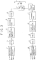
- FIG. 3 shows a construction of an exemplary one of conventional digital signal recording and reproducing apparatus of the type mentioned.
- the digital signal recording and reproducing apparatus shown includes a recording processing circuit 1 to which a brightness signal Y and a pair of color difference signals PR and PB which constitute analog component video signals are inputted.
- the signals are processed by various processes including analog to digital conversion, blocking, shuffling, DCT(discrete cosine transform), compression by quantization and variable length coding, and framing by the recording processing circuit 1, and then supplied to a parity generation circuit 3.
- the parity generation circuit 3 adds a parity of the product code construction to the data supplied thereto, and the resulted data from the parity generation circuit 3 are supplied to a SYNC and ID generation circuit 4, by which a synchronizing code and an ID are added to the data.
- the data from the SYNC and ID generation circuit 4 are processed by parallel to serial conversion and conversion into recording codes by a channel encoder 5 and are then amplified by an amplifier 6, whereafter they are supplied to a magnetic head 8 by way of a recording side terminal R of a switching circuit 7 so that they are recorded onto a magnetic tape 9.
- a digital video signal for one frame is recorded as a plurality of(for example, 10 in the NTSC system, 12 in the PAL system and 20 in the HDTV system) oblique tracks.
- a digital audio signal, a sub code signal and an ATF pilot signal are supplied to the channel encoder 5 and recorded in a time divisional relationship with the digital video signal onto each track on the magnetic tape 9 by the magnetic head 8.
- data reproduced from the magnetic tape 9 by the magnetic head 8 are supplied by way of a terminal P of the switching circuit 7 on the reproduction side to an amplifier and equalizer 10, by which amplification and correction for the frequency characteristic are performed for the data.
- the data from the amplifier and equalizer 10 are then processed by decoding into a recording code and serial to parallel conversion by a channel encoder 11 and then supplied to a SYNC and ID detection circuit 12.
- the ID detection circuit 12 thus detects a synchronizing code and an ID(identification) and supplies them together with the reproduction data to a TBC 13.
- the TBC 13 removes a time base variation from the data supplied thereto, and the resulted data from the TBC 13 are processed by error correction processing using a product code by an ECC circuit 14 and then supplied to a reproduction processing circuit 16.
- the digital video signal supplied to the reproduction processing circuit 16 is processed by various processes including deframing, variable length decoding, dequantization, inverse DCT, deshuffling and deblocking and then converted into analog component video signals by the reproduction processing circuit 16 so that the signals are outputted as a brightness signal Y and a pair of color difference signals PR and PB from the digital signal recording and reproducing apparatus.
- a digital audio signal and a sub code signal outputted from the ECC circuit 14 are processed similarly. Further, an ATF pilot signal is separated from the output of the channel decoder 11 and supplied to an ATF circuit not shown, by which tracking correction is performed.
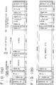
- FIG. 4 shows an example of a track format employed in the digital signal recording and reproducing apparatus constructed in such a manner as described above.
- the left end of the track shown is the head entrance(incoming) side while the right end is the head exit(outgoing) side.
- No data are recorded in any one of margins 1 and 2 and IBGs(inter block gaps) which are areas indicated by slanting lines.
- a pulse signal of a frequency, for example, equal to the bit frequency of data is recorded in a T-amble(track-amble) area added to the front of a first ATF area (ATF1) and amble areas (preamble and postamble areas) added to the opposite ends of a data recording area, and is utilized for locking of a PLL circuit for extraction of bit clocks provided on the reproduction side.
- the margin 1 and the margin 2 provided at the opposite ends of the track are provided to cope with a case wherein the position at which the track is formed is displaced by jitters. Meanwhile, the IBGs are areas for assuring margins for postrecording.
- the first ATF area (ATF 1) and the second ATF area (ATF 2) into which a pilot signal for ATF and a timing synchronizing signal for postrecording are recorded are provided adjacent the margins 1 and 2, respectively. Further, in order of the scanning direction of a head from the first ATF area, a recording area for an audio signal, a recording area for a video signal, a recording area for sub codes and the second AFT area are provided. Data such as an index and a time code for a high speed search are recorded in the sub code recording area. The numeral indicating the length of each area represents the number of bytes.
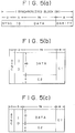
- FIGS. 5(a) to 5(c) show an example of a one synchronizing block and framing formats of a digital video signal and a digital audio signal.
- each numeral represents the number of bytes.
- FIG. 5(a) shows one synchronizing block.
- a horizontal parity of 8 bytes is added to the rear of digital video data or digital audio data of 78 bytes while a synchronizing code of 2 bytes and an ID of 3 bytes are added to the front of the digital video data or digital audio data.
- the ID has information for identification of a synchronizing block number and a type of the data. Subsequently, a method of forming such synchronizing block will be described briefly.
- FIG. 5(b) shows a framing format for a digital video signal.
- video data including quantized information and so forth
- horizontal parities C1 and vertical parities C2 are added to the data by the parity generation circuit 3.
- synchronizing codes and IDs are added to the data by the SYNC and ID generation circuit 4.
- the resulted data are converted from parallel data into serial data by the channel encoder 5 and then recorded for each synchronizing block shown in FIG. 5(a).
- Three frames in FIG. 5(b) make a digital video signal for one track.
- FIG. 5(c) shows a framing format for a digital audio signal.
- One frame shown in FIG. 5(c) makes a digital audio signal for one track.
- An ATV(Advanced Television) system wherein HDTV(high definition television) broadcasting is realized with digital transmission is investigated.
- an HDTV signal of approximately 1.2 Gbit/sec is compressed to 18 to 25 Mbit/sec by motion compensation inter-frame prediction, DCT, quantization and variable length coding, and synchronizing codes, headers and parities are added to the compressed signal.
- the resulted signal is converted into a signal of a format of a packet of a fixed length of, for example, 155 or 167 bytes to transmit the same.
- an MPEG(Moving Picture Experts Group) system As an international standard system for coding moving picture data at a high efficiency, an MPEG(Moving Picture Experts Group) system has been proposed. Also in the MPEG system, a picture signal is compressed to 5 to 10 Mbit/sec by motion compensation inter-frame prediction, DCT, quantization and variable length coding.
- a digital magnetic recording and/or reproducing apparatus which converts an input digital image signal into high efficiency codes and further into variable length codes and then records the thus obtained variable length codes, which comprises buffering means for reducing the amount of data of the variable length coding output for a predetermined period shorter than one frame period to an amount smaller than an aimed value and quantizing the image data converted into the high frequency codes with a particular quantization step, synchronizing block conversion means for converting the variable length coding output for the predetermined period into a construction of synchronizing blocks defining the data area length of the synchronizing blocks so that the variable length coding output for the predetermined period whose data amount has been controlled by the buffering means may be included in an integral number of synchronizing blocks, information addition means for adding information of the quantization step for each of the synchronizing blocks, and control means for recording an integral number of units of the image data quantized by the buffering means onto a track of a recording medium and recording or reproducing a plurality of
- a plurality of different digital signals having a same synchronizing block length such as, for example, a digital video signal and a digital audio signal are recorded and reproduced onto and from a track in a spaced relationship from each other by a distance equal to an integral number of times the synchronizing block length.
- some other digital signal such as, for example, digital data of the ATV system can be continuously recorded onto and reproduced from the areas into and from which the plurality of digital signals are to be recorded and reproduced and a gap between the areas.
- FIG. 2 there is shown a digital signal recording and reproducing apparatus according to a preferred embodiment of the present invention. It is to be noted that like elements to those of FIG. 3 are denoted by like reference numerals and overlapping description of details thereof is omitted herein to avoid redundancy.
- the digital signal recording and reproducing apparatus of the present embodiment includes, in a recording system thereof, a recording processing circuit 1, a parity generation circuit 3, a SYNC and ID generation circuit 4, a channel encoder 5 and an amplifier 6, and in a reproduction system thereof, an amplifier and equalizer 10, a channel decoder 11, a SYNC and ID detection circuit 12, a TBC 13, an ECC circuit 14 and a reproduction processing circuit 16.
- the digital signal recording and reproducing apparatus shown can record video signals supplied to the recording processing circuit 1 and an ATV signal inputted by way of an ATV codec(coder-decoder) 17 and an interface block 18.
- analog component video signals supplied to the recording processing circuit 1 are supplied to the parity generation circuit 3 by way of a switching circuit 2. Selection of a terminal of the switching circuit 2 is performed, for example, in response to an instruction inputted thereto by way of an operation panel (not shown) by a user based on data to be recorded.
- Processing by the recording processing circuit 1 and processing of the components from the parity generation circuit 3 to the amplifier 6 are basically same as the processing of the corresponding components of the digital signal recording and reproducing apparatus described hereinabove with reference to FIG. 3 except the track format of data processed.
- Also processing of data reproduced from the magnetic tape 9 upon reproduction until they are supplied to the ECC circuit 14 is basically same as that in the digital signal recording and reproducing apparatus of FIG. 3.
- Data outputted from the ECC circuit 14 are supplied to the reproduction processing circuit 16 by way of a switching circuit 15. Selection of a terminal of the switching circuit 15 may be performed in response to an instruction inputted by a user similarly as upon recording. However, it is convenient if, for example, identification data are recorded, upon recording, into a sub code area or an ATF area and are then reproduced, upon reproduction, by an identification signal detection circuit 19 so that the switching circuit 15 may be automatically changed over in response to the identification data.
- Also processing of the reproduction processing circuit 16 is basically similar to that in the digital signal recording and reproducing apparatus of FIG. 3.
- FIG. 1(a) diagrammatically shows an example of a track format of data recorded in such a manner as described above.
- the sum of amble areas and an IBG formed between a recording area for a digital audio signal and a recording area for a digital video signal and the sum of amble areas and an IBG formed between the recording area for a digital video signal and a recording area for a sub code signal both have a 182 byte length, which is set so as to be equal to twice the synchronising block length (91 bytes) for a digital video signal and a digital audio signal.
- the ATV codec 17 receives a digital video signal and a digital audio signal of the ATV system supplied thereto from a circuit not shown, separates the received digital video signal and digital audio signal into important data(PD) and ordinary data(ND), and supplies the important data(PD) and the ordinary data(ND) to the interface block 18.
- the important data here are data of low frequency components of coefficients obtained by DCT processing of video data while the ordinary data are data of high frequency components of the coefficients.
- the interface block 18 builds up the important data and the ordinary data inputted thereto from the ATV codec 17 into the data of the data formats shown in FIGS. 5(b) and 5(c) and supplies the data of the formats to the parity generation circuit 3 by way of the switching circuit 2.
- the important data and the ordinary data are built up so that the important data may be recorded at a central portion of a track. It is also possible to compare the transmission rate of the input data and the recording data of the digital signal recording and reproducing apparatus and control so that, when the recording rate is sufficiently high, the same important data may be recorded at two different locations at a central portion of a track. This prevents otherwise possible deterioration of the quality of a reproduction image upon variable speed reproduction.
- Processing of the parity generation circuit 3 and the components following it is basically same as in the case wherein analog component video signals are recorded except the track format. Also processing of data reproduced from the magnetic tape 9 upon reproduction until they are supplied to the ECC circuit 14 is basically same as in the case wherein analog component video signals are reproduced.
- Data outputted from the ECC circuit 14 are supplied to the interface block 18 by way of the switching circuit 15.
- the interface block 18 returns the thus supplied data into important data and ordinary data of an ATV signal and supplies them to the ATV codec 17.
- the ATV codec 17 converts the received important data and ordinary data back into data of the format of the original ATV signal and outputs the resulted data to the circuit not shown.
- FIG. 1(b) shows an example of a track format recorded in this manner.
- the recording capacity (182 bytes) of the IBG and amble portions can be used effectively. Further, since the capacity of the portions is equal to an integral number of times the one synchronizing block length (91 bytes), any sub code area or ATF area need not be displaced at all.
- the digital signal recording and reproducing apparatus may be constructed otherwise so as to record digital data of the MPEG system, output data of a computer or some other data.
- the sum of IBG and amble areas between a recording area for a video signal and a recording area for sub codes need not be set to an integral number of times the synchronizing block length. Furthermore, if the capacity of the recording area for sub codes in the embodiment described above is set to an integral number of times the synchronizing block length (91 bytes), then data of the ATV system or some other system can be recorded also into the recording area for sub codes.
- the one synchronizing block length may naturally be different from 91 bytes.
Applications Claiming Priority (2)
| Application Number | Priority Date | Filing Date | Title |
|---|---|---|---|
| JP95366/93 | 1993-03-30 | ||
| JP5095366A JPH06292130A (ja) | 1993-03-30 | 1993-03-30 | ディジタル信号記録再生方法及び装置 |
Publications (2)
| Publication Number | Publication Date |
|---|---|
| EP0618724A2 true EP0618724A2 (de) | 1994-10-05 |
| EP0618724A3 EP0618724A3 (de) | 1996-05-01 |
Family
ID=14135634
Family Applications (1)
| Application Number | Title | Priority Date | Filing Date |
|---|---|---|---|
| EP94104626A Withdrawn EP0618724A3 (de) | 1993-03-30 | 1994-03-23 | Aufzeichnungs-und Wiedergabegerät für digitale Signale. |
Country Status (5)
| Country | Link |
|---|---|
| US (1) | US5668677A (de) |
| EP (1) | EP0618724A3 (de) |
| JP (1) | JPH06292130A (de) |
| KR (1) | KR940022519A (de) |
| CA (1) | CA2120172A1 (de) |
Cited By (3)
| Publication number | Priority date | Publication date | Assignee | Title |
|---|---|---|---|---|
| EP0712256A2 (de) * | 1994-11-14 | 1996-05-15 | Canon Kabushiki Kaisha | Aufnahme-/Wiedergabeanlage |
| EP0732853A2 (de) * | 1995-03-16 | 1996-09-18 | Sony Corporation | Sendung und Empfang von Daten |
| US6477317B1 (en) | 1994-11-14 | 2002-11-05 | Canon Kabushiki Kaisha | Video reproducing apparatus which demultiplexes a plurality of video programs and outputs a plurality of program numbers (attribute data) in parallel |
Families Citing this family (4)
| Publication number | Priority date | Publication date | Assignee | Title |
|---|---|---|---|---|
| JP3104570B2 (ja) * | 1995-03-28 | 2000-10-30 | 日本ビクター株式会社 | ディジタル信号記録方法及び記録装置 |
| US20040260415A1 (en) * | 1999-09-08 | 2004-12-23 | Weiss Kenneth P. | Method and apparatus for achieving selected audio and other functions |
| US20090322953A1 (en) * | 1999-09-08 | 2009-12-31 | Weiss Kenneth P | Method and apparatus for achieving selected audio/video and other functions |
| JP4045940B2 (ja) * | 2002-04-05 | 2008-02-13 | ソニー株式会社 | 記録制御装置および記録制御方法、プログラム、並びに記録媒体 |
Citations (6)
| Publication number | Priority date | Publication date | Assignee | Title |
|---|---|---|---|---|
| GB2075792A (en) * | 1980-04-18 | 1981-11-18 | Sony Corp | Digitized video data recording and reproducing apparatus |
| EP0501755A2 (de) * | 1991-02-26 | 1992-09-02 | Matsushita Electric Industrial Co., Ltd. | Vorrichtung zum Aufzeichnen/Wiedergeben eines Videosignals |
| EP0553650A1 (de) * | 1992-01-14 | 1993-08-04 | Sony Corporation | Verfahren und Vorrichtung zur Übertragung von komprimierten digitalen Bildsignalen |
| JPH0646369A (ja) * | 1992-07-27 | 1994-02-18 | Hitachi Ltd | 映像信号処理装置 |
| US5289277A (en) * | 1992-11-05 | 1994-02-22 | Zenith Electronics Corp. | High definition television signal format converter |
| DE4330040A1 (de) * | 1992-09-04 | 1994-03-10 | Hitachi Ltd | Aufnahme- und/oder Wiedergabevorrichtung zum Aufnehmen und/oder Wiedergeben von Bilddaten, die gemäß unterschiedlicher Komprimierverfahren komprimiert sind |
Family Cites Families (5)
| Publication number | Priority date | Publication date | Assignee | Title |
|---|---|---|---|---|
| US5218454A (en) * | 1989-03-28 | 1993-06-08 | Canon Kabushiki Kaisha | Apparatus for improved recording of signals having video and audio components |
| DE69024350T2 (de) * | 1990-08-13 | 1996-07-18 | Matsushita Electric Ind Co Ltd | Digitale Videosignalaufnahme- und -wiedergabevorrichtung |
| JP3385623B2 (ja) * | 1992-01-29 | 2003-03-10 | ソニー株式会社 | ディジタル情報信号の伝送装置 |
| KR0135873B1 (ko) * | 1992-03-14 | 1998-05-15 | 강진구 | 디지탈 자기기록재생방법 및 장치 |
| JP3465272B2 (ja) * | 1992-08-28 | 2003-11-10 | ソニー株式会社 | デジタルデータ記録装置および記録方法 |
-
1993
- 1993-03-30 JP JP5095366A patent/JPH06292130A/ja not_active Withdrawn
-
1994
- 1994-03-23 EP EP94104626A patent/EP0618724A3/de not_active Withdrawn
- 1994-03-25 KR KR1019940006086A patent/KR940022519A/ko not_active Application Discontinuation
- 1994-03-29 CA CA002120172A patent/CA2120172A1/en not_active Abandoned
- 1994-03-30 US US08/220,172 patent/US5668677A/en not_active Expired - Fee Related
Patent Citations (6)
| Publication number | Priority date | Publication date | Assignee | Title |
|---|---|---|---|---|
| GB2075792A (en) * | 1980-04-18 | 1981-11-18 | Sony Corp | Digitized video data recording and reproducing apparatus |
| EP0501755A2 (de) * | 1991-02-26 | 1992-09-02 | Matsushita Electric Industrial Co., Ltd. | Vorrichtung zum Aufzeichnen/Wiedergeben eines Videosignals |
| EP0553650A1 (de) * | 1992-01-14 | 1993-08-04 | Sony Corporation | Verfahren und Vorrichtung zur Übertragung von komprimierten digitalen Bildsignalen |
| JPH0646369A (ja) * | 1992-07-27 | 1994-02-18 | Hitachi Ltd | 映像信号処理装置 |
| DE4330040A1 (de) * | 1992-09-04 | 1994-03-10 | Hitachi Ltd | Aufnahme- und/oder Wiedergabevorrichtung zum Aufnehmen und/oder Wiedergeben von Bilddaten, die gemäß unterschiedlicher Komprimierverfahren komprimiert sind |
| US5289277A (en) * | 1992-11-05 | 1994-02-22 | Zenith Electronics Corp. | High definition television signal format converter |
Non-Patent Citations (1)
| Title |
|---|
| PATENT ABSTRACTS OF JAPAN vol. 018 no. 275 (E-1553) ,25 May 1994 & JP-A-06 046369 (HITACHI LTD) 18 February 1994, * |
Cited By (9)
| Publication number | Priority date | Publication date | Assignee | Title |
|---|---|---|---|---|
| EP0712256A2 (de) * | 1994-11-14 | 1996-05-15 | Canon Kabushiki Kaisha | Aufnahme-/Wiedergabeanlage |
| EP0712256A3 (de) * | 1994-11-14 | 1996-07-31 | Canon Kk | Aufnahme-/Wiedergabeanlage |
| US6052507A (en) * | 1994-11-14 | 2000-04-18 | Canon Kabushiki Kaisha | Reproducing apparatus for reproducing signals from a recording medium which stores normal reproduction data and specific reproduction data |
| CN1091919C (zh) * | 1994-11-14 | 2002-10-02 | 佳能株式会社 | 译码设备及译码方法 |
| US6477317B1 (en) | 1994-11-14 | 2002-11-05 | Canon Kabushiki Kaisha | Video reproducing apparatus which demultiplexes a plurality of video programs and outputs a plurality of program numbers (attribute data) in parallel |
| CN1102321C (zh) * | 1994-11-14 | 2003-02-26 | 佳能株式会社 | 数据再生装置 |
| EP0732853A2 (de) * | 1995-03-16 | 1996-09-18 | Sony Corporation | Sendung und Empfang von Daten |
| EP0732853A3 (de) * | 1995-03-16 | 1997-07-16 | Sony Corp | Sendung und Empfang von Daten |
| US5946307A (en) * | 1995-03-16 | 1999-08-31 | Sony Corporation | System for transmitting and receiving signals of serial data interface format and serial digital data interface format on the same path |
Also Published As
| Publication number | Publication date |
|---|---|
| EP0618724A3 (de) | 1996-05-01 |
| JPH06292130A (ja) | 1994-10-18 |
| KR940022519A (ko) | 1994-10-21 |
| CA2120172A1 (en) | 1994-10-01 |
| US5668677A (en) | 1997-09-16 |
Similar Documents
| Publication | Publication Date | Title |
|---|---|---|
| EP0554086B1 (de) | Vorrichtung zum Aufzeichnen von Videoinformation | |
| EP0505985B1 (de) | Gerät zur Aufzeichnung und Wiedergabe mit hoher Kodierwirksamkeit | |
| RU2221349C2 (ru) | Устройство цифрового камкордера, применяющее сжатие видеосигнала, совместимое со стандартом экспертной группы по подвижным изображениям (эгпи-2) | |
| US5589993A (en) | Digital high definition television video recorder with trick-play features | |
| JP2954887B2 (ja) | デジタルビデオテープの記録及び再生方法 | |
| US6870884B1 (en) | High-efficiency encoder and video information recording/reproducing apparatus | |
| KR100676093B1 (ko) | 비디오 데이터 기록 장치, 비디오 데이터 기록 방법,비디오 데이터 재생 장치, 비디오 데이터 재생 방법,비디오 데이터 기록 및 재생 장치, 및 비디오 데이터 기록및 재생 방법 | |
| KR20000035332A (ko) | 데이터 기록 장치, 데이터 기록 방법, 데이터 기록 및재생 장치, 데이터 기록 및 재생 방법, 데이터 재생 장치,데이터 재생 방법, 데이터 기록 매체, 디지털 데이터 재생장치, 디지털 데이터 재생 방법, 동기 검출 장치, 및 동기검출 방법 | |
| CA2152129A1 (en) | Method and apparatus for recording digital video signals and apparatus for reproducing the digital video signals | |
| EP1298924B1 (de) | Digitaler Aufzeichnungsträger und Verfahren und Anordnung zur Steuerung der Aufzeichnung und der Wiedergabe im digitalen Aufzeichnungsträger | |
| US5377050A (en) | Digital image signal recording-reproducing apparatus and method thereof | |
| EP0599226B1 (de) | Verfahren zum Überspielen von digitalen Videosignalen | |
| US5668677A (en) | Apparatus for recording and reproducing variable length codes | |
| JPH06150568A (ja) | データ記録装置 | |
| KR100719780B1 (ko) | 데이터 전송 장치 및 방법, 기록 장치 및 기록 및 재생 장치 | |
| JP2002142192A (ja) | 信号処理装置および方法、ならびに、記録装置および方法 | |
| JPH0548995A (ja) | デイジタル磁気記録装置 | |
| US5648855A (en) | Method and apparatus for varying-speed reproduction of digital video signals | |
| KR100578258B1 (ko) | 디지털비디오신호기록/재생장치및방법 | |
| EP0772366B1 (de) | Digitales Aufzeichnungs-/Wiedergabegerät | |
| JP3167590B2 (ja) | ディジタル記録再生装置 | |
| JP4010067B2 (ja) | 同期検出装置および方法、ならびに、再生装置 | |
| JP3163834B2 (ja) | ディジタル信号記録再生方法及び装置 | |
| JP3232731B2 (ja) | デジタル情報記録再生装置 | |
| JP2000149455A (ja) | データ記録装置および記録方法、データ記録再生装置および記録再生方法、並びにデータ記録媒体 |
Legal Events
| Date | Code | Title | Description |
|---|---|---|---|
| PUAI | Public reference made under article 153(3) epc to a published international application that has entered the european phase |
Free format text: ORIGINAL CODE: 0009012 |
|
| AK | Designated contracting states |
Kind code of ref document: A2 Designated state(s): DE FR GB |
|
| PUAL | Search report despatched |
Free format text: ORIGINAL CODE: 0009013 |
|
| AK | Designated contracting states |
Kind code of ref document: A3 Designated state(s): DE FR GB |
|
| 17P | Request for examination filed |
Effective date: 19961031 |
|
| 17Q | First examination report despatched |
Effective date: 19980625 |
|
| GRAG | Despatch of communication of intention to grant |
Free format text: ORIGINAL CODE: EPIDOS AGRA |
|
| RTI1 | Title (correction) |
Free format text: DIGITAL SIGNAL RECORDING APPARATUS |
|
| RTI1 | Title (correction) |
Free format text: DIGITAL SIGNAL RECORDING APPARATUS |
|
| GRAG | Despatch of communication of intention to grant |
Free format text: ORIGINAL CODE: EPIDOS AGRA |
|
| GRAH | Despatch of communication of intention to grant a patent |
Free format text: ORIGINAL CODE: EPIDOS IGRA |
|
| STAA | Information on the status of an ep patent application or granted ep patent |
Free format text: STATUS: THE APPLICATION IS DEEMED TO BE WITHDRAWN |
|
| 18D | Application deemed to be withdrawn |
Effective date: 20020516 |