EP0618366A1 - Machine volumétrique à mouvement planétaire - Google Patents
Machine volumétrique à mouvement planétaire Download PDFInfo
- Publication number
- EP0618366A1 EP0618366A1 EP94400686A EP94400686A EP0618366A1 EP 0618366 A1 EP0618366 A1 EP 0618366A1 EP 94400686 A EP94400686 A EP 94400686A EP 94400686 A EP94400686 A EP 94400686A EP 0618366 A1 EP0618366 A1 EP 0618366A1
- Authority
- EP
- European Patent Office
- Prior art keywords
- axis
- capsule
- piston
- axes
- crown
- Prior art date
- Legal status (The legal status is an assumption and is not a legal conclusion. Google has not performed a legal analysis and makes no representation as to the accuracy of the status listed.)
- Granted
Links
Images


Classifications
-
- F—MECHANICAL ENGINEERING; LIGHTING; HEATING; WEAPONS; BLASTING
- F04—POSITIVE - DISPLACEMENT MACHINES FOR LIQUIDS; PUMPS FOR LIQUIDS OR ELASTIC FLUIDS
- F04C—ROTARY-PISTON, OR OSCILLATING-PISTON, POSITIVE-DISPLACEMENT MACHINES FOR LIQUIDS; ROTARY-PISTON, OR OSCILLATING-PISTON, POSITIVE-DISPLACEMENT PUMPS
- F04C15/00—Component parts, details or accessories of machines, pumps or pumping installations, not provided for in groups F04C2/00 - F04C14/00
- F04C15/0057—Driving elements, brakes, couplings, transmission specially adapted for machines or pumps
- F04C15/008—Prime movers
-
- F—MECHANICAL ENGINEERING; LIGHTING; HEATING; WEAPONS; BLASTING
- F04—POSITIVE - DISPLACEMENT MACHINES FOR LIQUIDS; PUMPS FOR LIQUIDS OR ELASTIC FLUIDS
- F04C—ROTARY-PISTON, OR OSCILLATING-PISTON, POSITIVE-DISPLACEMENT MACHINES FOR LIQUIDS; ROTARY-PISTON, OR OSCILLATING-PISTON, POSITIVE-DISPLACEMENT PUMPS
- F04C2/00—Rotary-piston machines or pumps
- F04C2/08—Rotary-piston machines or pumps of intermeshing-engagement type, i.e. with engagement of co-operating members similar to that of toothed gearing
- F04C2/10—Rotary-piston machines or pumps of intermeshing-engagement type, i.e. with engagement of co-operating members similar to that of toothed gearing of internal-axis type with the outer member having more teeth or tooth-equivalents, e.g. rollers, than the inner member
Definitions
- the present invention relates to a volumetric machine with planetary movement.
- Machines of this type are in fact known, for example the document DE 42 09 607 describes a volumetric machine comprising a rotor having roughly the shape of a figure eight, that is to say the shape of a Roots pump rotor, which describes a planetary movement inside a stator: the axis of the rotor describes a circle, while it also rotates in opposite directions around its axis.
- the stator has a profile having three lobes forming three chambers each equipped with an inlet and outlet valve.
- the object of the present invention is to provide a drive device for machines with planetary movement, without mechanical bearings, and therefore perfectly suitable for dry machines.
- the subject of the invention is therefore a volumetric machine with planetary movement comprising a cylindrical piston of axis ⁇ p , rotary and situated in a cylindrical capsule of axis ⁇ c , said piston having, in a plane perpendicular to its axis ⁇ p , a section having S p axes of symmetry, said capsule defining a hollow volume whose section, by a plane perpendicular to its axis ⁇ c , has S c axes of symmetry, S p and S c differing by one, the axes ⁇ p and ⁇ c parallel, being separated by a distance E, the piston and the capsule delimiting between them at least three chambers, and the capsule comprising at least one suction inlet and one discharge outlet, characterized in that it further comprises a ferromagnetic pinion of axis ⁇ p secured to the piston and comprising N p teeth, disposed inside a ferromagnetic crown of axis ⁇ c and secured
- the subject of the invention is also a volumetric machine with planetary movement comprising a cylindrical piston of axis ⁇ p , rotary and located in a cylindrical capsule of axis ⁇ c , said piston having, in a plane perpendicular to its axis ⁇ p , a section having S p axes of symmetry, said capsule defining a hollow volume whose section, by a plane perpendicular to its axis ⁇ c , has S c axes of symmetry, S p and S c differing by one, the axes ⁇ p and ⁇ c , parallel, being separated by a distance E, the piston and the capsule delimiting between them at least three chambers, and the capsule comprising at least one suction inlet and one discharge outlet, characterized in that '' it further comprises a ferromagnetic ring of axis ⁇ p , of external diameter D1, integral with the piston, disposed at the interior of a ferromagnetic crown of
- the machine comprises a magnetic axial stop composed of at least one pair of magnetized rings, linked, one to the fixed part and the other to the mobile part.
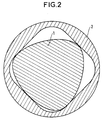
- FIGS 1, 2 and 3 show three profiles among the many possible profiles of piston and capsule according to the invention.
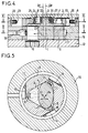
- Figure 4 shows schematically in section through a plane containing the two axes ⁇ p and ⁇ c , a machine according to the invention.
- FIG. 5 is a section on V-V in FIG. 4.
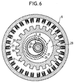
- Figure 6 is a section on VI-VI of Figure 4.
- Figure 7 is a variant, according to a view according to that of Figure 6, in which the pinion is replaced by a simple ferromagnetic ring.
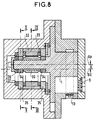
- FIG. 8 is a variant in a view corresponding to FIG. 4.
- FIG. 9 is a section along IX-IX of FIG. 8.
- Figure 10 is a section along X-X of Figure 8.
- FIGS 11, 12 and 13 show three variants of part of Figure 4.
- the machine comprises a cylindrical piston with axis ⁇ p and a cylindrical capsule with axis ⁇ c .
- the axes ⁇ p and ⁇ c are parallel and distant by a value E.
- the cylinder defining the shape of the piston has an order of symmetry with respect to its axis ⁇ p equal to S p , that of the capsule an order of symmetry equal to S c ; S p and S c are chosen so that these values differ by one.
- the geometry of the piston and of the capsule is chosen so that there is direct correspondence between these elements.
- One of the organs, capsule or piston has a P1 profile which is identified with a curve uniformly distant from a closed hypertrochoid, presenting neither double point nor cusp, excluding hypertrochoids degenerated into hypotrochoids, epitrochoids or peritrochoids.
- the P1 profile can also be at zero distance from such a hypertrochoid and therefore identify with it.
- the definition of hypertrochoids is specified in French patent 2 203 421.
- the other organ has a profile P2 which is the envelope of P1 in a relative planetary movement defined by two circles C1 and C2 of centers and respective radii (01, R1) and (02, R2), these circles C1 and C2 being respectively integral with the profiles P1 and P2 and rolling one over the other without sliding by internal contact.
- machines can be derived from machines belonging to one of the four preceding families. Indeed, one can use a profile P2 of which at least part is identified with the envelope of P1 in its movement relative to P2 and of which at least part is external to this envelope in the case of families I or II and is inside this envelope in the case of families III or IV, the different parts connecting to define a closed curve.
- Z1 1 + S 2 Ee i k S (1-S) + R m e i k S + 1-S 2 Ee i k S (1 + S) in which Z1 designates the affix of the generating point of the profile P1, each point being specified by a particular value of the kinematic parameter k whose range of variation is between O and 2S ⁇ to traverse the curve once, S is an integer which designates the order of symmetry of P1 with respect to the origin of the complex plane and is chosen arbitrarily, E and R m are two lengths chosen freely provided that the corresponding curve has neither double point nor cusp, this which indirectly limits the value of the E / R ratio m .
- Figure 1 shows, in section, by a plane perpendicular to the axes ⁇ p and ⁇ c , parallel, of the piston 1 and the capsule 2, the profile of a piston and a capsule.
- the machine shown comprises a rotor part with axis ⁇ p comprising a cylindrical piston 1, a ferromagnetic pinion 2 and a wheel 3, and a stator part with axis ⁇ c comprising a pumping cell constituting a hollow volume 4 inside of a capsule 5, a ferromagnetic ring 6 and a bearing surface 7 comprising a bore 8.
- the axes ⁇ p and ⁇ c are parallel and distant by a value E.
- the piston 1 and the capsule 2 delimit between them three chambers A, B and C which each comprise an inlet equipped with a valve, respectively 9, 10 and 11, located in a lateral flange 12 linked to the stator part, and an exhaust equipped with a valve, respectively 13, 14 and 15.
- a body 16 in the shape of a crown surrounds the capsule 5 and it has a circular recess 17 which channels the three exhausts towards a single delivery orifice 18.
- the piston 1 performs a planetary movement inside the capsule 5: the axis ⁇ p of the piston describes a circle of radius E around the axis fixes ⁇ c of the capsule while the piston turns itself around its axis ⁇ p .
- each chamber A, B and C alternately increases and decreases according to a pulsating movement.
- This planetary movement is produced by the pinion 2 and the crown 6.
- the ferromagnetic pinion 2 of axis ⁇ p which is integral with the piston 1 has N p teeth 19 and it is located inside the crown.
- ferromagnetic 6 of axis ⁇ c which is integral with the capsule 5 and which is equipped with N B electric coils 20.
- the ratio NOT p NOT B is equal to the ratio S p S vs .
- the coils 20 are supplied successively.
- the successive teeth 19 of the pinion 2 will be successively attracted by the successive coils 20 successively supplied, causing the rolling with sliding of the pinion 2 in the crown 6.
- the coils are successively supplied, that the coils can be supplied successively one by one, or else several successive coils can be simultaneously supplied and successively the next is supplied while de-energizing the first of the group supplied simultaneously.
- the rolling is done with sliding because the ratio of the radius of the pinion 2 to the radius of the crown 6 (at the end of the teeth 19 of the pinion 2 and of the poles 21 carrying the coils 20) is different from the ratio of the number N p of teeth 19 of the pinion 2 to the number N B of coils 20 of the crown 6.
- the bearing rings 22, 23 on the wheel 3 and 24, 25 on the bearing surface 7 frame an axial magnetic stop consisting of two magnetic rings, 26 carried by the wheel 3, and 27 carried by the bearing surface 7. These rings are axially magnetized and in reverse so as to attract. The rings are slightly set back from the level of the bearing rings.
- FIG. 7 shows a variant of the invention.
- This FIG. 7 is the equivalent of FIG. 6 and differs from it only by the fact that the pinion 2 is replaced by a simple ferromagnetic ring 28 without teeth.
- the diameters D1 and D2 of the ring 28 and of the crown 6 are such that D 1 D 2 is different from S p S vs , a slight clearance also existing between the crown and the ring.
- the non-slip bearing is not produced, as in the previous case, by the successive attraction of teeth to the successively supplied coils because the ratio of the number of teeth of the pinion to the number of coils of the crown was different the ratio of the rays of the pinion and the crown, but this rolling movement of the ring 28, with sliding, in the crown 6 is here simply caused by the contact of the wheel 3 in the bore 8 and on the contrary the absence of contact between the ring 28 and the crown 6. There is therefore rolling without sliding of the parts in contact: the wheel 3 in the bore 8 and the ring 28 is thus free to "roll" with sliding since there is no contact. As in the previous case, the electric coils 20 are supplied successively.
- FIGS 8, 9 and 10 show an alternative embodiment.
- the pinion 2 (or the ring 28) was reamed with a hole 29 of sufficient diameter not to come, during its movement, touching the outer periphery of the bearing 7 comprising the bore 8.
- the crown 6 and the pinion 2 (or the ring 28) on the one hand and the wheel 3 and the bearing surface 7 were coplanar as seen in FIG. 4.
- Figures 8 to 10 thus represent such a construction for a large machine where the eccentricity E between the axes ⁇ p and ⁇ c is large.
- piston 1 which comprises at the end a ferromagnetic pinion 30 comprising N p teeth 31 while the stator part is equipped with a ferromagnetic crown 32 equipped with N B coils 33.
- p NOT B S p S vs .
- the machine further carries an axial stop constituted by two magnetized rings 36 and 37 carried one, 36, by the rotor assembly and the other, 37, by the stator assembly.
- Figures 11, 12 and 13 show three variants of the embodiment of the rolling members of the wheel 3 in the bore 8 and the axial stop carried by the same elements.
- FIG. 11 there are no added bearing rings.
- the magnetic ring 26 is mounted on the wheel which is clamped between a shoulder and a cap 38.
- the magnetic ring 27 is mounted in the bearing 7 between a shoulder and a cover 39.
- FIG. 12 as in FIG. 11, there are also no added bearing rings, the bearing is made directly on the rectified surfaces of the wheel 3 and of the seat 7.
- the magnetic rings are framed by ferromagnetic rings: 40 and 41 for the wheel 3 and 42 and 43 for the seat 7. These rings are slightly recessed in relation to the rolling surfaces.
- the set of magnetic rings and ferromagnetic rings constitutes a passive magnetic reluctance stop.
- FIG. 13 there are, as in FIG. 4, bearing rings 22, 23, 24 and 25 and also, as in FIG. 12, ferromagnetic rings 40, 41, 42 and 43.
Abstract
Description
- La présente invention concerne une machine volumétrique à mouvement planétaire.
- On connaît en effet des machines de ce genre, par exemple le document DE 42 09 607 décrit une machine volumétrique comportant un rotor ayant à peu près la forme d'un huit de chiffre, c'est-à-dire la forme d'un rotor de pompe Roots, qui décrit à l'intérieur d'un stator un mouvement planétaire : l'axe du rotor décrit un cercle, tandis qu'il tourne en outre, en sens contraire, autour de son axe. Le stator a un profil présentant trois lobes formant trois chambres équipées chacune d'une soupape d'admission et de refoulement.
- Cependant, de telles machines nécessitent un mécanisme d'entraînement du mouvement planétaire avec excentrique, paliers.... et donc des mécanismes lubrifiés.
- La présente invention a pour but de proposer un dispositif d'entraînement pour des machines à mouvement planétaire, sans paliers mécaniques, et convenant donc parfaitement pour des machines sèches.
- L'invention a ainsi pour objet une machine volumétrique à mouvement planétaire comprenant un piston cylindrique d'axe Δp, rotatif et situé dans une capsule cylindrique d'axe Δc, ledit piston ayant, dans un plan perpendiculaire à son axe Δp, une section ayant Sp axes de symétrie, ladite capsule définissant un volume creux dont la section, par un plan perpendiculaire à son axe Δc, a Sc axes de symétrie, Sp et Sc se différenciant d'une unité, les axes Δp et Δc parallèles, étant séparés d'une distance E, le piston et la capsule délimitant entre eux au moins trois chambres, et la capsule comportant au moins une entrée d'aspiration et une sortie de refoulement, caractérisée en ce qu'elle comprend en outre un pignon ferromagnétique d'axe Δp solidaire du piston et comportant Np dents, disposé à l'intérieur d'une couronne ferromagnétique d'axe Δc et solidaire de la capsule, ladite couronne étant équipée de NB bobines électriques disposées radialement, en ce que le rapport


- Selon une réalisation préférée, assurant un fonctionnement sans aucun frottement, la machine comporte en outre une roue d'axe Δp solidaire du piston et de rayon R₁ = SpE, ladite roue étant disposée et roulant sans glissement dans un alésage circulaire d'axe Δc effectué dans une portée solidaire de ladite couronne, l'alésage ayant un rayon R₂ = ScE.
- Selon une autre réalisation, dans le cas où l'excentration E est importante, correspondant à des dimensions importantes du piston et de la capsule, le pignon ferromagnétique est encadré de deux bagues de roulement de rayon R₁ = SpE et la couronne ferromagnétique de deux chemins de roulement de rayon R₂ = ScE, les rayons du pignon et de la couronne étant tels qu'il existe un léger jeu entre le pignon et la couronne au niveau de la génératrice correspondant à chaque instant au contact avec roulement sans glissement desdites bagues de roulement sur lesdits chemins de roulement.
- L'invention a aussi pour objet une machine volumétrique à mouvement planétaire comprenant un piston cylindrique d'axe Δp, rotatif et situé dans une capsule cylindrique d'axe Δc, ledit piston ayant, dans un plan perpendiculaire à son axe Δp, une section ayant Sp axes de symétrie, ladite capsule définissant un volume creux dont la section, par un plan perpendiculaire à son axe Δc, a Sc axes de symétrie, Sp et Sc se différenciant d'une unité, les axes Δp et Δc, parallèles, étant séparés d'une distance E, le piston et la capsule délimitant entre eux au moins trois chambres, et la capsule comportant au moins une entrée d'aspiration et une sortie de refoulement, caractérisée en ce qu'elle comprend en outre un anneau ferromagnétique d'axe Δp, de diamètre extérieur D₁, solidaire du piston, disposé à l'intérieur d'une couronne ferromagnétique d'axe Δc, de diamètre intérieur D₂, et solidaire de la capsule, ladite couronne étant équipée d'une pluralité NB de bobines électriques disposées radialement et alimentées successivement, le rapport


- Selon une autre caractéristique, la machine comporte une butée axiale magnétique composée d'au moins une paire de bagues aimantées, liées, l'une à la partie fixe et l'autre à la partie mobile.
- L'invention va maintenant être décrite en se reportant au dessin annexé dans lequel :
- Les figures 1, 2 et 3 représentent trois profils parmi les nombreux profils possibles de piston et de capsule conformes à l'invention.
- La figure 4 montre schématiquement en coupe par un plan contenant les deux axes Δp et Δc, une machine selon l'invention.
- La figure 5 est une coupe selon V-V de la figure 4.
- La figure 6 est une coupe selon VI-VI de la figure 4.
- La figure 7 est une variante, selon une vue conforme à celle de la figure 6, dans laquelle le pignon est remplacé par un simple anneau ferromagnétique.
- La figure 8 est une variante selon une vue correspondant à la figure 4.
- La figure 9 est une coupe selon IX-IX de la figure 8.
- La figure 10 est une coupe selon X-X de la figure 8.
- Les figures 11, 12 et 13 montrent trois variantes d'une partie de la figure 4.
- Avant de décrire ces figures, d'une manière générale, la machine comprend un piston cylindrique d'axe Δp et une capsule cylindrique d'axe Δc. Les axes Δp et Δc sont parallèles et distants d'une valeur E.
- Dans cette machine, le cylindre définissant la forme du piston présente un ordre de symétrie par rapport à son axe Δp égal à Sp, celui de la capsule un ordre de symétrie égal à Sc ; Sp et Sc sont choisis de telle sorte que ces valeurs diffèrent d'une unité. En outre, la géométrie du piston et de la capsule est choisie pour qu'il y ait correspondance directe entre ces éléments.
- L'un des organes, capsule ou piston a un profil P₁ qui s'identifie à une courbe uniformément distante d'une hypertrochoïde fermée, ne présentant ni point double ni point de rebroussement, en excluant les hypertrochoïdes dégénérées en hypotrochoïdes, épitrochoïdes ou péritrochoïdes. Le profil P₁ peut également être à distance nulle d'une telle hypertrochoïde et par conséquent s'y identifier. La définition des hypertrochoïdes est précisée dans le brevet français 2 203 421. L'autre organe a un profil P₂ qui est l'enveloppe de P₁ dans un mouvement planétaire relatif défini par deux cercles C₁ et C₂ de centres et de rayons respectifs (0₁, R₁) et (0₂, R₂), ces cercles C₁ et C₂ étant respectivement solidaires des profils P₁ et P₂ et roulant l'un sur l'autre sans glissement par contact intérieur. Les centres 0₁ et 0₂ des deux cercles C₁ et C₂ sont situés sur les axes Δp et ΔC et l'excentration de ces cercles est E = |0₁0₂| correspondant à l'écartement des deux axes Δp et Δc.
- Les machines répondant à ces caractéristiques peuvent être groupées en quatre familles selon la nature de l'organe dont la forme est définie par P₁ et selon les valeurs comparatives des rayons R₁ et R₂. Il y a lieu de distinguer :
- Les machines pour lesquelles P₁ est le profil du piston et P₂ est le profil de la capsule, celui-ci s'identifiant à l'enveloppe extérieure de P₁ dans le mouvement planétaire de P₁ relativement à P₂ pour lequel R₁ = SpE et R₂ = ScE = (Sp+1)E (famille I).
- Les machines pour lesquelles P₁ est le profil du piston et P₂ est le profil de la capsule, celui-ci s'identifiant à l'enveloppe extérieure de P₁ dans le mouvement planétaire de P₁ relativement à P₂ pour lequel R₁ = SpE et R₂ = ScE = (Sp-1)E avec Sp>1 (famille II).
- Les machines pour lesquelles P₁ est le profil de la capsule et P₂ est le profil du piston, celui-ci s'identifiant à l'enveloppe intérieure de P₁ dans le mouvement planétaire de P₁ relativement à P₂ pour lequel R₂ = SpE et R₁ = ScE = (Sp-1)E avec Sp>1 (famille III).
- Les machines pour lesquelles P₁ est le profil de la capsule et P₂ est le profil du piston, celui-ci s'identifiant à l'enveloppe intérieure de P₁ dans le mouvement planétaire de P₁ relativement à P₂ pour lequel R₂ = SpE et R₁ = ScE = (Sp+1)E (famille IV).
- D'autres machines peuvent être dérivées des machines appartenant à l'une des quatre familles précédentes. En effet, on peut utiliser un profil P₂ dont une partie au moins s'identifie à l'enveloppe de P₁ dans son mouvement relatif à P₂ et dont une partie au moins est extérieure à cette enveloppe dans le cas des familles I ou II et est intérieure à cette enveloppe dans le cas des familles III ou IV, les différentes parties se raccordant pour définir une courbe fermée.
- Les profils du piston et de la capsule de ces machines présentent l'avantage de pouvoir être usinés par des machines de production en très grande série (type tournage), ce qui en diminue le prix de revient.
- Plus précisément, la description qui suit en référence aux figures énumérées ci-dessus, se rapporte à un groupe de profils de machines particulièrement intéressant, appartenant à la famille I définie ci-dessus et dont le profil P₁ du piston répond à l'équation suivante dans le plan complexe :

- L'un des intérêts de ces machines est que lorsque le profil P₁ du piston répond à l'équation ci-dessus, le profil P₂ de la capsule qui est l'enveloppe de P₁ dans le mouvement planétaire relatif, répond également à une équation du même type.
- Ainsi, la figure 1 représente, en section, par un plan perpendiculaire aux axes Δp et Δc, parallèles, du piston 1 et de la capsule 2, le profil d'un piston et d'une capsule.
- Ces profils P₁ pour le piston 1 et P₂ pour la capsule 2 répondent à l'équation ci-dessus avec un piston 1 d'ordre de symétrie Sp = 2 et une capsule 2 d'ordre de symétrie Sc = 3. E est la distance séparant les axes Δp et Δc.
- La figure 2 est une vue similaire à celle de la figure 1, mais dans le cas où le piston 1 a un ordre de symétrie Sp = 3 et la capsule 2 un ordre de symétrie Sc = 4.
- La figure 3 montre un autre exemple dans lequel le piston 1 a un ordre de symétrie Sp = 4 et la capsule 2 un ordre de symétrie Sc = 3.
- Il est à noter que le nombre d'axes de symétrie est égal à l'ordre de symétrie.
- Ces trois figures correspondent à des profils de pistons et de capsules répondant à l'équation ci-dessus.
- Dans les machines des figures suivantes, données en exemples non limitatif de l'invention, on a choisi un piston avec deux axes de symétrie Sp = 2 et une capsule avec trois axes de symétrie : Sc = 3.
- En se référant maintenant aux figures 4, 5 et 6, on va décrire une machine conforme à l'invention.
- La machine représentée comporte une partie rotorique d'axe Δp comprenant un piston cylindrique 1, un pignon ferromagnétique 2 et une roue 3, et une partie statorique d'axe Δc comportant une cellule de pompage constituant un volume creux 4 à l'intérieur d'une capsule 5, une couronne ferromagnétique 6 et une portée 7 comportant un alésage 8.
- Dans un plan perpendiculaire à son axe Δp, le piston 1 a une géométrie hypertrochoïdale dont le profil P₁ correspond à l'équation donnée ci-dessus et ayant deux axes de symétrie : Sp = 2. Il est situé dans la capsule 5 d'axe Δc qui enclôt le volume creux 4 cylindrique dont la section a également une géométrie hypertrochoïdale de profil P₂ correspondant également à l'équation ci-dessus et ayant trois axes de symétrie Sc = 3. Les axes Δp et Δc sont parallèles et distants d'une valeur E.
- Le piston 1 et la capsule 2 délimitent entre eux trois chambres A, B et C qui comportent chacune une admission équipée d'un clapet, respectivement 9, 10 et 11, située dans un flasque latéral 12 lié à la partie statorique, et un échappement équipé d'un clapet, respectivement 13, 14 et 15. Un corps 16 en forme de couronne entoure la capsule 5 et il comporte un chambrage circulaire 17 qui canalise les trois échappements vers un orifice de refoulement unique 18.
- Au cours du fonctionnement, le piston 1 effectue un mouvement planétaire à l'intérieur de la capsule 5 : l'axe Δp du piston décrit un cercle de rayon E autour de l'axe fixe Δc de la capsule pendant que le piston tourne lui-même autour de son axe Δp.
- Au cours de ce mouvement, le volume de chaque chambre A, B et C croît et décroît alternativement selon un mouvement de pulsation.
- Ce mouvement planétaire est produit par le pignon 2 et la couronne 6. A cet effet, le pignon ferromagnétique 2 d'axe Δp, qui est solidaire du piston 1 comporte Np dents 19 et il est situé à l'intérieur de la couronne ferromagnétique 6 d'axe Δc qui est solidaire de la capsule 5 et qui est équipée de NB bobines électriques 20. Le rapport


- Ainsi, par ce roulement avec glissement du pignon 2 dans la couronne 6 équipés respectivement de dents et de bobines électriques dans le rapport

- Les bagues de roulement 22, 23 sur la roue 3 et 24, 25 sur la portée 7 encadrent une butée magnétique axiale constituée de deux bagues magnétiques, 26 portée par la roue 3, et 27 portée par la portée 7. Ces bagues sont aimantées axialement et en sens inverse de façon à s'attirer. Les bagues sont légèrement en retrait par rapport au niveau des bagues de roulement.
- Dans l'exemple décrit, on a : Sp = 2 et Sc = 3 ; Np = 20 et NB = 30 et on a bien


- Pour le fonctionnement sans frottement, il existe un très léger jeu entre le pignon 2 et la couronne 6. De même il existe un très léger jeu de fonctionnement entre le piston 1 et la capsule 5, ce jeu pouvant résulter d'un rodage.
- La figure 7 montre une variante de l'invention. Cette figure 7 est l'équivalent de la figure 6 et n'en diffère que par le fait que le pignon 2 est remplacé par un simple anneau ferromagnétique 28 sans dents. Les diamètres D₁ et D₂ de l'anneau 28 et de la couronne 6 sont tels que


- Les figures 8, 9 et 10 représentent une variante de réalisation.
- Dans les figures précédentes, les cercles C₁ et C₂ de roulement sans glissement, liés respectivement au piston et à la capsule et définissant le mouvement du piston dans sa capsule, le profil P₂ de la capsule étant d'ailleurs l'enveloppe du piston dans son mouvement, produit lors du roulement sans glissement du cercle C₁ lié au piston, dans le cercle C₂, ces cercles C₁ et C₂ donc, dont les rayons sont respectivement R₁ = SpE et R₂ = ScE matérialisés par la roue 3 et l'alésage 8, étaient trop petit et ne permettaient pas de loger des bobines électriques sur la portée 7 comportant l'alésage 8. Il était donc nécessaire, pour provoquer le mouvement, de réaliser une couronne 6 de grand diamètre de façon à pouvoir y loger des bobines motrices 20, associée à un pignon 2 (ou à un anneau 28). Le pignon 2 (ou l'anneau 28) était alésé d'un trou 29 d'un diamètre suffisant pour ne pas venir, lors de son mouvement, toucher le pourtour extérieur de la portée 7 comportant l'alésage 8. En effet, la couronne 6 et le pignon 2 (ou l'anneau 28) d'une part et la roue 3 et la portée 7 étaient coplanaires comme on le voit sur la figure 4.
- Cependant, si les rayons des cercles C₁ et C₂, qui ont pour valeur, rappelons le, R₁ = SpE et R₂ = ScE, sont suffisamment grands, alors la construction peut être un peu différente : la partie motrice : couronne/pignon (anneau) peut alors correspondre aux cercles C₁ et C₂ de roulement sans glissement. En pratique on utilise des bagues et chemins de roulement dont les dimensions correspondent exactement à ces rayons R₁ et R₂ tandis qu'il existe un très léger jeu entre la couronne motrice et le pignon.
- Les figures 8 à 10 représentent ainsi une telle construction pour une machine de grande dimension où l'excentricité E entre les axes Δp et Δc est grand.
- Sur ces figures, on voit le piston 1 qui comporte en bout un pignon ferromagnétique 30 comportant Np dents 31 tandis que la partie statorique est équipée d'une couronne ferromagnétique 32 équipée de NB bobines 33. On a


- De chaque côté du pignon 30 est montée une bague de roulement 34 de rayon R₁ = SpE et de chaque côté de la couronne 32 est monté un chemin de roulement 35 de rayon R₂ = ScE. Le rayon du pignon 30 et le rayon de la couronne 32 sont tels qu'il existe un très léger jeu au niveau de la génératrice correspondant, à chaque instant, au contact avec roulement sans glissement des bagues 34 sur les chemins 35. La machine porte en outre une butée axiale constituée par deux bagues aimantées 36 et 37 portées l'une, 36, par l'ensemble rotorique et l'autre, 37, par l'ensemble statorique.
- Les figures 11, 12 et 13 montrent trois variantes de la réalisation des organes de roulement de la roue 3 dans l'alésage 8 et de la butée axiale portée par les mêmes éléments.
- Sur la figure 4, il y a des organes de roulement 22, 23, 24, 25 rapportés encadrant les bagues aimantées 26, 27 de la butée axiale.
- Sur la figure 11, il n'y a pas de bagues de roulement rapportées. La bague aimantée 26 est montée sur la roue qui est serrée entre un épaulement et un chapeau 38. De même, la bague aimantée 27 est montée dans la portée 7 entre un épaulement et un couvercle 39.
- Sur la figure 12, comme sur la figure 11, il n'y a pas non plus de bagues de roulement rapportées, le roulement se fait directement sur les surfaces rectifiées de la roue 3 et de la portée 7. Ici, les bagues aimantées sont encadrées de bagues ferromagnétiques : 40 et 41 pour la roue 3 et 42 et 43 pour la portée 7. Ces bagues sont un peu en retrait par rapport aux surfaces de roulement. L'ensemble des bagues aimantées et des bagues ferromagnétiques constitue une butée magnétique passive à réluctance.
- Enfin, sur la figure 13, il y a, comme sur la figure 4, des bagues de roulement 22, 23, 24 et 25 et aussi, comme sur la figure 12, des bagues ferromagnétiques 40, 41, 42 et 43.
Claims (6)
Applications Claiming Priority (2)
| Application Number | Priority Date | Filing Date | Title |
|---|---|---|---|
| FR9303906A FR2703406B1 (fr) | 1993-04-02 | 1993-04-02 | Machine volumétrique à mouvement planétaire. |
| FR9303906 | 1993-04-02 |
Publications (2)
| Publication Number | Publication Date |
|---|---|
| EP0618366A1 true EP0618366A1 (fr) | 1994-10-05 |
| EP0618366B1 EP0618366B1 (fr) | 1996-09-18 |
Family
ID=9445687
Family Applications (1)
| Application Number | Title | Priority Date | Filing Date |
|---|---|---|---|
| EP94400686A Expired - Lifetime EP0618366B1 (fr) | 1993-04-02 | 1994-03-30 | Machine volumétrique à mouvement planétaire |
Country Status (5)
| Country | Link |
|---|---|
| US (1) | US5370508A (fr) |
| EP (1) | EP0618366B1 (fr) |
| JP (1) | JPH06299979A (fr) |
| DE (1) | DE69400540T2 (fr) |
| FR (1) | FR2703406B1 (fr) |
Cited By (3)
| Publication number | Priority date | Publication date | Assignee | Title |
|---|---|---|---|---|
| CN102182674A (zh) * | 2011-05-18 | 2011-09-14 | 张意立 | 一种五线同步啮合弹簧补偿组合泵 |
| CN102182675A (zh) * | 2011-05-18 | 2011-09-14 | 张意立 | 一种三线同步啮合弹簧补偿组合泵 |
| CN102182678A (zh) * | 2011-06-01 | 2011-09-14 | 张意立 | 一种三线啮合内压密封新型泵 |
Families Citing this family (6)
| Publication number | Priority date | Publication date | Assignee | Title |
|---|---|---|---|---|
| US6079964A (en) * | 1998-03-10 | 2000-06-27 | Custard; John E. | Fluid handling device |
| US6247906B1 (en) * | 1999-05-28 | 2001-06-19 | Joseph M. Pijanowski | Combined pump and motor device |
| US6575719B2 (en) | 2000-07-27 | 2003-06-10 | David B. Manner | Planetary rotary machine using apertures, volutes and continuous carbon fiber reinforced peek seals |
| DE10139286A1 (de) * | 2001-08-09 | 2003-02-27 | Lev B Levitin | Rotationskolbenmaschinen (RKM-1) mit einer Abtriebswelle |
| DE10308831B3 (de) * | 2003-02-27 | 2004-09-09 | Levitin, Lev, Prof. Dr., Brookline | Rotationskolbenmaschine mit einem in einer ovalen Kammer geführten ovalen Rotationskolben |
| DE102014010745A1 (de) * | 2014-07-23 | 2016-02-11 | Rheinisch-Westfälische Technische Hochschule Aachen | Rotationskolbenpumpe |
Citations (6)
| Publication number | Priority date | Publication date | Assignee | Title |
|---|---|---|---|---|
| US2703370A (en) * | 1952-07-02 | 1955-03-01 | Steensen Sverre Johan | Electric compressor or pump motor with rolling rotor |
| US2965039A (en) * | 1957-03-31 | 1960-12-20 | Morita Yoshinori | Gear pump |
| CH556474A (de) * | 1973-05-15 | 1974-11-29 | Autoelektronik Ag | Stopfbuchslose dosierpumpe. |
| JPH02169889A (ja) * | 1988-12-20 | 1990-06-29 | Sanyo Electric Co Ltd | 回転式圧縮機 |
| DE4209607A1 (de) * | 1992-03-25 | 1992-08-13 | Rolf Eckert | Rotationskolbenmaschine als brennkraftmaschine, expansionsmaschine oder verdichter |
| US5145329A (en) * | 1990-06-29 | 1992-09-08 | Eaton Corporation | Homoplanar brushless electric gerotor |
Family Cites Families (5)
| Publication number | Priority date | Publication date | Assignee | Title |
|---|---|---|---|---|
| US2561890A (en) * | 1945-07-25 | 1951-07-24 | George C Stoddard | Dynamoelectric machine |
| US4233003A (en) * | 1978-10-10 | 1980-11-11 | Jeng Wang Shing | Rotary pump |
| US4639202A (en) * | 1985-02-06 | 1987-01-27 | Mahanay Joseph W | Gerotor device with dual valving plates |
| SU1681050A1 (ru) * | 1988-05-10 | 1991-09-30 | А.П. Величко и В.П. Величко | Роторный насос |
| FR2683000B1 (fr) * | 1991-10-23 | 1994-02-04 | Andre Leroy | Machine volumetrique a mouvement planetaire et geometrie hypertrochouidale. |
-
1993
- 1993-04-02 FR FR9303906A patent/FR2703406B1/fr not_active Expired - Fee Related
-
1994
- 1994-03-24 US US08/217,054 patent/US5370508A/en not_active Expired - Fee Related
- 1994-03-30 EP EP94400686A patent/EP0618366B1/fr not_active Expired - Lifetime
- 1994-03-30 DE DE69400540T patent/DE69400540T2/de not_active Expired - Fee Related
- 1994-04-01 JP JP6065266A patent/JPH06299979A/ja active Pending
Patent Citations (6)
| Publication number | Priority date | Publication date | Assignee | Title |
|---|---|---|---|---|
| US2703370A (en) * | 1952-07-02 | 1955-03-01 | Steensen Sverre Johan | Electric compressor or pump motor with rolling rotor |
| US2965039A (en) * | 1957-03-31 | 1960-12-20 | Morita Yoshinori | Gear pump |
| CH556474A (de) * | 1973-05-15 | 1974-11-29 | Autoelektronik Ag | Stopfbuchslose dosierpumpe. |
| JPH02169889A (ja) * | 1988-12-20 | 1990-06-29 | Sanyo Electric Co Ltd | 回転式圧縮機 |
| US5145329A (en) * | 1990-06-29 | 1992-09-08 | Eaton Corporation | Homoplanar brushless electric gerotor |
| DE4209607A1 (de) * | 1992-03-25 | 1992-08-13 | Rolf Eckert | Rotationskolbenmaschine als brennkraftmaschine, expansionsmaschine oder verdichter |
Non-Patent Citations (1)
| Title |
|---|
| PATENT ABSTRACTS OF JAPAN vol. 14, no. 432 (M - 1026) 17 September 1990 (1990-09-17) * |
Cited By (5)
| Publication number | Priority date | Publication date | Assignee | Title |
|---|---|---|---|---|
| CN102182674A (zh) * | 2011-05-18 | 2011-09-14 | 张意立 | 一种五线同步啮合弹簧补偿组合泵 |
| CN102182675A (zh) * | 2011-05-18 | 2011-09-14 | 张意立 | 一种三线同步啮合弹簧补偿组合泵 |
| CN102182675B (zh) * | 2011-05-18 | 2013-03-27 | 张意立 | 一种三线同步啮合弹簧补偿组合泵 |
| CN102182674B (zh) * | 2011-05-18 | 2013-04-10 | 张意立 | 一种五线同步啮合弹簧补偿组合泵 |
| CN102182678A (zh) * | 2011-06-01 | 2011-09-14 | 张意立 | 一种三线啮合内压密封新型泵 |
Also Published As
| Publication number | Publication date |
|---|---|
| US5370508A (en) | 1994-12-06 |
| DE69400540D1 (de) | 1996-10-24 |
| DE69400540T2 (de) | 1997-01-30 |
| FR2703406B1 (fr) | 1995-05-12 |
| EP0618366B1 (fr) | 1996-09-18 |
| FR2703406A1 (fr) | 1994-10-07 |
| JPH06299979A (ja) | 1994-10-25 |
Similar Documents
| Publication | Publication Date | Title |
|---|---|---|
| EP0618366B1 (fr) | Machine volumétrique à mouvement planétaire | |
| EP3326263A1 (fr) | Motoreducteur compact | |
| CH514787A (fr) | Machine volumétrique, notamment pompe à vide | |
| EP0539273B1 (fr) | Machine volumétrique à mouvement planétaire et géométrie hypertrochoidale | |
| FR2542835A1 (fr) | Convertisseur de couple de type axial planetaire | |
| FR2717239A1 (fr) | Dispositif de train d'engrenage à denture intérieure. | |
| EP0968381B1 (fr) | Mecanisme desmodromique | |
| EP0618365B1 (fr) | Machine volumétrique à guidage magnétique | |
| FR2522763A1 (fr) | Reducteur de vitesse | |
| EP0155497B1 (fr) | Réducteur mécanique | |
| FR2992693A1 (fr) | Pompe a engrenage interne double | |
| FR2652400A1 (fr) | Engrenage differentiel auto-freinant perfectionne. | |
| FR2992694A1 (fr) | Pompe a engrenage interieur | |
| EP0263218B1 (fr) | Mécanisme hydraulique comportant des glace et contre-glace de distribution du fluide | |
| EP2829754B1 (fr) | Bague de roulement allégée, roulement instrumenté incluant une telle bague et module motoréducteur intégrant un tel roulement | |
| FR2509802A1 (fr) | Pompes et moteurs | |
| EP3049693B1 (fr) | Dispositif réducteur de vitesse angulaire | |
| FR2706539A1 (fr) | Ensemble de deux moteurs à fluide sous pression. | |
| FR2867543A1 (fr) | Engrenage a lanterne | |
| FR2632020A1 (fr) | Dispositif tournant a engrenages pour la circulation d'un liquide | |
| EP0607069B1 (fr) | Piston de moteur hydraulique | |
| FR2657131A1 (fr) | Machine de transmission hautes performances a engrenages. | |
| EP1319837A1 (fr) | Pompe de type gerotor | |
| FR2522371A1 (fr) | Dispositif a piston spherique pour machines motrices et operatrices | |
| EP1355068A1 (fr) | Dispositif pour diviser ou réunir un débit de fluide |
Legal Events
| Date | Code | Title | Description |
|---|---|---|---|
| PUAI | Public reference made under article 153(3) epc to a published international application that has entered the european phase |
Free format text: ORIGINAL CODE: 0009012 |
|
| AK | Designated contracting states |
Kind code of ref document: A1 Designated state(s): BE CH DE FR GB IT LI LU NL |
|
| 17P | Request for examination filed |
Effective date: 19950126 |
|
| GRAG | Despatch of communication of intention to grant |
Free format text: ORIGINAL CODE: EPIDOS AGRA |
|
| GRAH | Despatch of communication of intention to grant a patent |
Free format text: ORIGINAL CODE: EPIDOS IGRA |
|
| 17Q | First examination report despatched |
Effective date: 19960301 |
|
| GRAH | Despatch of communication of intention to grant a patent |
Free format text: ORIGINAL CODE: EPIDOS IGRA |
|
| GRAA | (expected) grant |
Free format text: ORIGINAL CODE: 0009210 |
|
| AK | Designated contracting states |
Kind code of ref document: B1 Designated state(s): BE CH DE FR GB IT LI LU NL |
|
| PG25 | Lapsed in a contracting state [announced via postgrant information from national office to epo] |
Ref country code: NL Free format text: LAPSE BECAUSE OF FAILURE TO SUBMIT A TRANSLATION OF THE DESCRIPTION OR TO PAY THE FEE WITHIN THE PRESCRIBED TIME-LIMIT Effective date: 19960918 |
|
| REG | Reference to a national code |
Ref country code: CH Ref legal event code: NV Representative=s name: GEC ALSTHOM (SUISSE) S.A. DEPARTEMENT DES BREVETS |
|
| ITF | It: translation for a ep patent filed |
Owner name: JACOBACCI & PERANI S.P.A. |
|
| REF | Corresponds to: |
Ref document number: 69400540 Country of ref document: DE Date of ref document: 19961024 |
|
| GBT | Gb: translation of ep patent filed (gb section 77(6)(a)/1977) |
Effective date: 19961008 |
|
| NLV1 | Nl: lapsed or annulled due to failure to fulfill the requirements of art. 29p and 29m of the patents act | ||
| PG25 | Lapsed in a contracting state [announced via postgrant information from national office to epo] |
Ref country code: LU Free format text: LAPSE BECAUSE OF NON-PAYMENT OF DUE FEES Effective date: 19970331 Ref country code: BE Effective date: 19970331 |
|
| PLBE | No opposition filed within time limit |
Free format text: ORIGINAL CODE: 0009261 |
|
| STAA | Information on the status of an ep patent application or granted ep patent |
Free format text: STATUS: NO OPPOSITION FILED WITHIN TIME LIMIT |
|
| 26N | No opposition filed | ||
| BERE | Be: lapsed |
Owner name: ALCATEL CIT Effective date: 19970331 |
|
| PGFP | Annual fee paid to national office [announced via postgrant information from national office to epo] |
Ref country code: GB Payment date: 19980213 Year of fee payment: 5 Ref country code: FR Payment date: 19980213 Year of fee payment: 5 |
|
| PGFP | Annual fee paid to national office [announced via postgrant information from national office to epo] |
Ref country code: DE Payment date: 19980221 Year of fee payment: 5 |
|
| PGFP | Annual fee paid to national office [announced via postgrant information from national office to epo] |
Ref country code: CH Payment date: 19980225 Year of fee payment: 5 |
|
| PG25 | Lapsed in a contracting state [announced via postgrant information from national office to epo] |
Ref country code: GB Free format text: LAPSE BECAUSE OF NON-PAYMENT OF DUE FEES Effective date: 19990330 |
|
| PG25 | Lapsed in a contracting state [announced via postgrant information from national office to epo] |
Ref country code: LI Free format text: LAPSE BECAUSE OF NON-PAYMENT OF DUE FEES Effective date: 19990331 Ref country code: CH Free format text: LAPSE BECAUSE OF NON-PAYMENT OF DUE FEES Effective date: 19990331 |
|
| REG | Reference to a national code |
Ref country code: CH Ref legal event code: PL |
|
| GBPC | Gb: european patent ceased through non-payment of renewal fee |
Effective date: 19990330 |
|
| PG25 | Lapsed in a contracting state [announced via postgrant information from national office to epo] |
Ref country code: FR Free format text: LAPSE BECAUSE OF NON-PAYMENT OF DUE FEES Effective date: 19991130 |
|
| REG | Reference to a national code |
Ref country code: FR Ref legal event code: ST |
|
| PG25 | Lapsed in a contracting state [announced via postgrant information from national office to epo] |
Ref country code: DE Free format text: LAPSE BECAUSE OF NON-PAYMENT OF DUE FEES Effective date: 20000101 |
|
| PG25 | Lapsed in a contracting state [announced via postgrant information from national office to epo] |
Ref country code: IT Free format text: LAPSE BECAUSE OF NON-PAYMENT OF DUE FEES;WARNING: LAPSES OF ITALIAN PATENTS WITH EFFECTIVE DATE BEFORE 2007 MAY HAVE OCCURRED AT ANY TIME BEFORE 2007. THE CORRECT EFFECTIVE DATE MAY BE DIFFERENT FROM THE ONE RECORDED. Effective date: 20050330 |