EP0618366A1 - Verdrängermaschine mit zyklischer Bewegung - Google Patents
Verdrängermaschine mit zyklischer Bewegung Download PDFInfo
- Publication number
- EP0618366A1 EP0618366A1 EP94400686A EP94400686A EP0618366A1 EP 0618366 A1 EP0618366 A1 EP 0618366A1 EP 94400686 A EP94400686 A EP 94400686A EP 94400686 A EP94400686 A EP 94400686A EP 0618366 A1 EP0618366 A1 EP 0618366A1
- Authority
- EP
- European Patent Office
- Prior art keywords
- axis
- capsule
- piston
- crown
- axes
- Prior art date
- Legal status (The legal status is an assumption and is not a legal conclusion. Google has not performed a legal analysis and makes no representation as to the accuracy of the status listed.)
- Granted
Links
- 239000002775 capsule Substances 0.000 claims abstract description 63
- 230000005294 ferromagnetic effect Effects 0.000 claims abstract description 25
- 238000005096 rolling process Methods 0.000 claims description 22
- 230000005291 magnetic effect Effects 0.000 claims description 10
- 238000004804 winding Methods 0.000 claims 1
- 210000000056 organ Anatomy 0.000 description 3
- 238000010276 construction Methods 0.000 description 2
- 230000007246 mechanism Effects 0.000 description 2
- 230000000052 comparative effect Effects 0.000 description 1
- 230000007423 decrease Effects 0.000 description 1
- 238000009432 framing Methods 0.000 description 1
- 238000005461 lubrication Methods 0.000 description 1
- 238000004519 manufacturing process Methods 0.000 description 1
- 238000005086 pumping Methods 0.000 description 1
Images


Classifications
-
- F—MECHANICAL ENGINEERING; LIGHTING; HEATING; WEAPONS; BLASTING
- F04—POSITIVE - DISPLACEMENT MACHINES FOR LIQUIDS; PUMPS FOR LIQUIDS OR ELASTIC FLUIDS
- F04C—ROTARY-PISTON, OR OSCILLATING-PISTON, POSITIVE-DISPLACEMENT MACHINES FOR LIQUIDS; ROTARY-PISTON, OR OSCILLATING-PISTON, POSITIVE-DISPLACEMENT PUMPS
- F04C15/00—Component parts, details or accessories of machines, pumps or pumping installations, not provided for in groups F04C2/00 - F04C14/00
- F04C15/0057—Driving elements, brakes, couplings, transmission specially adapted for machines or pumps
- F04C15/008—Prime movers
-
- F—MECHANICAL ENGINEERING; LIGHTING; HEATING; WEAPONS; BLASTING
- F04—POSITIVE - DISPLACEMENT MACHINES FOR LIQUIDS; PUMPS FOR LIQUIDS OR ELASTIC FLUIDS
- F04C—ROTARY-PISTON, OR OSCILLATING-PISTON, POSITIVE-DISPLACEMENT MACHINES FOR LIQUIDS; ROTARY-PISTON, OR OSCILLATING-PISTON, POSITIVE-DISPLACEMENT PUMPS
- F04C2/00—Rotary-piston machines or pumps
- F04C2/08—Rotary-piston machines or pumps of intermeshing-engagement type, i.e. with engagement of co-operating members similar to that of toothed gearing
- F04C2/10—Rotary-piston machines or pumps of intermeshing-engagement type, i.e. with engagement of co-operating members similar to that of toothed gearing of internal-axis type with the outer member having more teeth or tooth-equivalents, e.g. rollers, than the inner member
Definitions
- the present invention relates to a volumetric machine with planetary movement.
- Machines of this type are in fact known, for example the document DE 42 09 607 describes a volumetric machine comprising a rotor having roughly the shape of a figure eight, that is to say the shape of a Roots pump rotor, which describes a planetary movement inside a stator: the axis of the rotor describes a circle, while it also rotates in opposite directions around its axis.
- the stator has a profile having three lobes forming three chambers each equipped with an inlet and outlet valve.
- the object of the present invention is to provide a drive device for machines with planetary movement, without mechanical bearings, and therefore perfectly suitable for dry machines.
- the subject of the invention is therefore a volumetric machine with planetary movement comprising a cylindrical piston of axis ⁇ p , rotary and situated in a cylindrical capsule of axis ⁇ c , said piston having, in a plane perpendicular to its axis ⁇ p , a section having S p axes of symmetry, said capsule defining a hollow volume whose section, by a plane perpendicular to its axis ⁇ c , has S c axes of symmetry, S p and S c differing by one, the axes ⁇ p and ⁇ c parallel, being separated by a distance E, the piston and the capsule delimiting between them at least three chambers, and the capsule comprising at least one suction inlet and one discharge outlet, characterized in that it further comprises a ferromagnetic pinion of axis ⁇ p secured to the piston and comprising N p teeth, disposed inside a ferromagnetic crown of axis ⁇ c and secured
- the subject of the invention is also a volumetric machine with planetary movement comprising a cylindrical piston of axis ⁇ p , rotary and located in a cylindrical capsule of axis ⁇ c , said piston having, in a plane perpendicular to its axis ⁇ p , a section having S p axes of symmetry, said capsule defining a hollow volume whose section, by a plane perpendicular to its axis ⁇ c , has S c axes of symmetry, S p and S c differing by one, the axes ⁇ p and ⁇ c , parallel, being separated by a distance E, the piston and the capsule delimiting between them at least three chambers, and the capsule comprising at least one suction inlet and one discharge outlet, characterized in that '' it further comprises a ferromagnetic ring of axis ⁇ p , of external diameter D1, integral with the piston, disposed at the interior of a ferromagnetic crown of
- the machine comprises a magnetic axial stop composed of at least one pair of magnetized rings, linked, one to the fixed part and the other to the mobile part.
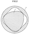
- FIGS 1, 2 and 3 show three profiles among the many possible profiles of piston and capsule according to the invention.
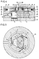
- Figure 4 shows schematically in section through a plane containing the two axes ⁇ p and ⁇ c , a machine according to the invention.
- FIG. 5 is a section on V-V in FIG. 4.
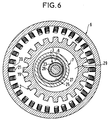
- Figure 6 is a section on VI-VI of Figure 4.
- Figure 7 is a variant, according to a view according to that of Figure 6, in which the pinion is replaced by a simple ferromagnetic ring.
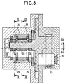
- FIG. 8 is a variant in a view corresponding to FIG. 4.
- FIG. 9 is a section along IX-IX of FIG. 8.
- Figure 10 is a section along X-X of Figure 8.
- FIGS 11, 12 and 13 show three variants of part of Figure 4.
- the machine comprises a cylindrical piston with axis ⁇ p and a cylindrical capsule with axis ⁇ c .
- the axes ⁇ p and ⁇ c are parallel and distant by a value E.
- the cylinder defining the shape of the piston has an order of symmetry with respect to its axis ⁇ p equal to S p , that of the capsule an order of symmetry equal to S c ; S p and S c are chosen so that these values differ by one.
- the geometry of the piston and of the capsule is chosen so that there is direct correspondence between these elements.
- One of the organs, capsule or piston has a P1 profile which is identified with a curve uniformly distant from a closed hypertrochoid, presenting neither double point nor cusp, excluding hypertrochoids degenerated into hypotrochoids, epitrochoids or peritrochoids.
- the P1 profile can also be at zero distance from such a hypertrochoid and therefore identify with it.
- the definition of hypertrochoids is specified in French patent 2 203 421.
- the other organ has a profile P2 which is the envelope of P1 in a relative planetary movement defined by two circles C1 and C2 of centers and respective radii (01, R1) and (02, R2), these circles C1 and C2 being respectively integral with the profiles P1 and P2 and rolling one over the other without sliding by internal contact.
- machines can be derived from machines belonging to one of the four preceding families. Indeed, one can use a profile P2 of which at least part is identified with the envelope of P1 in its movement relative to P2 and of which at least part is external to this envelope in the case of families I or II and is inside this envelope in the case of families III or IV, the different parts connecting to define a closed curve.
- Z1 1 + S 2 Ee i k S (1-S) + R m e i k S + 1-S 2 Ee i k S (1 + S) in which Z1 designates the affix of the generating point of the profile P1, each point being specified by a particular value of the kinematic parameter k whose range of variation is between O and 2S ⁇ to traverse the curve once, S is an integer which designates the order of symmetry of P1 with respect to the origin of the complex plane and is chosen arbitrarily, E and R m are two lengths chosen freely provided that the corresponding curve has neither double point nor cusp, this which indirectly limits the value of the E / R ratio m .
- Figure 1 shows, in section, by a plane perpendicular to the axes ⁇ p and ⁇ c , parallel, of the piston 1 and the capsule 2, the profile of a piston and a capsule.
- the machine shown comprises a rotor part with axis ⁇ p comprising a cylindrical piston 1, a ferromagnetic pinion 2 and a wheel 3, and a stator part with axis ⁇ c comprising a pumping cell constituting a hollow volume 4 inside of a capsule 5, a ferromagnetic ring 6 and a bearing surface 7 comprising a bore 8.
- the axes ⁇ p and ⁇ c are parallel and distant by a value E.
- the piston 1 and the capsule 2 delimit between them three chambers A, B and C which each comprise an inlet equipped with a valve, respectively 9, 10 and 11, located in a lateral flange 12 linked to the stator part, and an exhaust equipped with a valve, respectively 13, 14 and 15.
- a body 16 in the shape of a crown surrounds the capsule 5 and it has a circular recess 17 which channels the three exhausts towards a single delivery orifice 18.
- the piston 1 performs a planetary movement inside the capsule 5: the axis ⁇ p of the piston describes a circle of radius E around the axis fixes ⁇ c of the capsule while the piston turns itself around its axis ⁇ p .
- each chamber A, B and C alternately increases and decreases according to a pulsating movement.
- This planetary movement is produced by the pinion 2 and the crown 6.
- the ferromagnetic pinion 2 of axis ⁇ p which is integral with the piston 1 has N p teeth 19 and it is located inside the crown.
- ferromagnetic 6 of axis ⁇ c which is integral with the capsule 5 and which is equipped with N B electric coils 20.
- the ratio NOT p NOT B is equal to the ratio S p S vs .
- the coils 20 are supplied successively.
- the successive teeth 19 of the pinion 2 will be successively attracted by the successive coils 20 successively supplied, causing the rolling with sliding of the pinion 2 in the crown 6.
- the coils are successively supplied, that the coils can be supplied successively one by one, or else several successive coils can be simultaneously supplied and successively the next is supplied while de-energizing the first of the group supplied simultaneously.
- the rolling is done with sliding because the ratio of the radius of the pinion 2 to the radius of the crown 6 (at the end of the teeth 19 of the pinion 2 and of the poles 21 carrying the coils 20) is different from the ratio of the number N p of teeth 19 of the pinion 2 to the number N B of coils 20 of the crown 6.
- the bearing rings 22, 23 on the wheel 3 and 24, 25 on the bearing surface 7 frame an axial magnetic stop consisting of two magnetic rings, 26 carried by the wheel 3, and 27 carried by the bearing surface 7. These rings are axially magnetized and in reverse so as to attract. The rings are slightly set back from the level of the bearing rings.
- FIG. 7 shows a variant of the invention.
- This FIG. 7 is the equivalent of FIG. 6 and differs from it only by the fact that the pinion 2 is replaced by a simple ferromagnetic ring 28 without teeth.
- the diameters D1 and D2 of the ring 28 and of the crown 6 are such that D 1 D 2 is different from S p S vs , a slight clearance also existing between the crown and the ring.
- the non-slip bearing is not produced, as in the previous case, by the successive attraction of teeth to the successively supplied coils because the ratio of the number of teeth of the pinion to the number of coils of the crown was different the ratio of the rays of the pinion and the crown, but this rolling movement of the ring 28, with sliding, in the crown 6 is here simply caused by the contact of the wheel 3 in the bore 8 and on the contrary the absence of contact between the ring 28 and the crown 6. There is therefore rolling without sliding of the parts in contact: the wheel 3 in the bore 8 and the ring 28 is thus free to "roll" with sliding since there is no contact. As in the previous case, the electric coils 20 are supplied successively.
- FIGS 8, 9 and 10 show an alternative embodiment.
- the pinion 2 (or the ring 28) was reamed with a hole 29 of sufficient diameter not to come, during its movement, touching the outer periphery of the bearing 7 comprising the bore 8.
- the crown 6 and the pinion 2 (or the ring 28) on the one hand and the wheel 3 and the bearing surface 7 were coplanar as seen in FIG. 4.
- Figures 8 to 10 thus represent such a construction for a large machine where the eccentricity E between the axes ⁇ p and ⁇ c is large.
- piston 1 which comprises at the end a ferromagnetic pinion 30 comprising N p teeth 31 while the stator part is equipped with a ferromagnetic crown 32 equipped with N B coils 33.
- p NOT B S p S vs .
- the machine further carries an axial stop constituted by two magnetized rings 36 and 37 carried one, 36, by the rotor assembly and the other, 37, by the stator assembly.
- Figures 11, 12 and 13 show three variants of the embodiment of the rolling members of the wheel 3 in the bore 8 and the axial stop carried by the same elements.
- FIG. 11 there are no added bearing rings.
- the magnetic ring 26 is mounted on the wheel which is clamped between a shoulder and a cap 38.
- the magnetic ring 27 is mounted in the bearing 7 between a shoulder and a cover 39.
- FIG. 12 as in FIG. 11, there are also no added bearing rings, the bearing is made directly on the rectified surfaces of the wheel 3 and of the seat 7.
- the magnetic rings are framed by ferromagnetic rings: 40 and 41 for the wheel 3 and 42 and 43 for the seat 7. These rings are slightly recessed in relation to the rolling surfaces.
- the set of magnetic rings and ferromagnetic rings constitutes a passive magnetic reluctance stop.
- FIG. 13 there are, as in FIG. 4, bearing rings 22, 23, 24 and 25 and also, as in FIG. 12, ferromagnetic rings 40, 41, 42 and 43.
Landscapes
- Engineering & Computer Science (AREA)
- Mechanical Engineering (AREA)
- General Engineering & Computer Science (AREA)
- Retarders (AREA)
- Compressors, Vaccum Pumps And Other Relevant Systems (AREA)
- Applications Or Details Of Rotary Compressors (AREA)
Applications Claiming Priority (2)
| Application Number | Priority Date | Filing Date | Title |
|---|---|---|---|
| FR9303906 | 1993-04-02 | ||
| FR9303906A FR2703406B1 (fr) | 1993-04-02 | 1993-04-02 | Machine volumétrique à mouvement planétaire. |
Publications (2)
| Publication Number | Publication Date |
|---|---|
| EP0618366A1 true EP0618366A1 (de) | 1994-10-05 |
| EP0618366B1 EP0618366B1 (de) | 1996-09-18 |
Family
ID=9445687
Family Applications (1)
| Application Number | Title | Priority Date | Filing Date |
|---|---|---|---|
| EP94400686A Expired - Lifetime EP0618366B1 (de) | 1993-04-02 | 1994-03-30 | Verdrängermaschine mit zyklischer Bewegung |
Country Status (5)
| Country | Link |
|---|---|
| US (1) | US5370508A (de) |
| EP (1) | EP0618366B1 (de) |
| JP (1) | JPH06299979A (de) |
| DE (1) | DE69400540T2 (de) |
| FR (1) | FR2703406B1 (de) |
Cited By (3)
| Publication number | Priority date | Publication date | Assignee | Title |
|---|---|---|---|---|
| CN102182675A (zh) * | 2011-05-18 | 2011-09-14 | 张意立 | 一种三线同步啮合弹簧补偿组合泵 |
| CN102182678A (zh) * | 2011-06-01 | 2011-09-14 | 张意立 | 一种三线啮合内压密封新型泵 |
| CN102182674A (zh) * | 2011-05-18 | 2011-09-14 | 张意立 | 一种五线同步啮合弹簧补偿组合泵 |
Families Citing this family (6)
| Publication number | Priority date | Publication date | Assignee | Title |
|---|---|---|---|---|
| US6079964A (en) * | 1998-03-10 | 2000-06-27 | Custard; John E. | Fluid handling device |
| US6247906B1 (en) * | 1999-05-28 | 2001-06-19 | Joseph M. Pijanowski | Combined pump and motor device |
| US6575719B2 (en) | 2000-07-27 | 2003-06-10 | David B. Manner | Planetary rotary machine using apertures, volutes and continuous carbon fiber reinforced peek seals |
| DE10139286A1 (de) * | 2001-08-09 | 2003-02-27 | Lev B Levitin | Rotationskolbenmaschinen (RKM-1) mit einer Abtriebswelle |
| DE10308831B3 (de) * | 2003-02-27 | 2004-09-09 | Levitin, Lev, Prof. Dr., Brookline | Rotationskolbenmaschine mit einem in einer ovalen Kammer geführten ovalen Rotationskolben |
| DE102014010745A1 (de) * | 2014-07-23 | 2016-02-11 | Rheinisch-Westfälische Technische Hochschule Aachen | Rotationskolbenpumpe |
Citations (6)
| Publication number | Priority date | Publication date | Assignee | Title |
|---|---|---|---|---|
| US2703370A (en) * | 1952-07-02 | 1955-03-01 | Steensen Sverre Johan | Electric compressor or pump motor with rolling rotor |
| US2965039A (en) * | 1957-03-31 | 1960-12-20 | Morita Yoshinori | Gear pump |
| CH556474A (de) * | 1973-05-15 | 1974-11-29 | Autoelektronik Ag | Stopfbuchslose dosierpumpe. |
| JPH02169889A (ja) * | 1988-12-20 | 1990-06-29 | Sanyo Electric Co Ltd | 回転式圧縮機 |
| DE4209607A1 (de) * | 1992-03-25 | 1992-08-13 | Rolf Eckert | Rotationskolbenmaschine als brennkraftmaschine, expansionsmaschine oder verdichter |
| US5145329A (en) * | 1990-06-29 | 1992-09-08 | Eaton Corporation | Homoplanar brushless electric gerotor |
Family Cites Families (5)
| Publication number | Priority date | Publication date | Assignee | Title |
|---|---|---|---|---|
| US2561890A (en) * | 1945-07-25 | 1951-07-24 | George C Stoddard | Dynamoelectric machine |
| US4233003A (en) * | 1978-10-10 | 1980-11-11 | Jeng Wang Shing | Rotary pump |
| US4639202A (en) * | 1985-02-06 | 1987-01-27 | Mahanay Joseph W | Gerotor device with dual valving plates |
| SU1681050A1 (ru) * | 1988-05-10 | 1991-09-30 | А.П. Величко и В.П. Величко | Роторный насос |
| FR2683000B1 (fr) * | 1991-10-23 | 1994-02-04 | Andre Leroy | Machine volumetrique a mouvement planetaire et geometrie hypertrochouidale. |
-
1993
- 1993-04-02 FR FR9303906A patent/FR2703406B1/fr not_active Expired - Fee Related
-
1994
- 1994-03-24 US US08/217,054 patent/US5370508A/en not_active Expired - Fee Related
- 1994-03-30 DE DE69400540T patent/DE69400540T2/de not_active Expired - Fee Related
- 1994-03-30 EP EP94400686A patent/EP0618366B1/de not_active Expired - Lifetime
- 1994-04-01 JP JP6065266A patent/JPH06299979A/ja active Pending
Patent Citations (6)
| Publication number | Priority date | Publication date | Assignee | Title |
|---|---|---|---|---|
| US2703370A (en) * | 1952-07-02 | 1955-03-01 | Steensen Sverre Johan | Electric compressor or pump motor with rolling rotor |
| US2965039A (en) * | 1957-03-31 | 1960-12-20 | Morita Yoshinori | Gear pump |
| CH556474A (de) * | 1973-05-15 | 1974-11-29 | Autoelektronik Ag | Stopfbuchslose dosierpumpe. |
| JPH02169889A (ja) * | 1988-12-20 | 1990-06-29 | Sanyo Electric Co Ltd | 回転式圧縮機 |
| US5145329A (en) * | 1990-06-29 | 1992-09-08 | Eaton Corporation | Homoplanar brushless electric gerotor |
| DE4209607A1 (de) * | 1992-03-25 | 1992-08-13 | Rolf Eckert | Rotationskolbenmaschine als brennkraftmaschine, expansionsmaschine oder verdichter |
Non-Patent Citations (1)
| Title |
|---|
| PATENT ABSTRACTS OF JAPAN vol. 14, no. 432 (M - 1026) 17 September 1990 (1990-09-17) * |
Cited By (5)
| Publication number | Priority date | Publication date | Assignee | Title |
|---|---|---|---|---|
| CN102182675A (zh) * | 2011-05-18 | 2011-09-14 | 张意立 | 一种三线同步啮合弹簧补偿组合泵 |
| CN102182674A (zh) * | 2011-05-18 | 2011-09-14 | 张意立 | 一种五线同步啮合弹簧补偿组合泵 |
| CN102182675B (zh) * | 2011-05-18 | 2013-03-27 | 张意立 | 一种三线同步啮合弹簧补偿组合泵 |
| CN102182674B (zh) * | 2011-05-18 | 2013-04-10 | 张意立 | 一种五线同步啮合弹簧补偿组合泵 |
| CN102182678A (zh) * | 2011-06-01 | 2011-09-14 | 张意立 | 一种三线啮合内压密封新型泵 |
Also Published As
| Publication number | Publication date |
|---|---|
| DE69400540T2 (de) | 1997-01-30 |
| FR2703406A1 (fr) | 1994-10-07 |
| US5370508A (en) | 1994-12-06 |
| DE69400540D1 (de) | 1996-10-24 |
| JPH06299979A (ja) | 1994-10-25 |
| EP0618366B1 (de) | 1996-09-18 |
| FR2703406B1 (fr) | 1995-05-12 |
Similar Documents
| Publication | Publication Date | Title |
|---|---|---|
| EP0618366B1 (de) | Verdrängermaschine mit zyklischer Bewegung | |
| EP0223656B1 (de) | Mechanismus, Motor oder Pumpe mit mindestens zwei verschiedenen aktiven Hubvolumen | |
| WO2017013266A1 (fr) | Motoreducteur compact | |
| CH514787A (fr) | Machine volumétrique, notamment pompe à vide | |
| EP0539273B1 (de) | Verdrängermaschine mit zyklodischer Bewegung und hypertrochoidaler Geometrie | |
| FR2542835A1 (fr) | Convertisseur de couple de type axial planetaire | |
| FR2717239A1 (fr) | Dispositif de train d'engrenage à denture intérieure. | |
| EP0968381B1 (de) | Desmodromischer antrieb | |
| EP0155497B1 (de) | Mechanisches Untersetzungsgetriebe | |
| FR2522763A1 (fr) | Reducteur de vitesse | |
| EP0618365B1 (de) | Verdrängermaschine mit magnetischer Führung | |
| FR2510219A1 (fr) | Dispositif convertisseur de mouvement | |
| EP3049671B1 (de) | Dichtungsring für eine verteilervorrichtung einer hydraulischen pumpe | |
| FR2652400A1 (fr) | Engrenage differentiel auto-freinant perfectionne. | |
| EP0263218B1 (de) | Flüssigkeitsmechanismus mit Fluidverteilscheibe und Gegenscheibe | |
| WO2014048838A1 (fr) | Différentiel intégrant un appareil hydraulique | |
| EP0607069B1 (de) | Flüssigkeitsmotorkolben | |
| FR2509802A1 (fr) | Pompes et moteurs | |
| EP3049693B1 (de) | Vorrichtung zur reduzierung der winkelgeschwindigkeit | |
| FR2876410A1 (fr) | Machine hydrostatique de refoulement a organe de refoulement dont le mouvement peut etre dephase | |
| FR2867543A1 (fr) | Engrenage a lanterne | |
| FR2632020A1 (fr) | Dispositif tournant a engrenages pour la circulation d'un liquide | |
| FR2637667A1 (fr) | Transmission a train epicycloidal et procede d'assemblage d'une telle transmission | |
| FR2704038A1 (fr) | Dispositif mécanique de réduction et de variation de vitesse de rotation. | |
| FR2500083A1 (fr) | Machine volumetrique |
Legal Events
| Date | Code | Title | Description |
|---|---|---|---|
| PUAI | Public reference made under article 153(3) epc to a published international application that has entered the european phase |
Free format text: ORIGINAL CODE: 0009012 |
|
| AK | Designated contracting states |
Kind code of ref document: A1 Designated state(s): BE CH DE FR GB IT LI LU NL |
|
| 17P | Request for examination filed |
Effective date: 19950126 |
|
| GRAG | Despatch of communication of intention to grant |
Free format text: ORIGINAL CODE: EPIDOS AGRA |
|
| GRAH | Despatch of communication of intention to grant a patent |
Free format text: ORIGINAL CODE: EPIDOS IGRA |
|
| 17Q | First examination report despatched |
Effective date: 19960301 |
|
| GRAH | Despatch of communication of intention to grant a patent |
Free format text: ORIGINAL CODE: EPIDOS IGRA |
|
| GRAA | (expected) grant |
Free format text: ORIGINAL CODE: 0009210 |
|
| AK | Designated contracting states |
Kind code of ref document: B1 Designated state(s): BE CH DE FR GB IT LI LU NL |
|
| PG25 | Lapsed in a contracting state [announced via postgrant information from national office to epo] |
Ref country code: NL Free format text: LAPSE BECAUSE OF FAILURE TO SUBMIT A TRANSLATION OF THE DESCRIPTION OR TO PAY THE FEE WITHIN THE PRESCRIBED TIME-LIMIT Effective date: 19960918 |
|
| REG | Reference to a national code |
Ref country code: CH Ref legal event code: NV Representative=s name: GEC ALSTHOM (SUISSE) S.A. DEPARTEMENT DES BREVETS |
|
| ITF | It: translation for a ep patent filed | ||
| REF | Corresponds to: |
Ref document number: 69400540 Country of ref document: DE Date of ref document: 19961024 |
|
| GBT | Gb: translation of ep patent filed (gb section 77(6)(a)/1977) |
Effective date: 19961008 |
|
| NLV1 | Nl: lapsed or annulled due to failure to fulfill the requirements of art. 29p and 29m of the patents act | ||
| PG25 | Lapsed in a contracting state [announced via postgrant information from national office to epo] |
Ref country code: LU Free format text: LAPSE BECAUSE OF NON-PAYMENT OF DUE FEES Effective date: 19970331 Ref country code: BE Effective date: 19970331 |
|
| PLBE | No opposition filed within time limit |
Free format text: ORIGINAL CODE: 0009261 |
|
| STAA | Information on the status of an ep patent application or granted ep patent |
Free format text: STATUS: NO OPPOSITION FILED WITHIN TIME LIMIT |
|
| 26N | No opposition filed | ||
| BERE | Be: lapsed |
Owner name: ALCATEL CIT Effective date: 19970331 |
|
| PGFP | Annual fee paid to national office [announced via postgrant information from national office to epo] |
Ref country code: GB Payment date: 19980213 Year of fee payment: 5 Ref country code: FR Payment date: 19980213 Year of fee payment: 5 |
|
| PGFP | Annual fee paid to national office [announced via postgrant information from national office to epo] |
Ref country code: DE Payment date: 19980221 Year of fee payment: 5 |
|
| PGFP | Annual fee paid to national office [announced via postgrant information from national office to epo] |
Ref country code: CH Payment date: 19980225 Year of fee payment: 5 |
|
| PG25 | Lapsed in a contracting state [announced via postgrant information from national office to epo] |
Ref country code: GB Free format text: LAPSE BECAUSE OF NON-PAYMENT OF DUE FEES Effective date: 19990330 |
|
| PG25 | Lapsed in a contracting state [announced via postgrant information from national office to epo] |
Ref country code: LI Free format text: LAPSE BECAUSE OF NON-PAYMENT OF DUE FEES Effective date: 19990331 Ref country code: CH Free format text: LAPSE BECAUSE OF NON-PAYMENT OF DUE FEES Effective date: 19990331 |
|
| REG | Reference to a national code |
Ref country code: CH Ref legal event code: PL |
|
| GBPC | Gb: european patent ceased through non-payment of renewal fee |
Effective date: 19990330 |
|
| PG25 | Lapsed in a contracting state [announced via postgrant information from national office to epo] |
Ref country code: FR Free format text: LAPSE BECAUSE OF NON-PAYMENT OF DUE FEES Effective date: 19991130 |
|
| REG | Reference to a national code |
Ref country code: FR Ref legal event code: ST |
|
| PG25 | Lapsed in a contracting state [announced via postgrant information from national office to epo] |
Ref country code: DE Free format text: LAPSE BECAUSE OF NON-PAYMENT OF DUE FEES Effective date: 20000101 |
|
| PG25 | Lapsed in a contracting state [announced via postgrant information from national office to epo] |
Ref country code: IT Free format text: LAPSE BECAUSE OF NON-PAYMENT OF DUE FEES;WARNING: LAPSES OF ITALIAN PATENTS WITH EFFECTIVE DATE BEFORE 2007 MAY HAVE OCCURRED AT ANY TIME BEFORE 2007. THE CORRECT EFFECTIVE DATE MAY BE DIFFERENT FROM THE ONE RECORDED. Effective date: 20050330 |