EP0612698A1 - Glasspeisevorrichtung mit mehreren Öffnungen - Google Patents
Glasspeisevorrichtung mit mehreren Öffnungen Download PDFInfo
- Publication number
- EP0612698A1 EP0612698A1 EP94102615A EP94102615A EP0612698A1 EP 0612698 A1 EP0612698 A1 EP 0612698A1 EP 94102615 A EP94102615 A EP 94102615A EP 94102615 A EP94102615 A EP 94102615A EP 0612698 A1 EP0612698 A1 EP 0612698A1
- Authority
- EP
- European Patent Office
- Prior art keywords
- plunger
- set forth
- apparatus set
- arm
- arms
- Prior art date
- Legal status (The legal status is an assumption and is not a legal conclusion. Google has not performed a legal analysis and makes no representation as to the accuracy of the status listed.)
- Granted
Links
Images


Classifications
-
- C—CHEMISTRY; METALLURGY
- C03—GLASS; MINERAL OR SLAG WOOL
- C03B—MANUFACTURE, SHAPING, OR SUPPLEMENTARY PROCESSES
- C03B7/00—Distributors for the molten glass; Means for taking-off charges of molten glass; Producing the gob, e.g. controlling the gob shape, weight or delivery tact
- C03B7/08—Feeder spouts, e.g. gob feeders
- C03B7/086—Plunger mechanisms
-
- C—CHEMISTRY; METALLURGY
- C03—GLASS; MINERAL OR SLAG WOOL
- C03B—MANUFACTURE, SHAPING, OR SUPPLEMENTARY PROCESSES
- C03B7/00—Distributors for the molten glass; Means for taking-off charges of molten glass; Producing the gob, e.g. controlling the gob shape, weight or delivery tact
Definitions
- This invention relates to multiple orifice feed systems for producing glass gobs.
- each plunger is individually mounted in association with its respective servo-motor; wherein each servo control can be automatically controlled to produce an accurate weight gob during operation; wherein the actuating servo mechanisms are mounted on the side of the forehearth and cannot contaminate the glass and are protected from the heat of the glass; wherein the individual weight of the plunger and support arms is counterbalanced by an air spring; and wherein a single plunger can be consulted, operated and controlled individually.
- a multiple orifice glass feed system for use with a glass forehearth including a plurality of closely spaced plungers, each of which is individually supported independently of the other.
- Each plunger includes a servo controlled linear actuator and an arm extending between each plunger and its respective servo-motor.
- Each servo-motor has an axis parallel to the axis of the plungers.
- An air spring is associated with each plunger for balancing the weight of each plunger and its respective arm.
- the center lines of the plungers lie generally in a plane.
- the arms have the major portions thereof generally parallel and closely spaced.
- a feedback system is provided to monitor the position of each individual needle independently of the other at all times and make corrections to the actual position of the needle if desired.
- center lines of the major portions of the arms are parallel to the plane of the plungers. In another form the center lines of the major portions of the arms are perpendicular to the plane of the plungers.
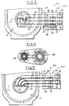
- FIG. 1 is a part sectional elevational view of a multiple plunger glass system embodying the invention.
- FIG. 2 is a fragmentary plan view of the system.
- FIG. 3 is a fragmentary sectional view on an enlarged scale taken along the line 3-3 in FIG. 2.
- FIG. 4 is a sectional view taken along the line 4-4 in FIG. 3.
- FIG. 5 is a fragmentary plan view of a modified form of glass plunger system.
- FIG. 6 is a fragmentary plan view of a further form of glass plunger system.
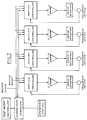
- FIG. 7 is an electronic schematic of the control system.
- FIG. 8 is a diagram of the range of motion of a plurality of plungers.
- the glass plunger system 10 embodying the invention is associated with a bowl 11 of a forehearth and is intended to support a plurality of plungers or needles 12 that function in connection with orifices 13 to control the flow of glass out of the orifices so that when associated shears, not shown, are used the size and weight of the gobs is consistent.
- each plunger 12 issupported by a horizontal arm 15 that is connected to the actuator 16 of a servo-motor controlled mechanism 17.
- Each arm further includes an air spring 18 associated with its respective arm 15 for balancing the weight of each plunger and its respective arm.
- the center lines of the plungers lie generally in a first plane P1.
- the arms 15 have the major portions thereof generally parallel (Fig. 2,5) or perpendicular (Fig. 6) to the plane (P1,P2) of the plungers 12.
- a feedback system (Fig. 7) is provided to monitor the position of each individual plunger independently of the other at all times and make corrections to the actual position of the plunger if desired.
- the arms 15 are constructed and arranged in close proximity so that a minimum of space is utilized and so that the operating mechanisms 17 are in lateral but close proximity to the bowl of the glass.
- one arm 15 is straight and the other three arms are L-shaped, one arm 15 being on one side of straight arm 15 and the other two arm 15 being on the other side of straight arm 15.
- all the L-shaped arme are on one side of the straight arm.
- the configuration and size of the L-shaped arms are such that the arms are substantially equidistance from one another throughout their lengths.
- the arms have their free ands extending at a right angle with the plungers 12 attached thereto with the center lines of the plungers 12 lie in a first plane P1.
- the ends of the arms are curved to provide the center lines of the plungers 12 in a single plane.
- the arms are entirely straight and the center of the plungers are in a plane P2 that is parallel to the planes m1, m2 containing the servo-motors axes.
- the servo-motor assembly comprises a welded drive housing 30 and includes a top bearing collar 31, an intermediate bearing collar 32 and lower bearing collar 33.
- a servo drive shaft 34 is rotatably mounted in the collar 33 by a duplex bearing 35 held in position by retaining nut 36.
- the actuator 16 is in the form of a welded drive post assembly 40 slidably mounted within the housing 30 an linearily driven by a planetary roller nut 41.
- the drive shaft 34 supports a lead screw 42 that is associated with the servo nut 41.
- a coupling 43 connects the shaft 34 to the shaft of the servo actuator 45.
- Coupling 43 is preferably of the keyless bushing type which provide a positive lock between servo actuator shaft 45 and drive shaft 34.
- the keyless bushing allows us the use of the smallest practical shaft diam 34.
- the reduced shaft inertia reduces the motor load allowing us to use the latest art of the industry motors 17.
- Such a coupling is manufactured and sold by Fenner Mannheim, 311 West Stiegel Street, Mannheim, Pennsylvania under the trademark Trantorque.
- Each air cylinder 18 that performs the function of an air spring is provided in close relationship to its respective servo-motor assembly and includes a cylinder housing 50 that has a base ring 51, a cylinder housing 52, a jam nut 53 and an upper cylinder weldment 54.
- An air spring column 55 extends between the shaft of an air spring and a respective arm.
- the multiple orifice plunger control system is made up of one to four separate mechanical systems, depending on the number of plungers to move the needles, depending on the number of needles that are present (1-4). Since each needle is a mechanically independent system, a separate motion control unit must be provided for each unit. Referring to FIG. 7, this unit consists of the motion controller, amplifier/driver, servo actuator (which in this case, is an AC servo motor), and a feedback device (resolver) inside the motor housing. At this level each control system is completely independent.
- the feedback device is mounted on the back of the servo motor and serves a dual purpose. It provides position information to the motion controller which is used to determine both the motor rotor position and the position of the plunger.
- the rotor position is needed for communication of the motor since it is an AC servo motor.
- the position of the plungers is derived from the resolver, and is a relative offset from a fixed reference.
- the fixed reference is the end of travel of the lead screw in the extended position.
- the amplifier/driver is simply a power amplifier. It converts the torque command inputs to the appropriate voltage and power level for the AC servo-motor connected to it.
- the motion controller has in its memory a motion profile, generated by the supervisor, that dictates where the particular needle mechanism should be in relationship to the master clock and reset signals.
- the actual position of the mechanics is determined from the feedback device.
- the motion controller uses both the actual position, the commanded (profile) position and the rotor position to generate the torque commands that go to the amplifier.
- the absolute torque command is calculated as a function of the actual and commanded positions.
- the torque commands that are sent to the amplifier are in a commutated form for phase A and B.
- the amplitude of the absolute torque command for motor phases A & B is adjusted based on the motor rotor position.
- the torque command for phase C is calculated in the amplifier, it is the sum of the torque command of A and B.
- the supervisor calculates the motion profile for each of the motion controllers based on input from the user.
- the profile is a position-to-position relationship between a master clock and the desired position of each needle.
- the same profile is normally used for each needle, but a unique profile for each needle is possible if the situation demands it.
- the needles are normally synchronized to operate at the same time, reaching the extremes of their motion at the same point in time.
- the vertical distance is normally the same also. Because of glass flow differences between the orifices, the needle typically operates at different elevations as shown in FIG. 8. This difference in height is used to balance the weight of the gobs produced by the individual orifices. The height adjustment is controlled by the supervisor.
- the motion profile for the effected needle or needles is recalculated by the supervisor.
- the profile is then written into the memory of the motion controller.
- the supervisor is then responsible for synchronizing the change to the new profile so that all the effected motion controllers switch at the same time without a disruption of production.
- each plunger is individually mounted in association with its respective servo-motor; wherein each servo control can be automatically controlled to produce an accurate weight gob during operation; wherein the actuating servo mechanisms are mounted on the side of the forehearth and cannot contaminate the glass and are protected from the heat of the glass; wherein the individual weight of the plunger and support arms is counterbalanced by an air spring; and wherein a single plunger can be consulted, operated and controlled individually.
Landscapes
- Chemical & Material Sciences (AREA)
- Engineering & Computer Science (AREA)
- Materials Engineering (AREA)
- Organic Chemistry (AREA)
- Fluid-Pressure Circuits (AREA)
- Glass Compositions (AREA)
- Joining Of Glass To Other Materials (AREA)
- Separation Using Semi-Permeable Membranes (AREA)
- Re-Forming, After-Treatment, Cutting And Transporting Of Glass Products (AREA)
- Flow Control (AREA)
- Monitoring And Testing Of Nuclear Reactors (AREA)
- Manufacture Of Motors, Generators (AREA)
- Microscoopes, Condenser (AREA)
- Feeding, Discharge, Calcimining, Fusing, And Gas-Generation Devices (AREA)
- Infusion, Injection, And Reservoir Apparatuses (AREA)
Applications Claiming Priority (2)
| Application Number | Priority Date | Filing Date | Title |
|---|---|---|---|
| US2224293A | 1993-02-25 | 1993-02-25 | |
| US22242 | 1993-02-25 |
Publications (2)
| Publication Number | Publication Date |
|---|---|
| EP0612698A1 true EP0612698A1 (de) | 1994-08-31 |
| EP0612698B1 EP0612698B1 (de) | 1999-09-15 |
Family
ID=21808591
Family Applications (1)
| Application Number | Title | Priority Date | Filing Date |
|---|---|---|---|
| EP94102615A Expired - Lifetime EP0612698B1 (de) | 1993-02-25 | 1994-02-22 | Glasspeisevorrichtung mit mehreren Öffnungen |
Country Status (15)
| Country | Link |
|---|---|
| EP (1) | EP0612698B1 (de) |
| JP (1) | JP2620197B2 (de) |
| KR (1) | KR100317274B1 (de) |
| CN (1) | CN1045942C (de) |
| AT (1) | ATE184582T1 (de) |
| AU (1) | AU676872B2 (de) |
| BR (1) | BR9400664A (de) |
| CA (1) | CA2116148C (de) |
| DE (1) | DE69420598T2 (de) |
| DK (1) | DK0612698T3 (de) |
| EC (1) | ECSP941046A (de) |
| ES (1) | ES2137273T3 (de) |
| GR (1) | GR3031931T3 (de) |
| MX (1) | MX9401332A (de) |
| ZA (1) | ZA941241B (de) |
Cited By (4)
| Publication number | Priority date | Publication date | Assignee | Title |
|---|---|---|---|---|
| EP0771762A1 (de) | 1995-11-03 | 1997-05-07 | Owens-Brockway Glass Container Inc. | Plungernadelvorrichtung für Glasschmelzofen |
| EP0789002A1 (de) * | 1996-02-07 | 1997-08-13 | Owens-Brockway Glass Container Inc. | Glasspeisevorrichtung mit mehreren Öffnungen |
| GB2329381A (en) * | 1997-09-18 | 1999-03-24 | Bh F | Apparatus for extruding molten glass gobs |
| CN111724953A (zh) * | 2020-06-28 | 2020-09-29 | 三瑞科技(江西)有限公司 | 一种钢化玻璃绝缘子的成型、钢化生产 |
Families Citing this family (3)
| Publication number | Priority date | Publication date | Assignee | Title |
|---|---|---|---|---|
| JP4222778B2 (ja) * | 2001-12-14 | 2009-02-12 | Hoya株式会社 | ガラス成形体の製造方法および光学素子の製造方法 |
| DE10254654A1 (de) * | 2002-11-22 | 2004-06-09 | Heinz-Glas Gmbh | Vorrichtung und Verfahren zur Verarbeitung von Glasposten unterschiedlicher Massen und Speisevorrichtung |
| DE102004011647A1 (de) * | 2004-03-10 | 2005-09-29 | Heye International Gmbh | Verfahren und Vorrichtung zur Regelung der Glastropfenmasse bei der Herstellung von Hohlglasbehältern |
Citations (3)
| Publication number | Priority date | Publication date | Assignee | Title |
|---|---|---|---|---|
| US1761372A (en) * | 1922-03-22 | 1930-06-03 | Hazel Atlas Glass Co | Plunger-operating mechanism for glass furnaces |
| US1926764A (en) * | 1930-11-03 | 1933-09-12 | United Glass Bottle Mfg Ltd | Glass feeding apparatus |
| US3313612A (en) * | 1962-05-18 | 1967-04-11 | Putsch & Co H | Motion transmitting means for glass feeder plunger |
Family Cites Families (7)
| Publication number | Priority date | Publication date | Assignee | Title |
|---|---|---|---|---|
| JPS5983940A (ja) * | 1982-11-04 | 1984-05-15 | Nippon Electric Glass Co Ltd | ガラスゴブの供給装置 |
| JPS59146945A (ja) * | 1983-02-08 | 1984-08-23 | Fuso Seikou Kk | ガラス供給装置 |
| US4551163A (en) * | 1984-06-04 | 1985-11-05 | Emhart Industries, Inc. | Electronic glass feeder plunger operating mechanism |
| JPS6230134A (ja) * | 1985-07-31 | 1987-02-09 | Mitsubishi Yuka Fine Chem Co Ltd | 合成樹脂用安定剤 |
| JPH0666938B2 (ja) * | 1985-09-27 | 1994-08-24 | 株式会社東芝 | ビデオテ−プレコ−ダの特殊再生装置 |
| JPH0364451A (ja) * | 1989-07-31 | 1991-03-19 | Sharp Corp | 絶縁膜の製造方法 |
| JPH05139754A (ja) * | 1991-07-09 | 1993-06-08 | Ishizuka Glass Co Ltd | ゴブ生成装置 |
-
1994
- 1994-02-22 DE DE69420598T patent/DE69420598T2/de not_active Expired - Lifetime
- 1994-02-22 DK DK94102615T patent/DK0612698T3/da active
- 1994-02-22 AT AT94102615T patent/ATE184582T1/de active
- 1994-02-22 ES ES94102615T patent/ES2137273T3/es not_active Expired - Lifetime
- 1994-02-22 CA CA002116148A patent/CA2116148C/en not_active Expired - Lifetime
- 1994-02-22 MX MX9401332A patent/MX9401332A/es unknown
- 1994-02-22 AU AU56313/94A patent/AU676872B2/en not_active Expired
- 1994-02-22 EP EP94102615A patent/EP0612698B1/de not_active Expired - Lifetime
- 1994-02-23 ZA ZA941241A patent/ZA941241B/xx unknown
- 1994-02-24 BR BR9400664A patent/BR9400664A/pt not_active IP Right Cessation
- 1994-02-24 EC EC1994001046A patent/ECSP941046A/es unknown
- 1994-02-24 JP JP6049916A patent/JP2620197B2/ja not_active Expired - Lifetime
- 1994-02-24 CN CN94103269A patent/CN1045942C/zh not_active Expired - Lifetime
- 1994-02-24 KR KR1019940003370A patent/KR100317274B1/ko not_active Expired - Lifetime
-
1999
- 1999-11-24 GR GR990403023T patent/GR3031931T3/el unknown
Patent Citations (3)
| Publication number | Priority date | Publication date | Assignee | Title |
|---|---|---|---|---|
| US1761372A (en) * | 1922-03-22 | 1930-06-03 | Hazel Atlas Glass Co | Plunger-operating mechanism for glass furnaces |
| US1926764A (en) * | 1930-11-03 | 1933-09-12 | United Glass Bottle Mfg Ltd | Glass feeding apparatus |
| US3313612A (en) * | 1962-05-18 | 1967-04-11 | Putsch & Co H | Motion transmitting means for glass feeder plunger |
Cited By (9)
| Publication number | Priority date | Publication date | Assignee | Title |
|---|---|---|---|---|
| US5885317A (en) * | 1993-02-25 | 1999-03-23 | Owens-Brockway Glass Container Inc. | Multiple orifice glass feed system |
| US7168270B2 (en) | 1993-02-25 | 2007-01-30 | Owens-Brockway Glass Container Inc. | Multiple orifice glass feed system |
| EP0771762A1 (de) | 1995-11-03 | 1997-05-07 | Owens-Brockway Glass Container Inc. | Plungernadelvorrichtung für Glasschmelzofen |
| EP0789002A1 (de) * | 1996-02-07 | 1997-08-13 | Owens-Brockway Glass Container Inc. | Glasspeisevorrichtung mit mehreren Öffnungen |
| AU717800B2 (en) * | 1996-02-07 | 2000-03-30 | Owens-Brockway Glass Container Inc. | Multiple orifice glass feed system |
| GB2329381A (en) * | 1997-09-18 | 1999-03-24 | Bh F | Apparatus for extruding molten glass gobs |
| WO1999014166A1 (en) | 1997-09-18 | 1999-03-25 | Bh-F (Engineering) Limited | Apparatus for handling molten glass |
| CN111724953A (zh) * | 2020-06-28 | 2020-09-29 | 三瑞科技(江西)有限公司 | 一种钢化玻璃绝缘子的成型、钢化生产 |
| CN111724953B (zh) * | 2020-06-28 | 2021-12-03 | 三瑞科技(江西)有限公司 | 一种钢化玻璃绝缘子的成型、钢化生产 |
Also Published As
| Publication number | Publication date |
|---|---|
| ES2137273T3 (es) | 1999-12-16 |
| ATE184582T1 (de) | 1999-10-15 |
| CA2116148A1 (en) | 1994-08-26 |
| BR9400664A (pt) | 1994-10-04 |
| KR940019621A (ko) | 1994-09-14 |
| DK0612698T3 (da) | 2000-01-10 |
| CA2116148C (en) | 2000-05-02 |
| DE69420598T2 (de) | 2000-05-04 |
| EP0612698B1 (de) | 1999-09-15 |
| AU676872B2 (en) | 1997-03-27 |
| ECSP941046A (es) | 1994-09-16 |
| DE69420598D1 (de) | 1999-10-21 |
| AU5631394A (en) | 1994-09-01 |
| CN1096011A (zh) | 1994-12-07 |
| JPH06247721A (ja) | 1994-09-06 |
| KR100317274B1 (ko) | 2002-02-19 |
| MX9401332A (es) | 1994-08-31 |
| JP2620197B2 (ja) | 1997-06-11 |
| CN1045942C (zh) | 1999-10-27 |
| GR3031931T3 (en) | 2000-03-31 |
| ZA941241B (en) | 1994-09-19 |
Similar Documents
| Publication | Publication Date | Title |
|---|---|---|
| US4551163A (en) | Electronic glass feeder plunger operating mechanism | |
| US4431896A (en) | Method and apparatus for orienting the wire guidance heads on spark erosion cutting equipment for eroding with a great wire slope | |
| US6622526B1 (en) | Multiple orifice glass feed system | |
| EP0612698A1 (de) | Glasspeisevorrichtung mit mehreren Öffnungen | |
| EP4663611A1 (de) | Direktes einspeisen von glastropfen in quer verfahrbare rohlingsformen | |
| CA1313700C (en) | Electronic servo control of glass gob distribution | |
| US5573570A (en) | Glass gob shearing apparatus | |
| EP1050514B1 (de) | Plunjermechanismus zum Pressen von Kübeln aus geschmolzenem Glas in der Vorform einer I.S. Maschine zur Herstellung von Hohlglasgegenständen | |
| KR100295424B1 (ko) | 본딩하중의보정방법및와이어본딩장치 | |
| US1961894A (en) | Automatic control system | |
| MXPA97000935A (en) | Multip holes glass feeding system | |
| CA1236902A (en) | Electronic glass feeder plunger operating mechanism | |
| EP0872455B1 (de) | Glaskülbelschneidevorrichtung mit Dämpfung des Glasscherenmechanismus | |
| US5545244A (en) | Control for glass forming machine | |
| US5122179A (en) | Glassware making machine | |
| EP3867202B1 (de) | Kolbenanordnung zur formung von bändern aus geschmolzenem glas | |
| JP2533801B2 (ja) | プレスブレ―キ | |
| CA2533405C (en) | Glass gob shearing apparatus |
Legal Events
| Date | Code | Title | Description |
|---|---|---|---|
| PUAI | Public reference made under article 153(3) epc to a published international application that has entered the european phase |
Free format text: ORIGINAL CODE: 0009012 |
|
| AK | Designated contracting states |
Kind code of ref document: A1 Designated state(s): AT BE CH DE DK ES FR GB GR IE IT LI LU MC NL PT SE |
|
| 17P | Request for examination filed |
Effective date: 19950127 |
|
| 17Q | First examination report despatched |
Effective date: 19970408 |
|
| APAB | Appeal dossier modified |
Free format text: ORIGINAL CODE: EPIDOS NOAPE |
|
| APAB | Appeal dossier modified |
Free format text: ORIGINAL CODE: EPIDOS NOAPE |
|
| APBJ | Interlocutory revision of appeal recorded |
Free format text: ORIGINAL CODE: EPIDOS IRAPE |
|
| GRAG | Despatch of communication of intention to grant |
Free format text: ORIGINAL CODE: EPIDOS AGRA |
|
| GRAG | Despatch of communication of intention to grant |
Free format text: ORIGINAL CODE: EPIDOS AGRA |
|
| GRAH | Despatch of communication of intention to grant a patent |
Free format text: ORIGINAL CODE: EPIDOS IGRA |
|
| GRAH | Despatch of communication of intention to grant a patent |
Free format text: ORIGINAL CODE: EPIDOS IGRA |
|
| GRAA | (expected) grant |
Free format text: ORIGINAL CODE: 0009210 |
|
| ITF | It: translation for a ep patent filed | ||
| AK | Designated contracting states |
Kind code of ref document: B1 Designated state(s): AT BE CH DE DK ES FR GB GR IE IT LI LU MC NL PT SE |
|
| REF | Corresponds to: |
Ref document number: 184582 Country of ref document: AT Date of ref document: 19991015 Kind code of ref document: T |
|
| REG | Reference to a national code |
Ref country code: CH Ref legal event code: EP |
|
| ET | Fr: translation filed | ||
| REF | Corresponds to: |
Ref document number: 69420598 Country of ref document: DE Date of ref document: 19991021 |
|
| REG | Reference to a national code |
Ref country code: IE Ref legal event code: FG4D |
|
| REG | Reference to a national code |
Ref country code: ES Ref legal event code: FG2A Ref document number: 2137273 Country of ref document: ES Kind code of ref document: T3 |
|
| REG | Reference to a national code |
Ref country code: CH Ref legal event code: NV Representative=s name: BOVARD AG PATENTANWAELTE |
|
| REG | Reference to a national code |
Ref country code: DK Ref legal event code: T3 |
|
| REG | Reference to a national code |
Ref country code: PT Ref legal event code: SC4A Free format text: AVAILABILITY OF NATIONAL TRANSLATION Effective date: 19991206 |
|
| PLBE | No opposition filed within time limit |
Free format text: ORIGINAL CODE: 0009261 |
|
| STAA | Information on the status of an ep patent application or granted ep patent |
Free format text: STATUS: NO OPPOSITION FILED WITHIN TIME LIMIT |
|
| 26N | No opposition filed | ||
| REG | Reference to a national code |
Ref country code: GB Ref legal event code: IF02 |
|
| PGFP | Annual fee paid to national office [announced via postgrant information from national office to epo] |
Ref country code: LU Payment date: 20061219 Year of fee payment: 14 |
|
| PGFP | Annual fee paid to national office [announced via postgrant information from national office to epo] |
Ref country code: MC Payment date: 20070115 Year of fee payment: 14 |
|
| PG25 | Lapsed in a contracting state [announced via postgrant information from national office to epo] |
Ref country code: MC Free format text: LAPSE BECAUSE OF NON-PAYMENT OF DUE FEES Effective date: 20080228 |
|
| PG25 | Lapsed in a contracting state [announced via postgrant information from national office to epo] |
Ref country code: LU Free format text: LAPSE BECAUSE OF NON-PAYMENT OF DUE FEES Effective date: 20080222 |
|
| REG | Reference to a national code |
Ref country code: CH Ref legal event code: PFA Owner name: OWENS-BROCKWAY GLASS CONTAINER INC. Free format text: OWENS-BROCKWAY GLASS CONTAINER INC.#ONE SEA GATE#TOLEDO, OHIO 43666 (US) -TRANSFER TO- OWENS-BROCKWAY GLASS CONTAINER INC.#ONE SEA GATE#TOLEDO, OHIO 43666 (US) |
|
| PGFP | Annual fee paid to national office [announced via postgrant information from national office to epo] |
Ref country code: IT Payment date: 20120222 Year of fee payment: 19 |
|
| PGFP | Annual fee paid to national office [announced via postgrant information from national office to epo] |
Ref country code: DE Payment date: 20130227 Year of fee payment: 20 Ref country code: DK Payment date: 20130225 Year of fee payment: 20 Ref country code: IE Payment date: 20130226 Year of fee payment: 20 Ref country code: ES Payment date: 20130226 Year of fee payment: 20 Ref country code: FR Payment date: 20130311 Year of fee payment: 20 Ref country code: GB Payment date: 20130227 Year of fee payment: 20 Ref country code: SE Payment date: 20130227 Year of fee payment: 20 Ref country code: CH Payment date: 20130225 Year of fee payment: 20 |
|
| PGFP | Annual fee paid to national office [announced via postgrant information from national office to epo] |
Ref country code: NL Payment date: 20130224 Year of fee payment: 20 Ref country code: BE Payment date: 20130227 Year of fee payment: 20 Ref country code: GR Payment date: 20130226 Year of fee payment: 20 |
|
| PGFP | Annual fee paid to national office [announced via postgrant information from national office to epo] |
Ref country code: PT Payment date: 20130205 Year of fee payment: 20 Ref country code: AT Payment date: 20130201 Year of fee payment: 20 |
|
| REG | Reference to a national code |
Ref country code: DE Ref legal event code: R071 Ref document number: 69420598 Country of ref document: DE |
|
| REG | Reference to a national code |
Ref country code: DK Ref legal event code: EUP Effective date: 20140222 |
|
| REG | Reference to a national code |
Ref country code: DE Ref legal event code: R071 Ref document number: 69420598 Country of ref document: DE |
|
| BE20 | Be: patent expired |
Owner name: *OWENS-BROCKWAY GLASS CONTAINER INC. Effective date: 20140222 |
|
| REG | Reference to a national code |
Ref country code: CH Ref legal event code: PL |
|
| REG | Reference to a national code |
Ref country code: PT Ref legal event code: MM4A Free format text: MAXIMUM VALIDITY LIMIT REACHED Effective date: 20140222 |
|
| REG | Reference to a national code |
Ref country code: NL Ref legal event code: V4 Effective date: 20140222 |
|
| REG | Reference to a national code |
Ref country code: GB Ref legal event code: PE20 Expiry date: 20140221 |
|
| REG | Reference to a national code |
Ref country code: IE Ref legal event code: MK9A |
|
| REG | Reference to a national code |
Ref country code: SE Ref legal event code: EUG |
|
| REG | Reference to a national code |
Ref country code: AT Ref legal event code: MK07 Ref document number: 184582 Country of ref document: AT Kind code of ref document: T Effective date: 20140222 |
|
| REG | Reference to a national code |
Ref country code: GR Ref legal event code: MA Ref document number: 990403023 Country of ref document: GR Effective date: 20140223 |
|
| PG25 | Lapsed in a contracting state [announced via postgrant information from national office to epo] |
Ref country code: GB Free format text: LAPSE BECAUSE OF EXPIRATION OF PROTECTION Effective date: 20140221 Ref country code: IE Free format text: LAPSE BECAUSE OF EXPIRATION OF PROTECTION Effective date: 20140222 Ref country code: DE Free format text: LAPSE BECAUSE OF EXPIRATION OF PROTECTION Effective date: 20140225 |
|
| PG25 | Lapsed in a contracting state [announced via postgrant information from national office to epo] |
Ref country code: PT Free format text: LAPSE BECAUSE OF EXPIRATION OF PROTECTION Effective date: 20140304 |
|
| REG | Reference to a national code |
Ref country code: ES Ref legal event code: FD2A Effective date: 20140925 |
|
| PG25 | Lapsed in a contracting state [announced via postgrant information from national office to epo] |
Ref country code: ES Free format text: LAPSE BECAUSE OF EXPIRATION OF PROTECTION Effective date: 20140223 |