EP0612655B1 - Procédé et unité pour jeter des ancres et pour l'amarrage des plate-formes - Google Patents
Procédé et unité pour jeter des ancres et pour l'amarrage des plate-formes Download PDFInfo
- Publication number
- EP0612655B1 EP0612655B1 EP94107349A EP94107349A EP0612655B1 EP 0612655 B1 EP0612655 B1 EP 0612655B1 EP 94107349 A EP94107349 A EP 94107349A EP 94107349 A EP94107349 A EP 94107349A EP 0612655 B1 EP0612655 B1 EP 0612655B1
- Authority
- EP
- European Patent Office
- Prior art keywords
- chain
- platform
- cable
- laying
- line
- Prior art date
- Legal status (The legal status is an assumption and is not a legal conclusion. Google has not performed a legal analysis and makes no representation as to the accuracy of the status listed.)
- Expired - Lifetime
Links
Images


Classifications
-
- B—PERFORMING OPERATIONS; TRANSPORTING
- B63—SHIPS OR OTHER WATERBORNE VESSELS; RELATED EQUIPMENT
- B63B—SHIPS OR OTHER WATERBORNE VESSELS; EQUIPMENT FOR SHIPPING
- B63B21/00—Tying-up; Shifting, towing, or pushing equipment; Anchoring
- B63B21/04—Fastening or guiding equipment for chains, ropes, hawsers, or the like
-
- B—PERFORMING OPERATIONS; TRANSPORTING
- B63—SHIPS OR OTHER WATERBORNE VESSELS; RELATED EQUIPMENT
- B63B—SHIPS OR OTHER WATERBORNE VESSELS; EQUIPMENT FOR SHIPPING
- B63B21/00—Tying-up; Shifting, towing, or pushing equipment; Anchoring
- B63B21/22—Handling or lashing of anchors
-
- B—PERFORMING OPERATIONS; TRANSPORTING
- B63—SHIPS OR OTHER WATERBORNE VESSELS; RELATED EQUIPMENT
- B63B—SHIPS OR OTHER WATERBORNE VESSELS; EQUIPMENT FOR SHIPPING
- B63B21/00—Tying-up; Shifting, towing, or pushing equipment; Anchoring
- B63B21/50—Anchoring arrangements or methods for special vessels, e.g. for floating drilling platforms or dredgers
-
- B—PERFORMING OPERATIONS; TRANSPORTING
- B63—SHIPS OR OTHER WATERBORNE VESSELS; RELATED EQUIPMENT
- B63B—SHIPS OR OTHER WATERBORNE VESSELS; EQUIPMENT FOR SHIPPING
- B63B21/00—Tying-up; Shifting, towing, or pushing equipment; Anchoring
- B63B21/22—Handling or lashing of anchors
- B63B2021/225—Marker buoys for indicating position of an anchor, or for providing a line connection between the anchor and the water surface
Definitions
- This invention concerns a system for the casting of anchors intended to moor floating drilling and producing oil rigs, for which an anchor casting unit is used that is specially designed to store all the material usually kept on the platform for such purpose.
- Such unit is equipped to enable anchors and cables to be cast beforehand continuously, to enable line tautness tests to be carried out, and to enable cables to be fastened to platform chains when the platform is being positioned.
- the conventional method of mooring floating offshore drilling and production platforms uses a combination of chains and large gauge cables, which means that platforms must be provided with storage space and heavy-lift cranes to handle them.
- platforms must be provided with storage space and heavy-lift cranes to handle them.
- at least eight mooring lines are needed, and two main winches are needed for each mooring line.
- the chains, cables and anchors are stored on board the platform and they are dropped by transferring the anchor, already fastened to its chain, into a special kind of tug with the aid of a device known as an anchor chaser tied to a tug hawser. After such transfer the tug travels away from the platform to wherever it has been agreed upon beforehand that the anchor is to be dropped, thereby towing the chain that the windlass on the platform has released.
- This invention aims to produce an improved solution to such problems.
- One object of this invention is to provide an anchor-casting craft able to store all the gear needed to cast the anchors which are to be taken off the platform deck; such craft are equipped to enable all of the anchors, chains and cables to be cast overboard beforehand and the lines tested for tension, and afterwards for cables to be fastened to production or drilling platform chains upon positioning of such platform on station.
- one aspect of the present invention provides a platform-mooring process, characterised by the following steps:- recovering, with the aid of laying craft, standby buoy, and chain windlass, the line to be dealt with and fastening an auxiliary cable thereto; shifting the laying craft towards the platform while laying auxiliary cable, and picking up close to the platform the end of the second part of the platform chain which is fastened to the laying craft chain, where one joins the other, with the aid of a triple link; after fastening is finished, laying a suitable length of chain from the platform while the laying craft starts to pick up the laid cable, up to where fastening of such cable to the line rises to the level of the working platform, and locking the cable capstan drum; fastening triple links of the chain and cable, respectively, lying more or less at the same level, such fastening being effected by introducing a small length of chain together with a laying device which helps in the lowering of the fastened line down to its place in the sag; after completion of the fasten
- US-A-4348975 discloses a vessel having a winch 22 for cable to assist in laying an anchor attached to that cable, and also includes disclosure of on-deck storage for buoys to be used during anchor laying.
- the pre-characterising portion of claim 1 is based on the disclosure of this US document.
- GB-A-1471131 discloses a ship having storage for a plurality of chains.
- a second aspect of the invention provides a laying device for lowering anchoring lines in a platform mooring device characterised by consisting of a support base; and a sheave crown which fits on said support base by means of a spindle, said crown having notches in its lateral flanges to act as guides for breakable ropes which are fixed, at one end, into a common lug, and then in the middle of the ropes are moved away by a guide mounted on said spindle, and which at the other end are held by individual turnbuckles, said breakable ropes enabling links of chain to be tied to said sheave crown at different angles.
- This invention consists of a process for use in the mooring of floating production or drilling rigs.
- the process uses a craft equipped so as to enable anchors, chains and cables to be cast overboard beforehand, and the lines to be tested for tension, and then afterwards such cable can be fastened to the producing or drilling platform chains when such platforms are being positioned on station.
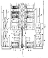
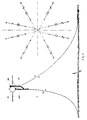
- Figure 1 represents the general layout of the deck of such a dropping craft 1, on which anchors 2 in their wells 3 are shown, as is a capstan 4 for chains 5, and two improved kinds of drums 6 for steel cable 7 operated by drive 8 from motors 9.
- Chains 5 are stowed in lockers 10 built into the underside of the deck of the craft, and are led to the capstan 4, or back to the lockers 10, along hawsepipes 11 optionally under power to make return into the lockers easier.
- Cable 7 is wound on stowage drums 12 mounted on a bed 13, which drums are provided with devices, also power-driven, and brakes and fairleads (not shown in Figure 1), to enable cable 7 wound on the improved drums 6 of capstans 4 to be paid out when casting, and the opposite sense when mooring cables are being brought in or exchanged.
- the capacity of the improved drums 6 and of the stowage drums 12 is high, though practical and economical enough to enable long stretches of rope to be laid; even greater lengths may be laid if formed of several lengths joined together.
- the main buoys 14 lie on their rails 15 and the buoys of smaller size and lesser weight, anchors and anchor weights can be left on deck, within cribs or special beds. In order to make it easier to shift such gear on deck, a mobile track-laying crane may be provided.
- a frame 16 bears a full-length girder along which any required sheaves and running tackle are provided.
- Working platform 18 mounted aft of the craft 19, runs on rails 20 and is powered to enable it to take up any position across the stern of the craft whenever cables and chains are being fastened or unfastened, and the platform may be provided with wedges for the chains and cable to help such operations.
- the cable 7 in the middle of the mooring line is provided with loops 21 and 22 at either end, for fastening to the two lengths of chain or to a standby buoy, as will be explained later with reference to the anchor-dropping system.
- a loop 22 should lie on the working platform 18 aft of the craft, waiting to be fastened subsequently. Placing of the loop 22 cannot however be performed with the aid of an extension to the cable (for instance, a smaller gauge one), since the dimensions of not only the loops but also the fastening accessories lying on the first few turns of cable on the drum when being wound, are of a given size, and this would lead not only to the subsequent turns being unevenly wound but also, worse still, to damage brought about by squeezing and twisting which is fatal to the life of cables.
- an extension to the cable for instance, a smaller gauge one
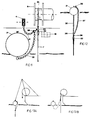
- capstans for mooring cable are provided with an improved kind of drum which is divided into two parts (an auxiliary part A and a main part B), by means of a central flange in the middle 23 including a groove 24 to receive a cable 7 passing from one part A to the other B.
- the auxiliary part A which holds less cable, has a hub which is narrower than that of the main part B, such difference in the diameter of the hub being meant to stow the extension cable 25 (of smaller gauge) which is wound on this part until the build-up of cable 25 grows to give the hub of part A the same effective diameter as that of the hub of the main part B, thereby diminishing any risk of twisting.
- the diameter of the root of the groove 24 is the same as that of the hub of the main part B.
- the main cable 7 shifts from the main part B to the auxiliary part A where it is fastened to the extension cable 25 (by means of a triple link 26 and other conventional accessories lying outside the main part B) which will lead loop 22 to the working platform 18. Because of all this, the shape of all stowage drums 12 must be the same.
- Anchors are laid in pairs so as to lie (approximately) opposite to one another, as regards the mid-point of the array (the rig site), in order to enable line pulling tests to be carried out as will also be dealt with later herein.
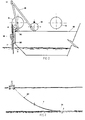
- FIG. 5 The manner of laying the anchors in accordance with this invention is shown in Figures 5 and 12.
- the anchor 2 is first of all shifted out of its well, already fastened to the end of the chain 5, and is brought in front of the chain capstan 4 with the aid of the travelling block and tackle 27.
- the weight of the anchor 2 is transferred to the chain 5, and the block and tackle 27 is released for paying out (Figure 6A) and a start made on casting the chain 5 overboard (Figure 6B).
- the length of chain 5 to be dropped is measured not only by instruments but also visually when the special triple link 28 (Figure 6C) arrives at the edge of the working platform 18 ( Figure 5), whereupon the loop 21 at the end of cable 7 is fastened to it.
- an extra length of chain (extension 29 in Figure 6D) is cast in order to transfer the weight of the chain 5 to the cable 7 ( Figure 6D), and the fastening is then hoisted (this time by means of the cable drum) up to the level of the working platform 18, in order to release the extension chain 29 from the chain 5.
- Operation goes ahead, in that the cable 7 is cast, and the total length of line already dropped (chain 5 and cable 7) is controlled until the anchor 2 reaches the sea bed ( Figure 6E), whereupon the laying craft 1 should be lying over the position agreed upon for the anchoring point.
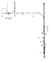
- the craft 1 After the cable has been laid, the craft 1 will be a certain distance away from the standby buoy as shown in Figure 9.
- Buoy 31 is brought close to the laying craft 1 and the rope 35 is pulled by means of the auxiliary capstan, then fastened to the buoy 31 with the help of the tug.
- the buoy 31 Once the buoy 31 has been reached it is moored to the craft 1 and the auxiliary windlass is released for rotation.
- the triple link 36 of extension chain 37 to the hanging cable 30 of the buoy 31 is brought to the level of the working platform 18.
- the extension 29 of the chain is fastened so as, with the aid of windlass 4, to bring plate 38 of the buoy hanging cable 30 up to the level of the working platform 18 to enable it to be fastened to the triple link 26 of cable 7 ( Figure 11).
- the procedure is the same if a hanging rope is used (with the main rope laid on the sea bottom) for mooring to the buoy.
- the mooring test should be carried out by pulling, with the laying craft winches, one line against the other at a preset force.
- the test is carried out by mooring the first line of the pair directly on to the standby buoy, while the second line is being laid.
- the second line has been laid its end is fastened to a cable of the same gauge and length (second drum) and the operation goes on as described, this other cable now being laid being intended for the first line standby buoy.
- the first line is fastened to the chain extension of the winch, and the buoy is released.
- the laying craft 1 now returns, picking up the cable and laying the chain, until it comes to a predetermined point.
- the chain is locked and the first pull made with the cable capstan drawing on the second line; the brake is then applied to the winch drum and the second line is pulled, using the first line capstan, until a set force is achieved; this state is kept up for the time defined under the test.
- the pull in the lines is eased, first of all by slackening the chain (to diminish the pull) and then by slackening the cable.
- the next step starts off with picking up the chain while at the same time laying the cable (again), up to the end of the first line; then the chain is unfastened and the cable is tied on to the buoy directly (or by means of a hanging cable).
- the craft 1 starts picking up the auxiliary cable until it gets to the end of the second line and ties it to its standby buoy.
- the platform mooring procedure is shown in Figures 13A-13H.
- the laying craft 1 picks up the line that is to be dealt with at the standby buoy (Figure 13A), and fastens the auxiliary cable to it (Figure 13B).
- Craft 1 then moves off bound for the platform while laying an auxiliary cable (Figure 13C) and taking on, close to the platform, the end of the second part of the platform chain, which is then fastened to the laying craft chain.
- a triple link 39 ( Figure 13D) is introduced where the two chains meet.
- the line is lowered until it reaches its spot in the sag and the laying device 41 is recovered.
- this device prevents any slipping and/or falling of the line which, owing to its weight, might mean a jerk that could seriously damage the platform and its capstan.
- this work cannot be done with the aid of any of the chasers currently available on the market since they have no kind of locking arrangement to prevent any slipping of the line supported thereby.
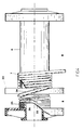
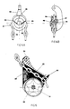
- Figures 14A and 14B provide details of the improved laying device 41 according to this invention, as illustrated in Figure 13G, and specially meant for this operation.
- the device consists of a bearing base 42, and a sheave crown 43 which fits in the bearing base 42 by means of a spindle 44.
- notches 45 which act as guides for breakable ropes 46 (two of them) which are fixed in the following way:- at one end they are fixed to a common central lug 47, their central sections are guided radially outwardly from the sheave spindle by a guide 48 mounted on spindle 44, and at their other ends they are fixed to individual turnbuckles; the breakable ropes thus enable links of chain to be tied to the sheave crown 43 at different angles.
- the chain wrapped around the sheave crown 43 tends to spread out, links at the topmost side of the sag shifting away from it first of all.
- the strength (size) of the breakable ropes 46 is such as to ensure that the chain is held, but they are unable to withstand the weight of the line when the held link begins to shift away from the sheave crown. Thus, when the last breakable rope bursts, the line will have practically reached its point in the sag and any sliding or slipping of the improved laying device 41 will not harm the platform or capstan.
- the line fisher 49 consists of a sheave and crown 50 held in place by a spindle 51 which passes through the body 52 of the fisher, there being in the upper half of the fisher, in the reinforced part thereof, a hoisting eye 53 in the shape of an inverted groove which slides over the chain, a flared front part 54 which acts as a guide, and a nozzle-shaped back part 55 through which only one link at a time of the chain can pass.
- such improved line fisher 49 is fitted into the platform chain (second part) below fenders 56 lying at the water line of the floating platform and is fastened to the platform by means of a hanging cable 57.
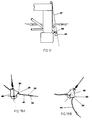
- the hanging cable 57 is delivered (with the aid of a crane) to laying craft 1 lying close to the platform on which the hanging rope is fastened to the cable of the main drum of the platform capstan, and by means of which it is lowered until it gets to the meeting point.
- the line fisher 49 is lowered the laying craft 1 is shifted along the route of the line so as to keep the cable more or less vertically over the line fisher 49.
- the nozzle 55 gets to the first triple link 39 ( Figure 18A) of the fastening, the line fisher will be in place for hoisting.
- the craft 1 should continue to travel along its route and reach a position where it is able to pull the line fisher 49 towards the lowest side of the sag (Figure 18B), whereupon the groove will lift and the hoisting eye 55 will wrap the chain around, and fit it into, the sheave crown 50 as the line is being hoisted ( Figure 18C).
- the triple link 39 is fastened to the chain (or extension) of the laying craft 1, the weight of line being transferred to the craft.
- the line fisher 49 is fastened directly on to a block and tackle or other holding means; the cable of the line fisher is unfastened and tied to the triple link 26 where the chain part 40 joins the previously laid cable ( Figure 18C). Then the part 40 of the chain is unfastened and put on to the craft 1 and, where a procedure opposite to that described above is concerned, previously laid line is fastened to the platform, it is returned to the end of the chain together with the fisher on to the platform.
- the craft 1 then picks up the laid cable while getting closer to the platform, fastens and transfers the end of the previously laid cable that is to be recovered, to the extension cable of the second main drum (then empty) so as to start recovery work. All work after this is a repetition of what has already been described above, including lowering of the line already fastened to the platform, down to the level of the sag, at the end of the operation.
Landscapes
- Chemical & Material Sciences (AREA)
- Engineering & Computer Science (AREA)
- Combustion & Propulsion (AREA)
- Mechanical Engineering (AREA)
- Ocean & Marine Engineering (AREA)
- Laying Of Electric Cables Or Lines Outside (AREA)
- Devices Affording Protection Of Roads Or Walls For Sound Insulation (AREA)
- Revetment (AREA)
- Dry Shavers And Clippers (AREA)
- Magnetic Heads (AREA)
- Conveying And Assembling Of Building Elements In Situ (AREA)
- Unwinding Of Filamentary Materials (AREA)
- Bridges Or Land Bridges (AREA)
- Load-Engaging Elements For Cranes (AREA)
- Emergency Lowering Means (AREA)
- Electric Cable Installation (AREA)
- Ropes Or Cables (AREA)
- Piles And Underground Anchors (AREA)
- Foundations (AREA)
Claims (6)
- Procédé d'amarrage de plate-forme, caractérisé en ce qu'il comporte les étapes suivantes consistant àrécupérer, à l'aide d'une embarcation de mouillage, d'une bouée en attente, et d'un treuil à chaîne, la ligne à mettre en oeuvre et lui fixer un câble auxiliaire, déplacer l'embarcation de mouillage vers la plate-forme en mouillant le câble auxiliaire, et attraper près de la plate-forme l'extrémité de la seconde partie de la chaîne de la plate-forme qui est fixée à la chaîne de l'embarcation de mouillage, où l'une se joint à l'autre, à l'aide d'un maillon triple ; après la fin de la fixation, mouiller une longueur appropriée de chaîne depuis la plate-forme tandis que l'embarcation de mouillage part pour attraper le câble mouillé, jusqu'où la fixation de ce câble à la ligne remonte au niveau de la plate-forme de travail, et verrouiller le tambour-cabestan du câble ; fixer des maillons triples de la chaîne et du câble, respectivement, plus ou moins au même niveau, cette fixation étant effectuée en introduisant une petite longueur de chaîne avec un dispositif de mouillage qui aide à l'abaissement de la ligne fixée vers sa place dans la courbe de flexion ; après achèvement de la fixation, transférer les poids de la chaîne et du câble au dispositif de mouillage, détacher la chaîne de l'embarcation de mouillage et des maillons du câble auxiliaire et attacher le câble auxiliaire audit dispositif de mouillage et transférer le poids du dispositif de mouillage au câble auxiliaire, libérer ledit dispositif de mouillage des moyens utilisés pour le supporter, abaisser la ligne à son niveau dans la courbe de flexion, et récupérer ledit dispositif de mouillage.
- Procédé d'amarrage de plate-forme selon la revendication 1, caractérisé en ce que ledit dispositif de mouillage consiste en une base support ; et un chapeau de poulie qui est monté sur ladite base support au moyen d'une broche, ledit chapeau ayant des encoches dans ses joues latérales pour servir de guides à des cordons cassables qui sont fixés, à une extrémité, dans un point d'attache commun, et puis dans le milieu des cordons sont écartés par un guide monté sur ledit axe, et qui à l'autre extrémité sont maintenus par des tendeurs individuels, lesdits cordons cassables permettant aux maillons de chaîne d'être reliés audit chapeau de poulie à différents angles.
- Procédé d'amarrage de plate-forme selon la revendication 1 ou 2, caractérisé en ce qu'un déplacement de l'ancre en vue de vérifier régulièrement ou remplacer tout organe dans la ligne d'amarrage est effectué à l'aide de ladite embarcation de mouillage, ladite ligne étant hissée à la fixation de la seconde partie de la chaîne depuis la plate-forme vers le câble (partie centrale) au moyen d'un organe de repêchage de ligne.
- Procédé d'amarrage de plate-forme selon la revendication 3, caractérisé en ce que ledit organe de repêchage de ligne consiste en une poulie et un chapeau fixés au moyen d'une broche qui passe à travers un corps dont une partie est renforcée et sous la forme d'un canal retourné ; et en ce que ledit corps a une partie avant qui est plus ouverte afin de guider la chaîne, et une partie arrière ayant une embouchure de guidage et une butée qui empêche un maillon triple de la chaîne de passer à travers ladite embouchure de guidage.
- Un procédé d'amarrage de plate-forme selon la revendication 3 ou 4, caractérisé en ce que ledit organe de repêchage de ligne est placé dans une seconde partie de la chaîne de plate-forme, en dessous de protections disposées à la ligne de flottaison de ladite plate-forme et fixé à la plate-forme par un câble de suspension.
- Dispositif de mouillage pour abaisser des lignes d'ancrage dans un dispositif d'amarrage de plate-forme caractérisé en ce qu'il consiste en une base support (42) ; et un chapeau de poulie (43) qui se monte sur ladite base support au moyen d'une broche, ledit chapeau ayant des encoches (45) dans ses joues latérales pour servir de guides pour des cordons cassables (46) qui sont fixés, à une extrémité, dans un point d'attache (47) commun, et puis dans le milieu des cordons sont écartés par un guide (48) monté sur ladite broche, et qui à l'autre extrémité sont maintenus par des tendeurs individuels, lesdits cordons cassables permettant à des maillons de chaîne d'être suspendus audit chapeau de poulie à différents angles.
Applications Claiming Priority (3)
| Application Number | Priority Date | Filing Date | Title |
|---|---|---|---|
| BR9000135 | 1990-01-15 | ||
| BR909000135A BR9000135A (pt) | 1990-01-15 | 1990-01-15 | Sistema de lancamento de ancoras e amarracao de plataformas e unidade de lancamento de ancoras |
| EP91300261A EP0438258B1 (fr) | 1990-01-15 | 1991-01-15 | Procédés et unité pour jeter des ancres et pour l'amarrage des plates-formes |
Related Parent Applications (1)
| Application Number | Title | Priority Date | Filing Date |
|---|---|---|---|
| EP91300261.4 Division | 1991-01-15 |
Publications (3)
| Publication Number | Publication Date |
|---|---|
| EP0612655A2 EP0612655A2 (fr) | 1994-08-31 |
| EP0612655A3 EP0612655A3 (fr) | 1994-11-09 |
| EP0612655B1 true EP0612655B1 (fr) | 1997-11-19 |
Family
ID=4048731
Family Applications (3)
| Application Number | Title | Priority Date | Filing Date |
|---|---|---|---|
| EP94119597A Expired - Lifetime EP0653349B1 (fr) | 1990-01-15 | 1991-01-15 | Capteur de câble pour le positionnement d'ancres |
| EP91300261A Expired - Lifetime EP0438258B1 (fr) | 1990-01-15 | 1991-01-15 | Procédés et unité pour jeter des ancres et pour l'amarrage des plates-formes |
| EP94107349A Expired - Lifetime EP0612655B1 (fr) | 1990-01-15 | 1991-01-15 | Procédé et unité pour jeter des ancres et pour l'amarrage des plate-formes |
Family Applications Before (2)
| Application Number | Title | Priority Date | Filing Date |
|---|---|---|---|
| EP94119597A Expired - Lifetime EP0653349B1 (fr) | 1990-01-15 | 1991-01-15 | Capteur de câble pour le positionnement d'ancres |
| EP91300261A Expired - Lifetime EP0438258B1 (fr) | 1990-01-15 | 1991-01-15 | Procédés et unité pour jeter des ancres et pour l'amarrage des plates-formes |
Country Status (11)
| Country | Link |
|---|---|
| US (1) | US5522336A (fr) |
| EP (3) | EP0653349B1 (fr) |
| JP (1) | JP2562235B2 (fr) |
| KR (1) | KR100189788B1 (fr) |
| BR (1) | BR9000135A (fr) |
| CA (1) | CA2032609A1 (fr) |
| DE (3) | DE69128256D1 (fr) |
| DK (2) | DK0438258T3 (fr) |
| ES (2) | ES2105479T3 (fr) |
| FI (1) | FI101280B1 (fr) |
| NO (2) | NO307292B1 (fr) |
Families Citing this family (19)
| Publication number | Priority date | Publication date | Assignee | Title |
|---|---|---|---|---|
| GB2304319B (en) * | 1995-08-15 | 1997-10-22 | Gec Alsthom Ltd | Method and apparatus for paying out, securing and hauling in a flexible elongate tensile member |
| US5779226A (en) * | 1996-03-15 | 1998-07-14 | Wudtke; Donald J. | Anchoring system |
| AU8149098A (en) * | 1997-06-19 | 1999-01-04 | Fmc Corporation | Looped mooring line and method of installation |
| US6095075A (en) * | 1998-10-09 | 2000-08-01 | Leslea C. Gordon | Retractable boat line |
| US6325010B1 (en) | 2000-03-29 | 2001-12-04 | Power Vent Technologies, Inc. | Method of vessel propulsion with coordinated bow propulsion |
| EP1283158A1 (fr) * | 2001-08-06 | 2003-02-12 | Single Buoy Moorings Inc. | Procédé d'installation de ligne d'ancrage et connecteur associé |
| CA2397926C (fr) * | 2002-09-11 | 2004-08-24 | Leslea C. Gordon | Retracteur de ligne d'amarre |
| US7036601B2 (en) | 2002-10-06 | 2006-05-02 | Weatherford/Lamb, Inc. | Apparatus and method for transporting, deploying, and retrieving arrays having nodes interconnected by sections of cable |
| NO324808B1 (no) | 2005-03-22 | 2007-12-10 | Advanced Prod & Loading As | System for for fortøyning |
| US7543800B2 (en) * | 2006-08-01 | 2009-06-09 | W.W. Patterson Company | Single stack manual marine winch |
| NO337497B1 (no) * | 2013-02-15 | 2016-04-25 | Gva Consultants Ab | System og fremgangsmåte for utslipp av avfallsfluid |
| SE538099C2 (sv) * | 2013-04-12 | 2016-03-01 | Bassoe Technology Ab | Ett förtöjningssystem |
| CN103482515B (zh) * | 2013-09-27 | 2016-03-09 | 捷胜海洋装备股份有限公司 | 具有导线轮的拖缆绞车 |
| CN103482514B (zh) * | 2013-09-27 | 2015-12-09 | 捷胜海洋装备股份有限公司 | 拖缆绞车 |
| CN103616173B (zh) * | 2013-11-27 | 2016-03-30 | 江苏科技大学 | 一种拉力试验机用的辅助拉力车 |
| KR101598694B1 (ko) * | 2014-05-21 | 2016-02-29 | 대우조선해양 주식회사 | 계류 장치를 갖는 선미 구조 및 이를 갖는 드릴쉽 |
| CN110481708B (zh) * | 2019-09-26 | 2024-04-02 | 东营鑫奥船舶设备制造有限公司 | 一种船锚支架 |
| CN112548523B (zh) * | 2020-11-27 | 2021-10-29 | 江苏科技大学 | 机械手锚链横档定位装置及工作方法 |
| CN112937760B (zh) * | 2021-01-29 | 2023-06-20 | 中海石油(中国)有限公司深圳分公司 | 一种系泊大缆摩擦链防脱装置和方法 |
Family Cites Families (23)
| Publication number | Priority date | Publication date | Assignee | Title |
|---|---|---|---|---|
| GB471562A (fr) * | 1900-01-01 | |||
| US3111926A (en) * | 1961-12-07 | 1963-11-26 | Shell Oil Co | Apparatus for anchoring underwater vessels |
| GB1178067A (en) * | 1967-08-24 | 1970-01-14 | Atlas Mak Maschb G M B H | A Hauling Drum of a Winch |
| FR2208373A5 (fr) | 1972-11-24 | 1974-06-21 | Neptune Forages En Mer | |
| NO132826C (fr) * | 1974-03-05 | 1976-01-14 | Skipskonsulent As | |
| US3967572A (en) | 1974-08-13 | 1976-07-06 | Santa Fe International Corporation | Anchoring system and chain stopper therefor |
| US3931782A (en) * | 1974-09-26 | 1976-01-13 | Ocean Drilling & Exploration Company | Mooring method for deployment and retrieving of mooring lines |
| US3985093A (en) | 1975-04-30 | 1976-10-12 | Armco Steel Corporation | Chain-wire rope anchoring systems and anchoring systems and connectors therefor |
| US3995577A (en) * | 1976-01-16 | 1976-12-07 | Gentry Hermond G | Marine device retrieving apparatus |
| US4020779A (en) * | 1976-05-19 | 1977-05-03 | Skagit Corporation | Chain/wire rope connector assembly for anchor |
| US4348975A (en) * | 1979-11-21 | 1982-09-14 | Dove Peter G S | Supply boat spooling system |
| DE3043755A1 (de) * | 1980-11-20 | 1982-05-27 | Blohm + Voss Ag, 2000 Hamburg | Dauerhafte verankerung von schwimmenden bauwerken |
| US4513681A (en) * | 1981-09-29 | 1985-04-30 | The Crosby Group, Inc. | Wire rope to chain connector for anchoring systems |
| NL8105294A (nl) * | 1981-11-23 | 1983-06-16 | Haak Rob Van Den | Werkwijze voor het spannen van een ankerlijn, in het bijzonder voor het testen van een anker, en een inrichting voor het ten uitvoer brengen van de werkwijze, welke met name een kabel- of kettingspanner omvat. |
| US4430023A (en) * | 1981-12-17 | 1984-02-07 | Exxon Production Research Co. | Rope guiding device |
| US4476801A (en) * | 1982-09-13 | 1984-10-16 | John T. Hepburn Limited | Mooring device |
| DE3248717A1 (de) * | 1982-12-31 | 1984-07-05 | Blohm + Voss Ag, 2000 Hamburg | Verfahren und vorrichtung zum ausbringen einer sternfoermigen verankerung fuer schwimmende bauwerke in tiefem wasser |
| US4509448A (en) * | 1983-10-13 | 1985-04-09 | Sonat Offshore Drilling Inc. | Quick disconnect/connect mooring method and apparatus for a turret moored drillship |
| CA1240308A (fr) | 1984-10-25 | 1988-08-09 | Hepburn (John T.), Limited | Ensemble treuil et cabestan |
| NL8500719A (nl) * | 1985-03-13 | 1986-10-01 | Haak Rob Van Den | Inrichting voor het uitbrengen en lichten van ankers. |
| CA1278224C (fr) * | 1985-05-10 | 1990-12-27 | John T. Hepburn, Limited | Systeme d'ancrage pour structure flottante |
| FR2594406A1 (fr) * | 1986-02-20 | 1987-08-21 | Technip Geoproduction | Dispositif de largage rapide et de recuperation d'une amarre notamment pour plate-forme petroliere |
| US4878452A (en) * | 1987-02-10 | 1989-11-07 | Amca International Corporation | Quick-release mooring apparatus for floating vessels |
-
1990
- 1990-01-15 BR BR909000135A patent/BR9000135A/pt not_active IP Right Cessation
- 1990-12-18 CA CA002032609A patent/CA2032609A1/fr not_active Abandoned
-
1991
- 1991-01-10 JP JP3001603A patent/JP2562235B2/ja not_active Expired - Lifetime
- 1991-01-11 FI FI910170A patent/FI101280B1/fi active
- 1991-01-14 NO NO910152A patent/NO307292B1/no not_active IP Right Cessation
- 1991-01-15 DK DK91300261.4T patent/DK0438258T3/da active
- 1991-01-15 ES ES94119597T patent/ES2105479T3/es not_active Expired - Lifetime
- 1991-01-15 DE DE69128256T patent/DE69128256D1/de not_active Expired - Lifetime
- 1991-01-15 EP EP94119597A patent/EP0653349B1/fr not_active Expired - Lifetime
- 1991-01-15 KR KR1019910000536A patent/KR100189788B1/ko not_active IP Right Cessation
- 1991-01-15 DE DE69126894T patent/DE69126894T2/de not_active Expired - Fee Related
- 1991-01-15 DK DK94119597.6T patent/DK0653349T3/da active
- 1991-01-15 EP EP91300261A patent/EP0438258B1/fr not_active Expired - Lifetime
- 1991-01-15 DE DE69114868T patent/DE69114868T2/de not_active Expired - Fee Related
- 1991-01-15 ES ES91300261T patent/ES2080245T3/es not_active Expired - Lifetime
- 1991-01-15 EP EP94107349A patent/EP0612655B1/fr not_active Expired - Lifetime
-
1994
- 1994-03-24 US US08/217,213 patent/US5522336A/en not_active Expired - Fee Related
-
1998
- 1998-07-23 NO NO19983400A patent/NO311881B1/no not_active IP Right Cessation
Also Published As
| Publication number | Publication date |
|---|---|
| FI910170A0 (fi) | 1991-01-11 |
| EP0653349B1 (fr) | 1997-07-16 |
| FI910170A (fi) | 1991-07-16 |
| NO311881B1 (no) | 2002-02-11 |
| ES2080245T3 (es) | 1996-02-01 |
| NO983400D0 (no) | 1998-07-23 |
| EP0612655A2 (fr) | 1994-08-31 |
| DE69126894D1 (de) | 1997-08-21 |
| DE69128256D1 (de) | 1998-01-02 |
| NO910152L (no) | 1991-07-16 |
| FI101280B (fi) | 1998-05-29 |
| EP0653349A1 (fr) | 1995-05-17 |
| KR910014585A (ko) | 1991-08-31 |
| KR100189788B1 (ko) | 1999-06-01 |
| EP0438258A2 (fr) | 1991-07-24 |
| US5522336A (en) | 1996-06-04 |
| NO307292B1 (no) | 2000-03-13 |
| BR9000135A (pt) | 1991-10-08 |
| ES2105479T3 (es) | 1997-10-16 |
| NO910152D0 (no) | 1991-01-14 |
| DK0438258T3 (da) | 1996-02-26 |
| CA2032609A1 (fr) | 1991-07-16 |
| FI101280B1 (fi) | 1998-05-29 |
| JPH04212691A (ja) | 1992-08-04 |
| NO983400L (no) | 1991-07-16 |
| DK0653349T3 (da) | 1997-09-29 |
| DE69126894T2 (de) | 1998-02-19 |
| EP0438258A3 (en) | 1991-11-27 |
| EP0438258B1 (fr) | 1995-11-29 |
| DE69114868T2 (de) | 1996-07-04 |
| JP2562235B2 (ja) | 1996-12-11 |
| EP0612655A3 (fr) | 1994-11-09 |
| DE69114868D1 (de) | 1996-01-11 |
Similar Documents
| Publication | Publication Date | Title |
|---|---|---|
| EP0612655B1 (fr) | Procédé et unité pour jeter des ancres et pour l'amarrage des plate-formes | |
| EP2758301B1 (fr) | Dispositif et procédé de tension de chaînes, en particulier des jambes d'amarrage | |
| US20110278520A1 (en) | Method and device for handling of rope | |
| US6056478A (en) | Pipelaying vessel and a method of converting a maritime vessel to a pipelaying vessel | |
| KR102050614B1 (ko) | 선박의 라인들을 작동시키기 위한 견인 시스템 | |
| EP1984237B1 (fr) | Vaisseau d'installation en eaux profondes | |
| AU2018437072A1 (en) | Mooring and tensioning methods, systems, and apparatus | |
| US5984586A (en) | Mooring unit and retrofitting method | |
| US6893190B2 (en) | Method and structure for connecting a floating structure with rope anchor lines to the seabed | |
| US4632622A (en) | Marine cargo transfer device | |
| AU2001291717A1 (en) | Method and structure for connecting a floating structure with rope anchor lines to the seabed | |
| US5566636A (en) | Off shore mooring system | |
| WO2004050470A2 (fr) | Systeme treuil/guindeau d'amarrage | |
| US6564740B1 (en) | Chain tensioning arrangement for turret moored vessel | |
| NO20170862A1 (en) | A mooring system | |
| JPS63291789A (ja) | 浮体用係留装置 |
Legal Events
| Date | Code | Title | Description |
|---|---|---|---|
| PUAI | Public reference made under article 153(3) epc to a published international application that has entered the european phase |
Free format text: ORIGINAL CODE: 0009012 |
|
| 17P | Request for examination filed |
Effective date: 19940511 |
|
| AC | Divisional application: reference to earlier application |
Ref document number: 438258 Country of ref document: EP |
|
| AK | Designated contracting states |
Kind code of ref document: A2 Designated state(s): DE DK ES FR GB IT NL SE |
|
| PUAL | Search report despatched |
Free format text: ORIGINAL CODE: 0009013 |
|
| AK | Designated contracting states |
Kind code of ref document: A3 Designated state(s): DE DK ES FR GB IT NL SE |
|
| GRAG | Despatch of communication of intention to grant |
Free format text: ORIGINAL CODE: EPIDOS AGRA |
|
| 17Q | First examination report despatched |
Effective date: 19970109 |
|
| GRAH | Despatch of communication of intention to grant a patent |
Free format text: ORIGINAL CODE: EPIDOS IGRA |
|
| GRAH | Despatch of communication of intention to grant a patent |
Free format text: ORIGINAL CODE: EPIDOS IGRA |
|
| GRAA | (expected) grant |
Free format text: ORIGINAL CODE: 0009210 |
|
| AC | Divisional application: reference to earlier application |
Ref document number: 438258 Country of ref document: EP |
|
| AK | Designated contracting states |
Kind code of ref document: B1 Designated state(s): DE DK ES FR GB IT NL SE |
|
| PG25 | Lapsed in a contracting state [announced via postgrant information from national office to epo] |
Ref country code: IT Free format text: LAPSE BECAUSE OF FAILURE TO SUBMIT A TRANSLATION OF THE DESCRIPTION OR TO PAY THE FEE WITHIN THE PRE;WARNING: LAPSES OF ITALIAN PATENTS WITH EFFECTIVE DATE BEFORE 2007 MAY HAVE OCCURRED AT ANY TIME BEFORE 2007. THE CORRECT EFFECTIVE DATE MAY BE DIFFERENT FROM THE ONE RECORDED.SCRIBED TIME-LIMIT Effective date: 19971119 Ref country code: FR Free format text: LAPSE BECAUSE OF FAILURE TO SUBMIT A TRANSLATION OF THE DESCRIPTION OR TO PAY THE FEE WITHIN THE PRESCRIBED TIME-LIMIT Effective date: 19971119 Ref country code: ES Free format text: THE PATENT HAS BEEN ANNULLED BY A DECISION OF A NATIONAL AUTHORITY Effective date: 19971119 Ref country code: DK Free format text: LAPSE BECAUSE OF NON-PAYMENT OF DUE FEES Effective date: 19971119 Ref country code: NL Free format text: LAPSE BECAUSE OF FAILURE TO SUBMIT A TRANSLATION OF THE DESCRIPTION OR TO PAY THE FEE WITHIN THE PRESCRIBED TIME-LIMIT Effective date: 19971119 |
|
| REF | Corresponds to: |
Ref document number: 69128256 Country of ref document: DE Date of ref document: 19980102 |
|
| PG25 | Lapsed in a contracting state [announced via postgrant information from national office to epo] |
Ref country code: SE Free format text: LAPSE BECAUSE OF FAILURE TO SUBMIT A TRANSLATION OF THE DESCRIPTION OR TO PAY THE FEE WITHIN THE PRESCRIBED TIME-LIMIT Effective date: 19980219 |
|
| PG25 | Lapsed in a contracting state [announced via postgrant information from national office to epo] |
Ref country code: DE Free format text: LAPSE BECAUSE OF FAILURE TO SUBMIT A TRANSLATION OF THE DESCRIPTION OR TO PAY THE FEE WITHIN THE PRESCRIBED TIME-LIMIT Effective date: 19980220 |
|
| EN | Fr: translation not filed | ||
| NLV1 | Nl: lapsed or annulled due to failure to fulfill the requirements of art. 29p and 29m of the patents act | ||
| PLBE | No opposition filed within time limit |
Free format text: ORIGINAL CODE: 0009261 |
|
| STAA | Information on the status of an ep patent application or granted ep patent |
Free format text: STATUS: NO OPPOSITION FILED WITHIN TIME LIMIT |
|
| 26N | No opposition filed | ||
| REG | Reference to a national code |
Ref country code: GB Ref legal event code: IF02 |
|
| PGFP | Annual fee paid to national office [announced via postgrant information from national office to epo] |
Ref country code: GB Payment date: 20020116 Year of fee payment: 12 |
|
| PG25 | Lapsed in a contracting state [announced via postgrant information from national office to epo] |
Ref country code: GB Free format text: LAPSE BECAUSE OF NON-PAYMENT OF DUE FEES Effective date: 20030115 |
|
| GBPC | Gb: european patent ceased through non-payment of renewal fee |