EP0612618A2 - Automatic coating circulation and wash-up system for printing presses - Google Patents
Automatic coating circulation and wash-up system for printing presses Download PDFInfo
- Publication number
- EP0612618A2 EP0612618A2 EP93304505A EP93304505A EP0612618A2 EP 0612618 A2 EP0612618 A2 EP 0612618A2 EP 93304505 A EP93304505 A EP 93304505A EP 93304505 A EP93304505 A EP 93304505A EP 0612618 A2 EP0612618 A2 EP 0612618A2
- Authority
- EP
- European Patent Office
- Prior art keywords
- reservoir
- coater
- liquid material
- control valve
- coating
- Prior art date
- Legal status (The legal status is an assumption and is not a legal conclusion. Google has not performed a legal analysis and makes no representation as to the accuracy of the status listed.)
- Ceased
Links
Images


Classifications
-
- B—PERFORMING OPERATIONS; TRANSPORTING
- B41—PRINTING; LINING MACHINES; TYPEWRITERS; STAMPS
- B41F—PRINTING MACHINES OR PRESSES
- B41F31/00—Inking arrangements or devices
- B41F31/02—Ducts, containers, supply or metering devices
- B41F31/027—Ink rail devices for inking ink rollers
-
- B—PERFORMING OPERATIONS; TRANSPORTING
- B41—PRINTING; LINING MACHINES; TYPEWRITERS; STAMPS
- B41F—PRINTING MACHINES OR PRESSES
- B41F35/00—Cleaning arrangements or devices
-
- B—PERFORMING OPERATIONS; TRANSPORTING
- B41—PRINTING; LINING MACHINES; TYPEWRITERS; STAMPS
- B41P—INDEXING SCHEME RELATING TO PRINTING, LINING MACHINES, TYPEWRITERS, AND TO STAMPS
- B41P2235/00—Cleaning
- B41P2235/10—Cleaning characterised by the methods or devices
- B41P2235/20—Wiping devices
- B41P2235/21—Scrapers, e.g. absorbent pads
-
- B—PERFORMING OPERATIONS; TRANSPORTING
- B41—PRINTING; LINING MACHINES; TYPEWRITERS; STAMPS
- B41P—INDEXING SCHEME RELATING TO PRINTING, LINING MACHINES, TYPEWRITERS, AND TO STAMPS
- B41P2235/00—Cleaning
- B41P2235/30—Recovering used solvents or residues
Definitions
- This invention relates to sheet-fed, offset rotary printing presses, and in particular to a system for circulating a liquid material such as protective/decorative coating or liquid ink through a coater unit, and including apparatus for automatically purging, washing and draining the coater and circulation system.
- a liquid material such as protective/decorative coating or liquid ink
- the press be capable of applying a protective and/or decorative coating over all or a portion of the surface of the printed sheets.
- coatings typically are formed of a UV-curable or water-soluble resin applied as a liquid solution or emulsion by an applicator roller over the freshly printed sheets to protect the ink and improve the appearance of the sheets.
- Use of such coatings is particularly desirable when decorative or protective finishes are required, for example in the production of posters, record jackets, brochures, magazines, folding cartons, labels and the like.
- Adhesive coatings are sometimes applied to folding cartons, record jackets and the like.
- the coating operation is carried out after the final ink printing has been performed, usually by an in-line coater or by a separate coating unit located downstream of the last printing station so that the coating is applied to the sheets after final printing, but before the sheets have reached the sheet delivery stacker.
- the coating When the coater is to remain idle for an extended period between jobs, or at the end of the work day, the coating should be drained from the coating apparatus, and all coater components and flow lines should be thoroughly cleaned, using a solvent or detergent solution and rags. Typically, the supply and return lines must be flushed, the coater must be flushed and hand cleaned, and the coating roller or rollers and reservoir pan must be cleaned manually. It will be appreciated that a substantial amount of press down time is involved during the manual cleaning of the coater components. The manual cleaning task requires the coater to be removed from the press to provide clean-up access to internal components.
- the internal surfaces of the doctor blade cavity are difficult to reach with a cleaning rag, with the result that the reservoir cavity may become contaminated with a sticky coating residue which gradually builds up and may contaminate the coating liquid during subsequent press runs.
- the time spent in cleaning the coater is non-productive time and therefore there has been a long-felt need for a system to reduce the wash-up time between jobs.
- the present invention may provide a coater assembly which performs conventional coating operations, and which is self-cleaning and does not require manual effort by press personnel.
- the coater components may be cleaned and drained using only a cleaning liquid and air while the coater remains attached to the press, and does not require disassembly/removal and reassembly of the coater for manual cleaning by rags, or by a brush within a cleaning sink. Cleaning operations are performed more completely and more thoroughly than could be achieved by the conventional manual method using cleaning rags.
- the coater assembly is capable of cleaning operation with only water as the cleaning solution, and can he simple to construct and install.
- the same pumps may operate to circulate the cleaning water, as well as to circulate the, coating liquid, with the supply and return lines, valves and pumps which circulate the coating liquid and water all being thoroughly drained, cleaned and renewed simultaneously with the cleaning of the coater head and anilox roller, thus preventing the progressive build-up of sticky residue which usually occurs in the coating components of such systems.
- the valving, pumping and storage means for handling both the coating liquid and the cleaning water lends itself to simple and easy remote control of circulation valves and pumps.
- the coater assembly employs two position, three-port control valves to effect different operating modes (PURGE, COAT, WASH, DRAIN) which may be actuated either electrically or pneumatically under the control of simple push button switch circuitry, or under the control of automatic sequencing means.
- the wash-up method and apparatus of the present invention is safer to operate as compared with the conventional method of disassembly/removal/reassembly of the coater for manual cleaning with rags. Because it is not necessary to disassemble or remove the coater while performing any of the operating modes, press personnel are not exposed to the cleaning solvents and waste materials. Moreover, misalignment of the coater and incorrect installation problems are completely avoided, including unnecessary exposure of press personnel to contact with rotating machinery during disassembly, removal and reinstallation.
- a coater assembly which includes a pump for circulating liquid coating material through a doctor reservoir during PURGE/replenishing and COAT operations, and for circulating cleaning water and/or air through the doctor reservoir during a WASH cycle or during a DRAIN cycle.
- the valving, pumping and storage of both the coating liquid and cleaning liquid are integrated within a portable console unit which may be remotely located with respect to the press.
- the various operating modes are coordinated by two position, three-port circulation valves which are actuated by electrical solenoids under the control of simple push button switches.
- the push button switches may be actuated manually to provide for PURGE, COAT, WASH and DRAIN.
- control circuits may be operated by cyclic control means and servo motors for automatic sequencing of the control valves and pump motor from an initial condition, with the actuation of a single push button switch being all that is required to initiate any one of the operating modes for a predetermined duty cycle.
- cleaning fluid While water is preferred as a cleaning fluid, it will be understood that other cleaning fluids, including liquid solvents, capable of washing away or dissolving the residual coating material in the reservoir and in the circulation conduits may be used to good advantage. Where a chemical solvent is used, the waste material may be processed and reclaimed or collected for treatment so that it may be safely discharged into a sewer.
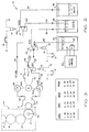
- a portable control console 10 is coupled in fluid communication with an in-line doctor blade apparatus 12 for use in applying a protective and/or decorative liquid coating material to a freshly printed surface in a sheet-fed or web-fed, offset rotary or flexographic printing press.
- the doctor blade coating apparatus 12 is installed in the final press unit of a four color printing press, such as that manufactured by Heidelberger Druckmaschinen AG of the Federal Republic of Germany under its designation Heidelberg Speedmaster 102V.
- the press includes a press frame F which supports the printing components of four substantially identical sheet printing units which can print different color inks onto the sheets S as they are individually and sequentially fed into the press at one end, and which includes a sheet delivery stacker in which the finally printed sheets S are collected and stacked at the opposite end.
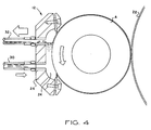
- printing unit 14 is of conventional design, including a plate cylinder 16, a blanket cylinder 18 and an impression cylinder 20.
- the protective or decorative liquid coating material is applied by an auxiliary blanket cylinder 22, which also functions as a transfer/delivery cylinder, which is mounted on the transfer/delivery cylinder drive shaft 23.
- a protective and/or decorative coating is applied by an application roller A to the auxiliary blanket 22, which in turn applies it to the freshly printed sheet.
- the in-line coating apparatus 12 is shown in Figure 1 and Figure 4.
- Liquid coating material L is picked up by the applicator roller A which preferably is an anilox roller having an engraved surface which is designed to pick up a predetermined uniform thickness of liquid material from the doctor reservoir 24, and then uniformly transfer the coating material to the surface of the blanket cylinder 22.
- the doctor reservoir cavity 24 is formed within an elongated doctor blade head 26 having a generally C-shaped cross section with an opening extending longitudinally along one side facing the applicator roller A.
- the reservoir 24 is supplied with liquid coating material from a supply drum 28 through feed and return conduits 30, 32, respectively, which provide for circulation of liquid coating material from the remote drum 28 to circulation control valves within the console 10, and to and from the doctor reservoir 24.
- the remote supply drum 28 along with a clean water supply reservoir 34 and a waste receiving means, for example a dump reservoir 36, are shown diagramatically.
- a waste receiving means for example a dump reservoir 36
- the clean water reservoir 34 and the waste dump reservoir 36 are located within the portable console 10, as shown in Figure 6.
- a feed pump 38 and a return pump 40 are provided for circulating the liquid coating material and cleaning water from the storage reservoirs to the doctor reservoir 24 and return.
- the pumps 38, 40 are peristolic pumps which do not draw air into the circulation line.
- the pumps 38, 40 are driven by an electric drive motor M which is mechanically coupled in concurrent driving relation to the pumps by rotor drive shafts 42A, 42B, respectively.
- the electric motor M is energized ON by a source of electrical current through a single pole, single throw switch S1.
- Two pumps are preferred for adjusting the rate at which liquid material is supplied to and returned from the coater reservoir 22.
- the circulation system of the invention may be operated satisfactorily with only a single pump, either in the feed conduit 30 or in the return conduit 32.
- a single pump 38 is connected in the feed conduit 30, and the coater reservoir 22 is pressurized with liquid material at an internal positive pressure which is greater than atmospheric pressure.
- a single pump 40 is connected in the return conduit 32, and liquid material is supplied to the coater reservoir 22 by suction flow through the feed conduit 30, with the internal pressure of the coater reservoir 24 being maintained at a pressure level less than atmospheric pressure. All three pumping arrangements may be utilized to achieve the advantages and objects of the present invention.
- a set of flow control valves 42, 44 and 46 are interconnected with the feed and return conduits 30, 32, together with a wash water conduit 48, an air inlet port 50 and a drain conduit 52.
- the valves are actuated by electrical solenoids K2, K3 and K4, respectively.
- the control valves 42, 44 and 46 are shown in the de-energized state and the control switches are shown in the OFF position. Upon closure of a control switch, the control valve shuttles to the position indicated by the dashed arrow which provides the appropriate flow path for the function selected.
- the valves 42, 44 and 46 are conventional two position, three-port flow valves, commonly referred to as a three-way valve.
- Control valves 42, 44 are each connected so as to provide a single outlet port with alternative inlet ports.
- the flow control valve 46 is connected so as to have a single inlet port with alternative (switched and unswitched) outlet ports.
- the flow control valve 42 has a first (unswitched) inlet port connected to the feed conduit 30 and a second (switched) inlet port connected to the air inlet port 50.
- the unswitched and switched positions are indicated by solid and dashed arrows, respectively.
- control valve 42 will conduct liquid flow through its outlet port to the inlet of the feed pump 38 when the solenoid K2 is deenergized (switch S2 in the OFF position) and will conduct ambient air through the air inlet port 50 to the input of the feed pump 38 for the purpose of draining the system when the switch S2 is pressed ON and the solenoid K2 is energized.
- the switched position of the control valve 42 is indicated by the dashed arrow.
- the control solenoid 44 has its unswitched inlet port connected to the feed conduit 30 and its switched inlet port connected to the wash water conduit 48.
- the control flow valve 44 will feed liquid coating material from the supply drum 28 to the unswitched inlet port of the first flow control valve 42 when switch S3 is in its OFF position (solenoid K3 de-energized).
- solenoid K3 Upon closure of control switch S3, solenoid K3 is energized ON, and the control valve 44 switches to the position shown by the dashed arrow so that clean wash water may be pumped from the cleaning water reservoir 34 for circulation through the flow lines and doctor reservoir 24.
- the flow control valve 46 is connected to permit liquid material circulation when the control switch S4 is OFF, and PURGE operation when control switch S4 is ON.
- the inlet port of the control switch 46 is connected to the outlet of the return pump 40 for circulating return flow through the conduit 32.
- the control switch S4 is OFF, the flow through the control valve 46 is discharged from the unswitched outlet port through the return conduit 32 into the remote coating storage drum 28.
- the control valve 46 shifts to the position indicated by the dashed arrow, thus delivering its output from the switched outlet port through the drain conduit 52 for dumping into the waste reservoir 36.
- control switch S1 When control switch S1 is actuated, the drive motor M is operated to drive the feed and return pumps 38, 40. Coating liquid is pumped from the remote drum 28 through the circuit provided by the feed conduit 30, the control valve 44 and the control valve 42. Coating liquid is returned from the doctor reservoir 24 by the return pump 40 through the circuit established by the return conduit 32, the control valve 46 and the terminal end portion of the return conduit 32.
- control switch S4 When it becomes necessary to purge liquid material from the doctor reservoir 24, for example at the beginning of a work day, or when contamination is detected during a coating run, control switch S4 is turned ON and coating liquid is circulated through control valve 44, control valve 42, feed pump 38, doctor reservoir 24, return pump 40 and return conduit 32 to the inlet port of the control valve 46. The unused or contaminated coating contents of the doctor reservoir 24 are then dumped through the purge conduit 52 into the waste reservoir 36, and the doctor reservoir 24 is replenished with fresh coating material.
- the doctor reservoir 24 and the circulation conduits 30, 32 may be thoroughly cleaned along with the anilox roller 20 without removing the coater from the press simply by turning control switches S1, S3, and S4 to the ON position, with control switch S2 remaining in the OFF position.
- warm cleaning water is pumped from the water reservoir 34 through the wash inlet port of the control valve 44, through the control valve 42 which is in the de-energized position, through the feed pump 38, doctor reservoir 24 where it is returned through the conduit 32 by the pump 40 to the inlet port of the control valve 46. Since control switch S4 is ON, the mixture of cleaning water and coating material is discharged through its PURGE port where it is dumped into the waste reservoir through the drain conduit 52.
- the cleaning water is heated by a resistance heater H.
- the temperature of the water is sensed by a thermistor T, which is input to a heater control circuit 54.
- the heater control circuit 54 is adjusted to maintain a water temperature within a desired range, for example 100°F - 150°F (37°C - 65°C).
- System DRAIN is performed by pushing control switches S1, S2 and S4 ON with control switch S3 remaining OFF. In that configuration, both pumps 38, 40 are operating, and the control valve 46 is switched to the PURGE position. The status of control valve 44 has no effect in the DRAIN configuration since its output is connected to the non-selected feed input of the control valve 42.
- control switch S2 Upon actuation of control switch S2, the control valve 42 switches to the dashed arrow position, thus permitting air to be pumped through the air inlet port 50 through the feed conduit 30 and into the doctor reservoir 24. The air flow is sufficient to displace residual water out of the flow lines and doctor reservoir. The residual water is dumped through the purge conduit 52 into the waste reservoir 36.
- a simple manual control circuit as shown in Figure 2 may be employed or, alternatively, a cyclic control device as shown in Figure 7, either electromechanical or solid state, may be used to provide completely automatic operation. That is, at the end of a coating run, or at the end of a work day, when it is desired to clean and drain the system, the WASH mode is selected by manually pushing the switches S1, S3 and S4 to the ON position (S2 OFF) and leaving them in the ON position for a predetermined period of time. Next, switches S1, S2 and S4 are pushed ON (S3 OFF), thus initiating the DRAIN mode for a predetermined period of time. Both procedures require operator attention and supervision.
- control switches S1, S2, S3 and S4 are preferably clustered on the operating panel of the console control unit 10.
- the console control unit 10 includes a master power switch 56, a water temperature digital display 58, a heater switch 60 and a pump override switch 62. If the control unit 10 is equipped with a cyclic controller for providing completely automatic sequencing operation, the push buttons which correspond with switches S1, S2, S3 and S4 may instead be designated "PURGE", “COAT”, “WASH” and “DRAIN”, respectively. Other visual indicators, for example a low water warning light 64 and a power ON light 66 are provided for the convenience of the press operator.
- the drive motor M is coupled to the feed pump 38 and the return pump 40 through a gear reducer 68, drive belts 70, 72 and coupling pulleys 76, 78 and 80, 82, respectively.
- both pumps are operated by a single drive motor, with the pumping speed being adjusted appropriately by the gear reducer 66 and the pulley ratios.
- Remote actuation by the press operator of the four push button switches S1, S2, S3 and S4 achieves the primary benefits of the invention which is the elimination of manual cleaning employing rags and the like, and without requiring removal of the coater or coater components from the press and reinstallation thereof.
- an automatic control circuit 100 for example as shown in Figure 7, Figure 12 and Figure 13, it is only necessary for the operator to push a single button to initiate the PURGE mode for a predetermined duty cycle followed automatically by the WASH and DRAIN modes of operation for a predetermined duty cycles. That is, in the automatic operating mode, the operator need only press a single button, and the system cycles automatically from one selected mode to another to system OFF.
- the PURGE operating mode may be engaged manually at any time contamination of the coating liquid is detected.
- Operation of the automatic control circuit 100 is coordinated by first and second servo actuated flow control valves Q1, Q2, and by an automatic controller 102.
- the automatic controller includes push button switches designated “COAT”, “PURGE”, “WASH” and “DRAIN”.
- the automatic controller 102 includes a programmable memory which generates control signals 104, 106, 108 and 110 for controlling the operation of the solenoid K1, the servo drive motor M of control valve Q2, the servo drive motor M of the control valve Q1 and a solenoid K5 which controls a normally open flow valve V5.
- the operating program within the automatic controller 102 produces the appropriate combination of control signals according to the selected operating mode as shown in the instruction table of Figure 9.
- "SW” and “SW” refer to the switched (dashed arrow) and unswitched (solid arrow) positions of servo valves Q1, Q2 respectively.
- servo flow valve Q1 In the PURGE operating mode, servo flow valve Q1 is in the unswitched position as shown by the solid arrow, and the servo flow valve Q2 is in the switched position as shown by the dashed arrow. This permits the flow of coating liquid from the coating reservoir 28 through the pump 38, coater 12, pump 40, for return through the return conduit 32 through the servo control flow valve Q2 into the waste collection reservoir 36.
- both servo control valves Q1, Q2 In the DRAIN operating mode, both servo control valves Q1, Q2 are in the switched positions and the control valve V5 is closed. Upon closure of valve V5, air is admitted through a one-way check valve 112 which is coupled in the flow conduit 48 by a T coupling 114. The one-way check valve 112 is blocked during COAT, PURGE and WASH operations by the reverse pressure differential condition which arises as a result of the positive pressure of water flow through the conduit 48 relative to ambient pressure across the check valve 112.
- the pump apparatus may be operated and the control valves may be sequenced from a referenced operating condition to a subsequent operating condition without any care or attention on the part of the operator and with the operator being required only to initiate the sequence by pressing ON a single push button.
- an automatic control operation may be carried out in connection with the PURGE operating mode followed by the COAT operating mode and in the PURGE operating mode followed by the WASH and DRAIN operating modes.
- Such an automatic control arrangement may be provided by a series of wiper switches coupled to a common shaft which is adapted to turn ON the drive motors and corresponding solenoids in a predetermined sequence corresponding with first and second operating modes. It will be appreciated that the automatic control and sequencing of the valves and pumps is not limited to the use of wiper switches and that such control and sequencing may be carried out by solid state circuitry or even by pneumatic control means.
- cleaning water is circulated through the doctor reservoir 24 which has the effect of simultaneously cleaning the applicator roller A at the same time the reservoir is cleaned.
- the WASH cycle is continued until the wash return lines indicate that all coating material has been removed, thus indicating that all coating liquid has been removed from the doctor reservoir, anilox roller and circulation conduits.
- An auxilliary motor is provided for driving the anilox roller A while the press is stopped, and preferably at a speed sufficient to provide for agitation of the cleaning water within the doctor reservoir.
- the applicator roller being coupled in coating engagement with an auxiliary blanket roller which is installed in the delivery/transfer cylinder position of a printing press.
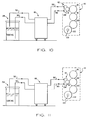
- the coater and circulation system may be used to good advantage with the applicator roller coupled in coating engagement with the plate cylinder 16, as shown in Figure 10, or coupled in coating engagement with the blanket cylinder 18 as shown in Figure 11, with the plate cylinder 16 and blanket cylinder 18 being shown in typical operating positions of an offset printing press.
- the coating circulation and wash-up system described above provides the advantages of the invention as stated. Regardless of whether the assembly is under remote control by manual push buttons as shown in Figure 3, or fully automatic as shown in Figure 8, Figure 12 and Figure 13, the task of removing the coater from the press and cleaning the doctor reservoir with rags has been completely eliminated. Moreover, any hazardous/toxic waste materials are safely contained for disposal, without exposure to the press personnel or to the press. It will be appreciated that the coating circulation and wash-up system of the present invention has universal application not only in presses of new design, but also in presses already in the field which may be retrofitted without making any modification whatsoever to the existing press or coater equipment.
Landscapes
- Coating Apparatus (AREA)
- Inking, Control Or Cleaning Of Printing Machines (AREA)
- Details Or Accessories Of Spraying Plant Or Apparatus (AREA)
Abstract
Description
- This invention relates to sheet-fed, offset rotary printing presses, and in particular to a system for circulating a liquid material such as protective/decorative coating or liquid ink through a coater unit, and including apparatus for automatically purging, washing and draining the coater and circulation system.
- In some offset printing applications, it is desirable that the press be capable of applying a protective and/or decorative coating over all or a portion of the surface of the printed sheets. Such coatings typically are formed of a UV-curable or water-soluble resin applied as a liquid solution or emulsion by an applicator roller over the freshly printed sheets to protect the ink and improve the appearance of the sheets. Use of such coatings is particularly desirable when decorative or protective finishes are required, for example in the production of posters, record jackets, brochures, magazines, folding cartons, labels and the like., Adhesive coatings are sometimes applied to folding cartons, record jackets and the like. In cases where a coating is to be applied, the coating operation is carried out after the final ink printing has been performed, usually by an in-line coater or by a separate coating unit located downstream of the last printing station so that the coating is applied to the sheets after final printing, but before the sheets have reached the sheet delivery stacker.
- When the coater is to remain idle for an extended period between jobs, or at the end of the work day, the coating should be drained from the coating apparatus, and all coater components and flow lines should be thoroughly cleaned, using a solvent or detergent solution and rags. Typically, the supply and return lines must be flushed, the coater must be flushed and hand cleaned, and the coating roller or rollers and reservoir pan must be cleaned manually. It will be appreciated that a substantial amount of press down time is involved during the manual cleaning of the coater components. The manual cleaning task requires the coater to be removed from the press to provide clean-up access to internal components. Moreover, the internal surfaces of the doctor blade cavity are difficult to reach with a cleaning rag, with the result that the reservoir cavity may become contaminated with a sticky coating residue which gradually builds up and may contaminate the coating liquid during subsequent press runs. The time spent in cleaning the coater is non-productive time and therefore there has been a long-felt need for a system to reduce the wash-up time between jobs.
- After extended press runs, ink residue and airborne dirt particles, spray powder and the like sometimes accumulate on the coater, for example on the coating roller and within the coating reservoir. Consequently, it is necessary to remove contaminated coating liquid from the coating reservoir from time to time and to replace it with fresh, clean coating liquid. Such cleaning operations require the press to be shut down for an extended period of time while the coating unit is removed from the press so that the contaminated coating material may be removed and the wettable surfaces cleaned, and then reinstalled on the press.
- The present invention may provide a coater assembly which performs conventional coating operations, and which is self-cleaning and does not require manual effort by press personnel. The coater components may be cleaned and drained using only a cleaning liquid and air while the coater remains attached to the press, and does not require disassembly/removal and reassembly of the coater for manual cleaning by rags, or by a brush within a cleaning sink. Cleaning operations are performed more completely and more thoroughly than could be achieved by the conventional manual method using cleaning rags. The coater assembly is capable of cleaning operation with only water as the cleaning solution, and can he simple to construct and install. The same pumps may operate to circulate the cleaning water, as well as to circulate the, coating liquid, with the supply and return lines, valves and pumps which circulate the coating liquid and water all being thoroughly drained, cleaned and renewed simultaneously with the cleaning of the coater head and anilox roller, thus preventing the progressive build-up of sticky residue which usually occurs in the coating components of such systems.
- The valving, pumping and storage means for handling both the coating liquid and the cleaning water lends itself to simple and easy remote control of circulation valves and pumps. The coater assembly employs two position, three-port control valves to effect different operating modes (PURGE, COAT, WASH, DRAIN) which may be actuated either electrically or pneumatically under the control of simple push button switch circuitry, or under the control of automatic sequencing means.
- It will be appreciated that the wash-up method and apparatus of the present invention is safer to operate as compared with the conventional method of disassembly/removal/reassembly of the coater for manual cleaning with rags. Because it is not necessary to disassemble or remove the coater while performing any of the operating modes, press personnel are not exposed to the cleaning solvents and waste materials. Moreover, misalignment of the coater and incorrect installation problems are completely avoided, including unnecessary exposure of press personnel to contact with rotating machinery during disassembly, removal and reinstallation.
- The foregoing advantages are provided according to the present invention by a coater assembly which includes a pump for circulating liquid coating material through a doctor reservoir during PURGE/replenishing and COAT operations, and for circulating cleaning water and/or air through the doctor reservoir during a WASH cycle or during a DRAIN cycle. According to a preferred aspect of the invention, the valving, pumping and storage of both the coating liquid and cleaning liquid are integrated within a portable console unit which may be remotely located with respect to the press. The various operating modes are coordinated by two position, three-port circulation valves which are actuated by electrical solenoids under the control of simple push button switches. The push button switches may be actuated manually to provide for PURGE, COAT, WASH and DRAIN. Alternatively, the control circuits may be operated by cyclic control means and servo motors for automatic sequencing of the control valves and pump motor from an initial condition, with the actuation of a single push button switch being all that is required to initiate any one of the operating modes for a predetermined duty cycle.
- Operational features and advantages of the present invention will be appreciated by those skilled in the art upon reading the detailed description which follows with reference to the accompanying drawings, wherein:
- Figure 1 is a perspective view showing the coating apparatus of the present invention in combination with an offset printing press and illustrating the fluid path of coating material from a remote console unit to the doctor blade reservoir of the coating apparatus;
- Figure 2 is a simplified schematic diagram of the manual sequencing embodiment of the coating apparatus shown in Figure 1;
- Figure 3 is an instruction table showing the required switch settings for implementing PURGE, COAT, WASH and DRAIN operations;
- Figure 4 is a simplified schematic diagram showing the flow of coating liquid to and from a coating application roller;
- Figure 5 is a simplified schematic diagram showing the flow of coating liquid from a coating liquid supply reservoir through the control console of the present invention to a coating applicator roller;
- Figure 6 is an elevational view, partially in section, of the control console showing the relative positions of pumping components, cleaning water reservoir and waste water reservoir;
- Figure 7 is a top plan view of the control console;
- Figure 8 is a simplified schematic diagram of the automatic sequencing embodiment of the coating apparatus shown in Figure 1;
- Figure 9 is an instruction table showing the operating status of the various control components of the automatic system of Figure 8 for implementing PURGE, COAT, WASH and DRAIN operations;
- Figure 10 is a simplified flow diagram in which the coater apparatus is installed in coating engagement with the plate cylinder of a printing unit;
- Figure 11 is a view similar to Figure 10 in which the coater apparatus is installed in coating engagement with the blanket cylinder of a printing unit;
- Figure 12 is a simplified schematic diagram of an alternative automatic sequencing embodiment of the coating apparatus shown in Figure 1, in which circulation of liquid materials is provided by a single pump in a positive feed arrangement; and,
- Figure 13 is a simplified schematic diagram of an alternative automatic sequencing embodiment of the coating apparatus shown in Figure 1 in which liquid material is circulated by a single pump in a suction flow arrangement.
- In the description which follows, like parts are indicated throughout the specification and drawings with the same reference numerals respectively. The drawings are not necessarily to scale, and the proportions of certain parts have been exaggerated for purposes of clarity.
- Operation of the exemplary embodiments is described with reference to a protective and/or decorative liquid coating material. However, it should be understood that the embodiments of the invention may be used to good advantage in combination with other coating materials, for example liquid adhesives. Moreover, the coating apparatus may also be used for applying ink.
- While water is preferred as a cleaning fluid, it will be understood that other cleaning fluids, including liquid solvents, capable of washing away or dissolving the residual coating material in the reservoir and in the circulation conduits may be used to good advantage. Where a chemical solvent is used, the waste material may be processed and reclaimed or collected for treatment so that it may be safely discharged into a sewer.
- Referring now to Figure 1, a
portable control console 10 is coupled in fluid communication with an in-linedoctor blade apparatus 12 for use in applying a protective and/or decorative liquid coating material to a freshly printed surface in a sheet-fed or web-fed, offset rotary or flexographic printing press. In this instance, the doctorblade coating apparatus 12 is installed in the final press unit of a four color printing press, such as that manufactured by Heidelberger Druckmaschinen AG of the Federal Republic of Germany under its designation Heidelberg Speedmaster 102V. The press includes a press frame F which supports the printing components of four substantially identical sheet printing units which can print different color inks onto the sheets S as they are individually and sequentially fed into the press at one end, and which includes a sheet delivery stacker in which the finally printed sheets S are collected and stacked at the opposite end. - Referring now to Figure 3,
printing unit 14 is of conventional design, including aplate cylinder 16, ablanket cylinder 18 and animpression cylinder 20. The protective or decorative liquid coating material is applied by anauxiliary blanket cylinder 22, which also functions as a transfer/delivery cylinder, which is mounted on the transfer/deliverycylinder drive shaft 23. A protective and/or decorative coating is applied by an application roller A to theauxiliary blanket 22, which in turn applies it to the freshly printed sheet. The in-line coating apparatus 12 is shown in Figure 1 and Figure 4. Liquid coating material L is picked up by the applicator roller A which preferably is an anilox roller having an engraved surface which is designed to pick up a predetermined uniform thickness of liquid material from thedoctor reservoir 24, and then uniformly transfer the coating material to the surface of theblanket cylinder 22. - The
doctor reservoir cavity 24 is formed within an elongateddoctor blade head 26 having a generally C-shaped cross section with an opening extending longitudinally along one side facing the applicator roller A. Thereservoir 24 is supplied with liquid coating material from asupply drum 28 through feed andreturn conduits remote drum 28 to circulation control valves within theconsole 10, and to and from thedoctor reservoir 24. - Referring now to Figure 2, the
remote supply drum 28 along with a cleanwater supply reservoir 34 and a waste receiving means, for example adump reservoir 36, are shown diagramatically. Preferably, theclean water reservoir 34 and thewaste dump reservoir 36 are located within theportable console 10, as shown in Figure 6. - A
feed pump 38 and areturn pump 40 are provided for circulating the liquid coating material and cleaning water from the storage reservoirs to thedoctor reservoir 24 and return. Preferably, thepumps pumps rotor drive shafts - Two pumps, one in the
feed conduit 30 and one in thereturn conduit 32, are preferred for adjusting the rate at which liquid material is supplied to and returned from thecoater reservoir 22. However, it should be understood that the circulation system of the invention may be operated satisfactorily with only a single pump, either in thefeed conduit 30 or in thereturn conduit 32. Referring to Figure 12, asingle pump 38 is connected in thefeed conduit 30, and thecoater reservoir 22 is pressurized with liquid material at an internal positive pressure which is greater than atmospheric pressure. Referring to Figure 13, asingle pump 40 is connected in thereturn conduit 32, and liquid material is supplied to thecoater reservoir 22 by suction flow through thefeed conduit 30, with the internal pressure of thecoater reservoir 24 being maintained at a pressure level less than atmospheric pressure. All three pumping arrangements may be utilized to achieve the advantages and objects of the present invention. - For the purpose of controlling the flow of liquid coating material or cleaning fluid through different flow circulation circuits corresponding with PURGE, COAT, WASH and DRAIN, respectively, a set of
flow control valves conduits wash water conduit 48, anair inlet port 50 and adrain conduit 52. The valves are actuated by electrical solenoids K2, K3 and K4, respectively. Thecontrol valves - The
valves Control valves flow control valve 46 is connected so as to have a single inlet port with alternative (switched and unswitched) outlet ports. Thus, theflow control valve 42 has a first (unswitched) inlet port connected to thefeed conduit 30 and a second (switched) inlet port connected to theair inlet port 50. The unswitched and switched positions are indicated by solid and dashed arrows, respectively. According to this arrangement, thecontrol valve 42 will conduct liquid flow through its outlet port to the inlet of thefeed pump 38 when the solenoid K2 is deenergized (switch S2 in the OFF position) and will conduct ambient air through theair inlet port 50 to the input of thefeed pump 38 for the purpose of draining the system when the switch S2 is pressed ON and the solenoid K2 is energized. The switched position of thecontrol valve 42 is indicated by the dashed arrow. - The
control solenoid 44 has its unswitched inlet port connected to thefeed conduit 30 and its switched inlet port connected to thewash water conduit 48. Thus, thecontrol flow valve 44 will feed liquid coating material from thesupply drum 28 to the unswitched inlet port of the firstflow control valve 42 when switch S3 is in its OFF position (solenoid K3 de-energized). Upon closure of control switch S3, solenoid K3 is energized ON, and thecontrol valve 44 switches to the position shown by the dashed arrow so that clean wash water may be pumped from the cleaningwater reservoir 34 for circulation through the flow lines anddoctor reservoir 24. - The
flow control valve 46 is connected to permit liquid material circulation when the control switch S4 is OFF, and PURGE operation when control switch S4 is ON. The inlet port of thecontrol switch 46 is connected to the outlet of thereturn pump 40 for circulating return flow through theconduit 32. When the control switch S4 is OFF, the flow through thecontrol valve 46 is discharged from the unswitched outlet port through thereturn conduit 32 into the remotecoating storage drum 28. Upon closure of switch S4, thecontrol valve 46 shifts to the position indicated by the dashed arrow, thus delivering its output from the switched outlet port through thedrain conduit 52 for dumping into thewaste reservoir 36. - The various switch combinations required to produce a specific operating mode are indicated in Figure 3. For example, to select the COAT operating mode, it is only necessary to actuate control switch S1 to the ON position, with the control switches S2, S3 and S4 remaining in the OFF position. When control switch S1 is actuated, the drive motor M is operated to drive the feed and return pumps 38, 40. Coating liquid is pumped from the
remote drum 28 through the circuit provided by thefeed conduit 30, thecontrol valve 44 and thecontrol valve 42. Coating liquid is returned from thedoctor reservoir 24 by thereturn pump 40 through the circuit established by thereturn conduit 32, thecontrol valve 46 and the terminal end portion of thereturn conduit 32. - When it becomes necessary to purge liquid material from the
doctor reservoir 24, for example at the beginning of a work day, or when contamination is detected during a coating run, control switch S4 is turned ON and coating liquid is circulated throughcontrol valve 44,control valve 42,feed pump 38,doctor reservoir 24,return pump 40 and returnconduit 32 to the inlet port of thecontrol valve 46. The unused or contaminated coating contents of thedoctor reservoir 24 are then dumped through thepurge conduit 52 into thewaste reservoir 36, and thedoctor reservoir 24 is replenished with fresh coating material. - At the conclusion of a coating run, for example, at the end of the working day, the
doctor reservoir 24 and thecirculation conduits anilox roller 20 without removing the coater from the press simply by turning control switches S1, S3, and S4 to the ON position, with control switch S2 remaining in the OFF position. - During the WASH mode of operation, warm cleaning water is pumped from the
water reservoir 34 through the wash inlet port of thecontrol valve 44, through thecontrol valve 42 which is in the de-energized position, through thefeed pump 38,doctor reservoir 24 where it is returned through theconduit 32 by thepump 40 to the inlet port of thecontrol valve 46. Since control switch S4 is ON, the mixture of cleaning water and coating material is discharged through its PURGE port where it is dumped into the waste reservoir through thedrain conduit 52. - As shown in Figure 2, the cleaning water is heated by a resistance heater H. The temperature of the water is sensed by a thermistor T, which is input to a
heater control circuit 54. Theheater control circuit 54 is adjusted to maintain a water temperature within a desired range, for example 100°F - 150°F (37°C - 65°C). - Typically, after a WASH operation, it is desirable to drain the system. System DRAIN is performed by pushing control switches S1, S2 and S4 ON with control switch S3 remaining OFF. In that configuration, both
pumps control valve 46 is switched to the PURGE position. The status ofcontrol valve 44 has no effect in the DRAIN configuration since its output is connected to the non-selected feed input of thecontrol valve 42. Upon actuation of control switch S2, thecontrol valve 42 switches to the dashed arrow position, thus permitting air to be pumped through theair inlet port 50 through thefeed conduit 30 and into thedoctor reservoir 24. The air flow is sufficient to displace residual water out of the flow lines and doctor reservoir. The residual water is dumped through thepurge conduit 52 into thewaste reservoir 36. - For the purpose of actuating the control switches S1, S2, S3 and S4 in various combinations to establish the operating modes indicated in Figure 3, a simple manual control circuit as shown in Figure 2 may be employed or, alternatively, a cyclic control device as shown in Figure 7, either electromechanical or solid state, may be used to provide completely automatic operation. That is, at the end of a coating run, or at the end of a work day, when it is desired to clean and drain the system, the WASH mode is selected by manually pushing the switches S1, S3 and S4 to the ON position (S2 OFF) and leaving them in the ON position for a predetermined period of time. Next, switches S1, S2 and S4 are pushed ON (S3 OFF), thus initiating the DRAIN mode for a predetermined period of time. Both procedures require operator attention and supervision.
- Referring again to Figure 1, the control switches S1, S2, S3 and S4 are preferably clustered on the operating panel of the
console control unit 10. Theconsole control unit 10 includes amaster power switch 56, a water temperaturedigital display 58, aheater switch 60 and apump override switch 62. If thecontrol unit 10 is equipped with a cyclic controller for providing completely automatic sequencing operation, the push buttons which correspond with switches S1, S2, S3 and S4 may instead be designated "PURGE", "COAT", "WASH" and "DRAIN", respectively. Other visual indicators, for example a low water warning light 64 and a power ONlight 66 are provided for the convenience of the press operator. - Referring now to Figure 5 and Figure 6, the drive motor M is coupled to the
feed pump 38 and thereturn pump 40 through agear reducer 68,drive belts gear reducer 66 and the pulley ratios. Remote actuation by the press operator of the four push button switches S1, S2, S3 and S4 achieves the primary benefits of the invention which is the elimination of manual cleaning employing rags and the like, and without requiring removal of the coater or coater components from the press and reinstallation thereof. - If an
automatic control circuit 100 is used, for example as shown in Figure 7, Figure 12 and Figure 13, it is only necessary for the operator to push a single button to initiate the PURGE mode for a predetermined duty cycle followed automatically by the WASH and DRAIN modes of operation for a predetermined duty cycles. That is, in the automatic operating mode, the operator need only press a single button, and the system cycles automatically from one selected mode to another to system OFF. The PURGE operating mode may be engaged manually at any time contamination of the coating liquid is detected. - Operation of the
automatic control circuit 100, as shown in Figure 8, is coordinated by first and second servo actuated flow control valves Q1, Q2, and by anautomatic controller 102. The automatic controller includes push button switches designated "COAT", "PURGE", "WASH" and "DRAIN". Theautomatic controller 102 includes a programmable memory which generates control signals 104, 106, 108 and 110 for controlling the operation of the solenoid K1, the servo drive motor M of control valve Q2, the servo drive motor M of the control valve Q1 and a solenoid K5 which controls a normally open flow valve V5. The operating program within theautomatic controller 102 produces the appropriate combination of control signals according to the selected operating mode as shown in the instruction table of Figure 9. In Figure 9, "SW" and "SW" refer to the switched (dashed arrow) and unswitched (solid arrow) positions of servo valves Q1, Q2 respectively. - In the PURGE operating mode, servo flow valve Q1 is in the unswitched position as shown by the solid arrow, and the servo flow valve Q2 is in the switched position as shown by the dashed arrow. This permits the flow of coating liquid from the
coating reservoir 28 through thepump 38,coater 12, pump 40, for return through thereturn conduit 32 through the servo control flow valve Q2 into thewaste collection reservoir 36. In the DRAIN operating mode, both servo control valves Q1, Q2 are in the switched positions and the control valve V5 is closed. Upon closure of valve V5, air is admitted through a one-way check valve 112 which is coupled in theflow conduit 48 by aT coupling 114. The one-way check valve 112 is blocked during COAT, PURGE and WASH operations by the reverse pressure differential condition which arises as a result of the positive pressure of water flow through theconduit 48 relative to ambient pressure across thecheck valve 112. - If automatic sequencing means are utilized, as shown in Figure 8, Figure 12 and Figure 13, the pump apparatus may be operated and the control valves may be sequenced from a referenced operating condition to a subsequent operating condition without any care or attention on the part of the operator and with the operator being required only to initiate the sequence by pressing ON a single push button. For example, such an automatic control operation may be carried out in connection with the PURGE operating mode followed by the COAT operating mode and in the PURGE operating mode followed by the WASH and DRAIN operating modes. Such an automatic control arrangement may be provided by a series of wiper switches coupled to a common shaft which is adapted to turn ON the drive motors and corresponding solenoids in a predetermined sequence corresponding with first and second operating modes. It will be appreciated that the automatic control and sequencing of the valves and pumps is not limited to the use of wiper switches and that such control and sequencing may be carried out by solid state circuitry or even by pneumatic control means.
- Such automatic control and sequencing will remove the burden of determining the length of the operating cycle from the press operator, and will permit the press operator to attend to other duties during automatic WASH/DRAIN cycles. Thus, in automatic operation, all the press operator is required to do to initiate a cleaning cycle is to momentarily depress an actuator button which causes the wiper switches to progressively advance from the WASH operating mode to the DRAIN operating mode, and finally turning off the pumps to system OFF upon conclusion of the DRAIN operating mode.
- It is in this state that the automatic controller is left following completion of a coating run or at the end of a day's work. However, if the press operator should desire to refill the coater reservoir with coating liquid, the press operator would press the PURGE switch (S1), then after the PURGE cycle has been completed, press the COAT switch (switch S1), thereby initiating the COAT mode of operation.
- During the WASH mode of operation, cleaning water is circulated through the
doctor reservoir 24 which has the effect of simultaneously cleaning the applicator roller A at the same time the reservoir is cleaned. Preferably, the WASH cycle is continued until the wash return lines indicate that all coating material has been removed, thus indicating that all coating liquid has been removed from the doctor reservoir, anilox roller and circulation conduits. An auxilliary motor is provided for driving the anilox roller A while the press is stopped, and preferably at a speed sufficient to provide for agitation of the cleaning water within the doctor reservoir. - The foregoing preferred embodiment has been described with the applicator roller being coupled in coating engagement with an auxiliary blanket roller which is installed in the delivery/transfer cylinder position of a printing press. However, the coater and circulation system may be used to good advantage with the applicator roller coupled in coating engagement with the
plate cylinder 16, as shown in Figure 10, or coupled in coating engagement with theblanket cylinder 18 as shown in Figure 11, with theplate cylinder 16 andblanket cylinder 18 being shown in typical operating positions of an offset printing press. - It will be apparent that the coating circulation and wash-up system described above provides the advantages of the invention as stated. Regardless of whether the assembly is under remote control by manual push buttons as shown in Figure 3, or fully automatic as shown in Figure 8, Figure 12 and Figure 13, the task of removing the coater from the press and cleaning the doctor reservoir with rags has been completely eliminated. Moreover, any hazardous/toxic waste materials are safely contained for disposal, without exposure to the press personnel or to the press. It will be appreciated that the coating circulation and wash-up system of the present invention has universal application not only in presses of new design, but also in presses already in the field which may be retrofitted without making any modification whatsoever to the existing press or coater equipment.
Claims (21)
- Apparatus (10) for selectively circulating liquid material from a coating liquid supply reservoir (28) or from a cleaning liquid supply reservoir (34) to a coater reservoir (24) and for selectively returning liquid material from the coater reservoir to the coating liquid supply reservoir or to waste receiving means (36), characterized in combination as follows:
a coater (12) adapted for use in combination with a printing press (14), said coater having a reservoir (24) for receiving liquid material from a selected one of said supply reservoirs;
a supply conduit (30) for connecting a selected one of the coating liquid supply reservoir and the cleaning liquid supply reservoir in flow communication with said coater reservoir;
a return conduit (32) for connecting said coater reservoir in flow communication with a selected one of said coating liquid supply reservoir and said waste receiving apparatus;
pump apparatus (40) coupled to at least one of said conduits for feeding liquid material from a selected one of said supply reservoirs to said coater reservoir and for returning liquid material from said coater reservoir through said return conduit;
first valve means (Q1) coupled in flow communication in the supply conduit (30) for selectively feeding liquid material from said coating supply reservoir (28) to said coater reservoir (24) in a first operating mode and for selectively feeding cleaning liquid material from the cleaning liquid supply reservoir (34) to said coater reservoir (24) in a second operating mode; and,
second valve means (Q2) coupled in flow communication in the return conduit (32) for selectively returning liquid material from said coater reservoir (24) to said coating supply reservoir (28) in the first operating mode and for discharging liquid material from said coater reservoir to said waste receiving apparatus (36) in the second operating mode. - Aparatus for selectively circulating liquid material as defined in claim 1, said pump apparatus comprising:
a supply pump (38) coupled in series flow relation with said supply conduit for pumping liquid material from a selected one of said supply reservoirs to said coater reservoir; and,
a return pump (40) coupled in series flow relation with said return conduit for pumping liquid material from said coater reservoir through said return conduit. - Apparatus for selectively circulating liquid material as defined in claim 1, said pump apparatus comprising:
a single pump (38) coupled in series flow relation in said supply conduit (30) for positively pressurizing said coater reservoir (24) with liquid material from a selected one of said supply reservoirs and returning liquid material from said coater reservoir to a selected one of said coating liquid reservoir and said waste handling apparatus by positive pressure flow through said return conduit. - Apparatus for selectively circulating liquid material as defined in any of claims 1 to 3, said pump apparatus comprising:
a single pump (40) coupled in series flow relation in said return conduit (32) for drawing liquid material by suction flow from a selected one of said supply reservoirs through said coater reservoir (24), said liquid material being drawn from said coater reservoir by suction flow and returned through said return conduit to a selected one of said coating liquid reservoir (28) and said waste receiving means (36). - Apparatus for selectively circulating liquid material as defined in any of claims 1 to 4, comprising:
means (102) for actuating said first and second valve means for selectively establishing a flow path for conducting coating liquid from said coating liquid supply reservoir (28) through said coating reservoir (24) and thereafter discharging coating liquid from said coater reservoir into said waste receiving means (36) in a PURGE operating mode. - Apparatus for selectively circulating liquid material as defined in any of claims 1 to 4, comprising:
means (102) for actuating said first and second valve means (Q1, Q2) for selectively establishing a flow path for conducting liquid coating material from said coating liquid supply reservoir (28) through said coater reservoir and return to said liquid coating supply reservoir (28) in a COAT operating mode. - Apparatus for selectively circulating liquid material as defined in any of claims 1 to 4, comprising:
means (102) for actuating said first and second valve means (Q1, Q2) for selectively establishing a flow path for conducting cleaning liquid from said cleaning liquid supply reservoir (34) through said coater reservoir (24) and thereafter discharging liquid material from said coater reservoir into said waste receiving means (36) in a WASH operating mode. - Apparatus for selectively circulating liquid material as defined in any of claims 1 to 4, comprising:
means (102, K5, V5) for actuating said first and second valve means (Q1, Q2) for selectively establishing a flow path for drawing air through said supply conduit (30), said coater reservoir (24) and said return conduit (32) in a DRAIN operating mode. - Apparatus for selectively cirulating liquid material as defined in any of the preceding claims, wherein said pump apparatus (40) is a peristolic pump.
- Apparatus for selectively circulating liquid material as defined in any of the preceding claims having:
heater apparatus thermally coupled in heat transfer relation with said cleaning liquid supply reservoir for maintaining cleaning liquid material within a predetermined temperature range. - Apparatus for selectively circulating liquid material as defined in any of the preceding claims having:
a portable console (10) on which said pump apparatus and said first and second valve means (Q1, Q2) are mounted, wherein the cleaning liquid supply reservoir (34) is contained within said console and said waste receiving means is a dump reservoir (36) separately contained within said console. - Apparatus for selectively circulating liquid material as defined in any of the preceding claims, wherein
said first valve means (Q1) comprises first and second two-position, three port flow control valves (42, 44), said first and second control valves each having switched and unswitched inlet ports and an outlet port, the outlet port of the first control valve (42) being coupled to the inlet port of said pump apparatus, the unswitched inlet port of the first flow control valve (42) being coupled in series with the supply conduit (30) and the switched inlet port (50) of the first flow control valve being coupled to admit ambient air; and,
the outlet port of the second flow control valve (44) being coupled in series flow relation with the unswitched inlet port of the first flow control valve (42), the unswitched inlet port of the second flow control valve (44) being connected in series flow relation with the coating liquid supply reservoir (28), and the switched inlet port of the second flow control valve (44) being coupled in flow communication with the cleaning liquid supply reservoir (34). - Apparatus for selectively circulating liquid material as defined in any of the preceding claims, wherein:
said second valve means (Q2) comprises a two position, three port flow control valve (46), said flow control valve having an inlet port connected to the outlet port of the return pump (40) through the return conduit (32), and having switched and unswitched outlet ports, the unswitched outlet port being coupled in flow communication with the coating liquid supply reservoir (28), and the switched outlet port of said flow control valve being coupled in flow communication with said waste receiving means (36). - Apparatus for selectively circulating liquid material as defined in any of the preceding claims, wherein said coater comprises:
a doctor blade head (26) having an elongated cavity formed therein defining a reservoir (24) for receiving liquid material; and,
an applicator roller (A) having a peripheral surface portion extending into said cavity for wetting contact with liquid material contained therein, and a pair of doctor blades disposed on opposite sides of said cavity and extending the length thereof for engagement against the peripheral surface of said applicator roller in the operative position. - Apparatus for selectively circulating liquid material as defined in any of the preceding claims, wherein
said printing press (14) includes an auxiliary blanket cylinder (22) mounted on a drive shaft (23) in the delivery/transfer cylinder position of said printing press, and said coater (12) is disposed in coating engagement with said auxiliary blanket cylinder. - Apparatus for selectively circulating liquid material as defined in any of the preceding claims, wherein said printing press (14) includes a plate cylinder (16) mounted in the plate cylinder position of said printing press, and said coater (12) is disposed in coating engagement with said plate cylinder.
- Apparatus for selectively circulating liquid material as defined in any of claims 1 to 15, wherein said printing press (14) includes a blanket cylinder (18) mounted in the blanket cylinder position of said printing press, and said coater (12) is disposed in coating engagement with said blanket cylinder.
- Apparatus for selectivly circulating liquid material as defined in any of the preceding claims:
said supply conduit (30), return conduit (32), pump apparatus (38, 40), supply reservoir (28), cleaning liquid supply (34) and waste receiving means (36) being interconnected in a closed loop circulation system, whereby PURGE, COAT, WASH and DRAIN operations may be performed and waste materials may be collected without exposing press personnel and press equipment to contact with the waste materials. - Apparatus for selectively circulating liquid material as defined in any of claims 1 to 10, wherein
a portable console (10) houses the cleaning liquid supply reservoir (34), said waste receiving means (36) is a dump reservoir separately contained within said console, and the supply and return conduits (30, 32) extend externally from said console to said coater (12), whereby said console may be operated remotely from said press (14) and may be moved to a disposal and/or waste treatment station which is remote from said press for further processing of waste material collected in said dump reservoir. - Apparatus for selectively circulating liquid material as defined in any of claims 1 to 11, wherein
said first valve means (Q1) is a two-position, three port flow control valve, said first flow control valve having switched and unswitched inlet ports and an outlet port, the outlet port of the first flow control valve being coupled to the inlet port of said pump apparatus (38), the switched inlet port of the first flow control valve being coupled in flow communication with the cleaning liquid reservoir (34) and the unswitched inlet port of the first flow control valve being coupled in flow communication with the coating liquid reservoir (28); and,
said second valve means (Q2) is a two-position, three port flow control valve, said second flow control valve having an inlet port and switched and unswitched outlet ports, the inlet port of the second flow control valve being connected in series flow relation with the return conduit (30), the unswitched outlet port of the second control valve being coupled in flow communication with the coating reservoir (28), and the switched outlet port of the second flow control valve being coupled in flow communication with said waste receiving means (36). - Apparatus for selectively circulating liquid material as defined in claim 20, wherein
a feed conduit (30) connects the switched inlet port of the first flow control valve (Q1) in flow communication with the cleaning liquid supply reservoir (34);
an ON/OFF flow control valve (V5) is coupled in series flow relation in said feed conduit; and,
a one-way check valve (112) has an inlet port adapted to admit ambient air and has an outlet port coupled in flow communication with the switched inlet port of said first flow control valve (Q1).
Applications Claiming Priority (2)
| Application Number | Priority Date | Filing Date | Title |
|---|---|---|---|
| US08/022,515 US5367982A (en) | 1993-02-25 | 1993-02-25 | Automatic coating circulation and wash-up system for printing presses |
| US22515 | 1993-02-25 |
Publications (2)
| Publication Number | Publication Date |
|---|---|
| EP0612618A2 true EP0612618A2 (en) | 1994-08-31 |
| EP0612618A3 EP0612618A3 (en) | 1995-01-04 |
Family
ID=21809977
Family Applications (1)
| Application Number | Title | Priority Date | Filing Date |
|---|---|---|---|
| EP93304505A Ceased EP0612618A3 (en) | 1993-02-25 | 1993-06-10 | Automatic coating circulation and wash-up system for printing presses. |
Country Status (4)
| Country | Link |
|---|---|
| US (1) | US5367982A (en) |
| EP (1) | EP0612618A3 (en) |
| JP (1) | JPH06246902A (en) |
| CA (1) | CA2097378C (en) |
Cited By (24)
| Publication number | Priority date | Publication date | Assignee | Title |
|---|---|---|---|---|
| DE19546972A1 (en) * | 1995-12-15 | 1997-06-19 | Baldwin Gegenheimer Gmbh | Washing machine of a machine of the graphic industry |
| DE19548535A1 (en) * | 1995-12-22 | 1997-07-03 | Windmoeller & Hoelscher | Method and device for cleaning a doctor blade device for a rinsing inking unit of a rotary printing press |
| EP0876912A1 (en) * | 1997-05-09 | 1998-11-11 | Bryce International, L.L.C. | Inking system for offset printers |
| DE19723830A1 (en) * | 1997-06-06 | 1998-12-10 | Roland Man Druckmasch | Washing device for cleaning cylinders in printing machine |
| EP0924073A1 (en) * | 1997-12-20 | 1999-06-23 | MAN Roland Druckmaschinen AG | Device for metering a coating fluid for print carriers in a printing machine |
| EP0951998A1 (en) * | 1998-04-23 | 1999-10-27 | Umetani Mfg.Co.,Ltd. | Printing machine for corrugated board sheets and method of cleaning ink fountain of the machine |
| EP0970810A1 (en) * | 1998-06-25 | 2000-01-12 | Fischer & Krecke Gmbh & Co. | Method and device for cleaning the ink transport system of a printing press |
| DE19902567A1 (en) * | 1999-01-22 | 2000-08-03 | Technotrans Ag | Device to feed varnish to varnish unit with firmly closed intermediate varnish container and one feed pump |
| WO2001064439A1 (en) * | 2000-02-29 | 2001-09-07 | Koenig & Bauer Aktiengesellschaft | Dampening system and a method for alternately dispensing dampening means or cleaning liquid |
| EP1120252A3 (en) * | 2000-01-28 | 2002-09-18 | HANOSEK, Christian-Peter | Flushing device for a gumming station in a unit for washing, gumming and drying printing plates |
| WO2003091027A1 (en) * | 2002-04-24 | 2003-11-06 | Schiavi S.P.A. | Method for automatically washing the inking circuit in rotary printing presses, and plant for implementing said method |
| WO2004041540A1 (en) | 2002-11-06 | 2004-05-21 | Windmöller & Hölscher Kg | Cleaning of rollers in printing presses |
| WO2004045854A3 (en) * | 2002-11-15 | 2004-10-07 | Graymills Corp | System and method for delivering and flushing ink and other liquids in a printing press |
| EP1433604A3 (en) * | 2002-12-27 | 2006-01-25 | Kabushiki Kaisha Isowa | Apparatus for removing and/or recovering ink, printing machine including such apparatus, and method for supplying and/or recovering ink |
| DE102004058570B3 (en) * | 2004-12-03 | 2006-06-01 | Technotrans Ag | Supply device for washing fluid has injector in supply line from collecting container to spray bar and suction inlet of injector receiving return line from other end of bar |
| DE102007021191A1 (en) | 2007-05-05 | 2008-11-13 | Industrie-Automation Vertriebs-Gmbh | Method and device for dosing a coating fluid in a processing machine |
| US7641448B2 (en) | 2004-03-19 | 2010-01-05 | Tresu Anlaeg A/S | Cleaning an ink chamber of a printing unit |
| DE102008039491A1 (en) | 2008-08-23 | 2010-04-08 | Industrie-Automation Vertriebs-Gmbh | Method for controlling tempering device utilized for tempering e.g. printing ink, involves detecting flow rate of fluid during tempering operation, and bringing tempering agent to external contact from supply line based on detected rate |
| EP1564010A3 (en) * | 2004-02-12 | 2010-05-26 | Canon Kabushiki Kaisha | Liquid applying apparatus and ink jet printing apparatus |
| US20100154706A1 (en) * | 2008-12-19 | 2010-06-24 | Canon Kabushiki Kaisha | Liquid applying apparatus |
| DE102008062741A1 (en) | 2008-12-17 | 2010-07-01 | Industrie-Automation Vertriebs-Gmbh | Method for dosing e.g. printing ink in printing machine to coat printing material with ink, involves evaluating signals of two temperature sensors by controller such that delay time difference between signals is determined |
| CN102774132A (en) * | 2011-05-06 | 2012-11-14 | 海德堡印刷机械股份公司 | System for supplying paint for metering mechanism of printing machine painting device |
| WO2013160499A1 (en) * | 2012-04-26 | 2013-10-31 | Comexi Group Industries, S.A.U. | System for applying a printing liquid or printing adjuvant to a gravure roller |
| WO2017025578A1 (en) * | 2015-08-10 | 2017-02-16 | Windmöller & Hölscher Kg | Ink circuit of an inking unit of a flexographic or gravure printing press |
Families Citing this family (43)
| Publication number | Priority date | Publication date | Assignee | Title |
|---|---|---|---|---|
| US5575211A (en) * | 1994-10-28 | 1996-11-19 | Hycorr Machine Corporation | Washing Arrangement for rotary printer |
| JP2784737B2 (en) * | 1995-03-07 | 1998-08-06 | 井上金属工業株式会社 | Liquid supply / drainage device for roll |
| DE19526574C1 (en) * | 1995-07-20 | 1996-10-17 | Roland Man Druckmasch | Form cylinder and inking roller washing device for printer |
| US5683508A (en) * | 1995-08-25 | 1997-11-04 | Fit Group, Inc. | Coating apparatus and method for dispensing a liquid, and draining and cleaning a coating apparatus |
| US5915302A (en) * | 1996-04-26 | 1999-06-29 | Mitsubishi Jukogyo Kabushiki Kaisha | Printer ink exchange apparatus |
| DE29612159U1 (en) * | 1996-07-12 | 1996-08-29 | MAN Roland Druckmaschinen AG, 63075 Offenbach | Device for quickly creating a production status of a printing unit |
| FR2758493B1 (en) * | 1997-01-17 | 1999-04-02 | Soc Et De Machines Pour Les Ar | DEVICE FOR INKING A WEFT CYLINDER |
| US6210757B1 (en) | 1998-03-23 | 2001-04-03 | Black Clawson Company, Inc. | Pressurized enclosed gravure applicator and method |
| DE19859436B4 (en) * | 1998-12-22 | 2009-12-24 | Heidelberger Druckmaschinen Ag | Digital color dosage |
| DE19860625A1 (en) * | 1998-12-29 | 2000-07-20 | Koenig & Bauer Ag | Pump inking unit |
| US6395088B1 (en) * | 1999-06-30 | 2002-05-28 | Gaston Systems, Inc. | Apparatus for applying foamed coating material to a traveling textile substrate |
| DE19937468A1 (en) * | 1999-08-07 | 2001-03-08 | Roland Man Druckmasch | Device for tempering coating media |
| IT1310460B1 (en) * | 1999-09-01 | 2002-02-18 | Gd Spa | GUMMATOR DEVICE. |
| US6383296B1 (en) | 1999-11-22 | 2002-05-07 | Harris & Bruno Machine Co. | Chambered doctor blade with automatic cleanup and ink replacement |
| US6576059B2 (en) * | 1999-11-22 | 2003-06-10 | Harris & Bruno Company, Inc. | Chambered doctor blade system for water-based and UV-based coatings |
| US6464784B1 (en) * | 1999-12-22 | 2002-10-15 | Eastman Kodak Company | Coating apparatus having a coating, recirculation and cleaning arrangement |
| US6288348B1 (en) | 2000-01-26 | 2001-09-11 | Eaton Corporation | Pneumatic operator for circuit breakers |
| ES2257248T3 (en) * | 2000-10-13 | 2006-08-01 | FISCHER & KRECKE GMBH & CO. | FLEXOGRAPHIC PRINTING MACHINE WITH WASHING DEVICE FOR THE COUNTERPRESSION CYLINDER. |
| US6631682B2 (en) * | 2001-06-13 | 2003-10-14 | Telluckram Maharaj | Non-aqueous cleaning system and method for a printing press recirculation system |
| US7318554B2 (en) * | 2001-10-25 | 2008-01-15 | Langeman Gary D | Third stream automotive color injection |
| DE10246946B4 (en) * | 2001-11-07 | 2013-06-13 | Heidelberger Druckmaschinen Ag | Device for coating substrates in a printing machine |
| DE10209856B4 (en) * | 2002-03-06 | 2007-09-20 | Man Roland Druckmaschinen Ag | Method for controlling the introduction of cleaning fluid |
| CN100400181C (en) * | 2002-12-27 | 2008-07-09 | 本田技研工业株式会社 | Protective layer forming material application system, object to be treated, peelable protective layer, and method for protecting surface of object to be treated |
| JP4355586B2 (en) * | 2004-02-12 | 2009-11-04 | キヤノン株式会社 | Liquid coating apparatus and inkjet recording apparatus |
| US7431771B2 (en) * | 2004-11-12 | 2008-10-07 | Gaston Systems, Inc. | Apparatus and method for applying a foamed composition to a dimensionally unstable traveling substrate |
| US7604344B2 (en) * | 2005-02-09 | 2009-10-20 | Canon Kabushiki Kaisha | Liquid application device and inkjet recording apparatus |
| US7918657B2 (en) * | 2005-04-07 | 2011-04-05 | Bobo Marion H | Head for a peristaltic pump with guide and roller clamp arrangement |
| JP4533274B2 (en) | 2005-08-11 | 2010-09-01 | キヤノン株式会社 | Liquid coating apparatus and inkjet recording apparatus |
| JP4669347B2 (en) * | 2005-08-15 | 2011-04-13 | キヤノン株式会社 | Liquid coating apparatus and inkjet recording apparatus |
| CN101246286B (en) * | 2007-12-26 | 2011-03-30 | 昆山龙腾光电有限公司 | LCD instilling device |
| JP5241003B2 (en) * | 2008-09-05 | 2013-07-17 | 富士フイルム株式会社 | Liquid coating apparatus and method, and image forming apparatus |
| JP2011050823A (en) * | 2009-08-31 | 2011-03-17 | Fujifilm Corp | Liquid applying device and image forming device |
| JP5525784B2 (en) * | 2009-08-31 | 2014-06-18 | 富士フイルム株式会社 | Liquid supply apparatus, liquid application apparatus, and image forming apparatus |
| EP2552599B1 (en) * | 2010-04-02 | 2014-05-21 | Advenira Enterprises, Inc | Roll coater |
| JP5730561B2 (en) * | 2010-12-16 | 2015-06-10 | 富士フイルム株式会社 | Liquid supply device, coating device, and measuring device cleaning method |
| JP5699647B2 (en) * | 2011-02-02 | 2015-04-15 | 株式会社リコー | Image forming apparatus and processing liquid coating apparatus |
| EP2520431B1 (en) * | 2011-05-02 | 2014-03-12 | Heidelberger Druckmaschinen AG | Method for cleaning colour decks in offset printers and offset printer |
| DE102012103851A1 (en) * | 2012-05-02 | 2013-11-21 | Windmöller & Hölscher Kg | Method for cleaning a color system of a rotary printing press and color system |
| US20140216502A1 (en) * | 2013-02-05 | 2014-08-07 | Ecochem Australia Pty Ltd | System and method for automatically cleaning converters |
| JP5701364B1 (en) * | 2013-11-05 | 2015-04-15 | 三菱重工印刷紙工機械株式会社 | Ink cleaning apparatus and ink cleaning method for flexographic printing machine |
| DE102014113217A1 (en) * | 2014-09-12 | 2016-03-17 | Manroland Web Systems Gmbh | Method for cleaning a printing surface |
| GB2532255B (en) * | 2014-11-13 | 2020-04-29 | Itw Ltd | Line cleaner |
| CA3168773C (en) * | 2020-11-10 | 2023-07-25 | Geoffrey LITERSKI | Systems and methods for automatically cleaning converters with heated fluids |
Family Cites Families (23)
| Publication number | Priority date | Publication date | Assignee | Title |
|---|---|---|---|---|
| US3025793A (en) * | 1958-05-07 | 1962-03-20 | Miehle Goss Dexter Inc | Method and apparatus for changing inks in printing press fountains |
| BE788703A (en) * | 1971-09-16 | 1973-01-02 | Rohe Scientific Corp | PERISTALTIC PUMP |
| US3896730A (en) * | 1974-02-22 | 1975-07-29 | Koppers Co Inc | Wash-up system for flexographic printers |
| US4250211A (en) * | 1978-05-31 | 1981-02-10 | Consolidated Papers, Inc. | Paper coating method and apparatus |
| US4534291A (en) * | 1979-12-13 | 1985-08-13 | Sobota James J | Method and apparatus for cleaning printing presses |
| US4369734A (en) * | 1980-03-17 | 1983-01-25 | M.A.N.-Roland Druckmaschinen Aktiengesellschaft | Varnishing assembly in a printing press having self-cleaning feature |
| DE3121821A1 (en) * | 1981-03-07 | 1982-09-16 | Ludwig Schwerdtel GmbH, 8047 Karlsfeld | "DEVICE FOR EMPTYING CYLINDRICAL CONTAINERS CONTAINING IN PARTICULAR PASTEUSE" |
| US4527479A (en) * | 1981-07-31 | 1985-07-09 | Dahlgren Harold P | Ink removal, circulating and distributing system |
| US4395968A (en) * | 1982-03-12 | 1983-08-02 | Paul Wahnschaff | Continuous flow glue pot for glue applicator |
| US4440809A (en) * | 1983-01-17 | 1984-04-03 | Consolidated Papers, Inc. | Method and apparatus for recirculating coating liquid in a paper coating apparatus |
| JPS59142151A (en) * | 1983-02-03 | 1984-08-15 | Komori Printing Mach Co Ltd | Varnish coater for print |
| US4497250A (en) * | 1983-02-08 | 1985-02-05 | Motter Printing Press Co. | Ink Fountain |
| US4526102A (en) * | 1983-10-31 | 1985-07-02 | Molins Machine Company, Inc. | Ink circulation and wash up system for a press |
| JPS60196348A (en) * | 1984-03-17 | 1985-10-04 | Isowa Ind Co | Method for recovery and cleaning of ink in ink transfer mechanish and apparatus for achieving that |
| US4690055A (en) * | 1986-08-28 | 1987-09-01 | Rockwell International Corporation | Keyless inking system for offset lithographic printing press |
| US5005478A (en) * | 1987-12-16 | 1991-04-09 | Precision Engineered Systems Inc. | Blanket wash system with sub-ambient pressure circulation |
| JPH072200Y2 (en) * | 1988-04-18 | 1995-01-25 | 三菱重工業株式会社 | Printer |
| DE3814049A1 (en) * | 1988-04-26 | 1989-11-09 | Koenig & Bauer Ag | METHOD AND DEVICE FOR FLEXO PRINTING |
| FR2648393B2 (en) * | 1988-07-07 | 1991-09-20 | Sarda Jean | IMPROVEMENTS TO CLEANING AND PROCESSING PLANTS FOR THE MAINTENANCE OF PRINTING PRESSES |
| US5003876A (en) * | 1989-02-10 | 1991-04-02 | The Ward Machinery Company | Printing apparatus with dual inking system |
| JPH0434813A (en) * | 1990-05-30 | 1992-02-05 | Hitachi Ltd | high speed circuit breaker |
| AU8512591A (en) * | 1990-09-07 | 1992-03-30 | Nilpeter A/S | A flexographic printing method and apparatus |
| US5176077A (en) * | 1991-08-30 | 1993-01-05 | Howard W. DeMoore | Coating apparatus for sheet-fed, offset rotary printing presses |
-
1993
- 1993-02-25 US US08/022,515 patent/US5367982A/en not_active Expired - Fee Related
- 1993-05-31 CA CA002097378A patent/CA2097378C/en not_active Expired - Fee Related
- 1993-06-10 EP EP93304505A patent/EP0612618A3/en not_active Ceased
- 1993-07-29 JP JP5208259A patent/JPH06246902A/en active Pending
Cited By (34)
| Publication number | Priority date | Publication date | Assignee | Title |
|---|---|---|---|---|
| DE19546972A1 (en) * | 1995-12-15 | 1997-06-19 | Baldwin Gegenheimer Gmbh | Washing machine of a machine of the graphic industry |
| DE19548535A1 (en) * | 1995-12-22 | 1997-07-03 | Windmoeller & Hoelscher | Method and device for cleaning a doctor blade device for a rinsing inking unit of a rotary printing press |
| US5816163A (en) * | 1995-12-22 | 1998-10-06 | Windmoller & Holscher | Process for cleaning a doctor blade device for a rinsable color inking unit of a rotary press |
| DE19548535C2 (en) * | 1995-12-22 | 1999-12-30 | Windmoeller & Hoelscher | Method and device for cleaning a doctor blade device for a rinsing inking unit of a rotary printing press |
| EP0876912A1 (en) * | 1997-05-09 | 1998-11-11 | Bryce International, L.L.C. | Inking system for offset printers |
| DE19723830C2 (en) * | 1997-06-06 | 2003-01-30 | Roland Man Druckmasch | Process for collecting and disposing of used washing liquid from a washing device for a printing press and device for carrying out the process |
| DE19723830A1 (en) * | 1997-06-06 | 1998-12-10 | Roland Man Druckmasch | Washing device for cleaning cylinders in printing machine |
| EP0924073A1 (en) * | 1997-12-20 | 1999-06-23 | MAN Roland Druckmaschinen AG | Device for metering a coating fluid for print carriers in a printing machine |
| EP0951998A1 (en) * | 1998-04-23 | 1999-10-27 | Umetani Mfg.Co.,Ltd. | Printing machine for corrugated board sheets and method of cleaning ink fountain of the machine |
| US6047640A (en) * | 1998-04-23 | 2000-04-11 | Umetani Mfg. Co., Ltd. | Printing machine for corrugated board sheets and method of cleaning ink fountain of the machine |
| EP0970810A1 (en) * | 1998-06-25 | 2000-01-12 | Fischer & Krecke Gmbh & Co. | Method and device for cleaning the ink transport system of a printing press |
| DE19902567A1 (en) * | 1999-01-22 | 2000-08-03 | Technotrans Ag | Device to feed varnish to varnish unit with firmly closed intermediate varnish container and one feed pump |
| EP1120252A3 (en) * | 2000-01-28 | 2002-09-18 | HANOSEK, Christian-Peter | Flushing device for a gumming station in a unit for washing, gumming and drying printing plates |
| WO2001064439A1 (en) * | 2000-02-29 | 2001-09-07 | Koenig & Bauer Aktiengesellschaft | Dampening system and a method for alternately dispensing dampening means or cleaning liquid |
| WO2003091027A1 (en) * | 2002-04-24 | 2003-11-06 | Schiavi S.P.A. | Method for automatically washing the inking circuit in rotary printing presses, and plant for implementing said method |
| WO2004041540A1 (en) | 2002-11-06 | 2004-05-21 | Windmöller & Hölscher Kg | Cleaning of rollers in printing presses |
| WO2004045854A3 (en) * | 2002-11-15 | 2004-10-07 | Graymills Corp | System and method for delivering and flushing ink and other liquids in a printing press |
| US7165494B2 (en) | 2002-11-15 | 2007-01-23 | Graymills Corporation | System and method for delivering and flushing ink and other liquids in a printing press |
| US7165495B2 (en) | 2002-12-27 | 2007-01-23 | Kabushiki Kaisha Isowa | Apparatus for removing and/or recovering ink, printing machine including such apparatus, and method for supplying and/or recovering ink |
| EP1433604A3 (en) * | 2002-12-27 | 2006-01-25 | Kabushiki Kaisha Isowa | Apparatus for removing and/or recovering ink, printing machine including such apparatus, and method for supplying and/or recovering ink |
| EP1564010A3 (en) * | 2004-02-12 | 2010-05-26 | Canon Kabushiki Kaisha | Liquid applying apparatus and ink jet printing apparatus |
| US7641448B2 (en) | 2004-03-19 | 2010-01-05 | Tresu Anlaeg A/S | Cleaning an ink chamber of a printing unit |
| DE102004058570B3 (en) * | 2004-12-03 | 2006-06-01 | Technotrans Ag | Supply device for washing fluid has injector in supply line from collecting container to spray bar and suction inlet of injector receiving return line from other end of bar |
| DE102007021191A1 (en) | 2007-05-05 | 2008-11-13 | Industrie-Automation Vertriebs-Gmbh | Method and device for dosing a coating fluid in a processing machine |
| DE102007021191B4 (en) * | 2007-05-05 | 2010-04-15 | Industrie-Automation Vertriebs-Gmbh | Method and device for dosing a coating fluid in a processing machine |
| US10124365B2 (en) | 2007-05-05 | 2018-11-13 | Industrie-Automation Vertriebs-Gmbh | Method and device for metering a coating liquid in a processing machine |
| DE102008039491A1 (en) | 2008-08-23 | 2010-04-08 | Industrie-Automation Vertriebs-Gmbh | Method for controlling tempering device utilized for tempering e.g. printing ink, involves detecting flow rate of fluid during tempering operation, and bringing tempering agent to external contact from supply line based on detected rate |
| DE102008039491B4 (en) * | 2008-08-23 | 2011-02-24 | Industrie-Automation Vertriebs-Gmbh | Method and device for controlling a temperature control unit for a fluid |
| DE102008062741A1 (en) | 2008-12-17 | 2010-07-01 | Industrie-Automation Vertriebs-Gmbh | Method for dosing e.g. printing ink in printing machine to coat printing material with ink, involves evaluating signals of two temperature sensors by controller such that delay time difference between signals is determined |
| DE102008062741B4 (en) * | 2008-12-17 | 2011-05-12 | Industrie-Automation Vertriebs-Gmbh | Method for dosing a coating fluid in a processing machine |
| US20100154706A1 (en) * | 2008-12-19 | 2010-06-24 | Canon Kabushiki Kaisha | Liquid applying apparatus |
| CN102774132A (en) * | 2011-05-06 | 2012-11-14 | 海德堡印刷机械股份公司 | System for supplying paint for metering mechanism of printing machine painting device |
| WO2013160499A1 (en) * | 2012-04-26 | 2013-10-31 | Comexi Group Industries, S.A.U. | System for applying a printing liquid or printing adjuvant to a gravure roller |
| WO2017025578A1 (en) * | 2015-08-10 | 2017-02-16 | Windmöller & Hölscher Kg | Ink circuit of an inking unit of a flexographic or gravure printing press |
Also Published As
| Publication number | Publication date |
|---|---|
| JPH06246902A (en) | 1994-09-06 |
| EP0612618A3 (en) | 1995-01-04 |
| US5367982A (en) | 1994-11-29 |
| CA2097378A1 (en) | 1994-08-26 |
| CA2097378C (en) | 1997-11-18 |
Similar Documents
| Publication | Publication Date | Title |
|---|---|---|
| US5367982A (en) | Automatic coating circulation and wash-up system for printing presses | |
| EP0382347B1 (en) | Printing apparatus with dual inking system | |
| US4686902A (en) | Automatic blanket wash system | |
| EP0765747B2 (en) | Coating apparatus and method for dispensing a liquid, and draining and cleaning a coating apparatus | |
| US5277111A (en) | Printing cylinder cleaning system | |
| US6576059B2 (en) | Chambered doctor blade system for water-based and UV-based coatings | |
| US5309837A (en) | Method for screen printing of paste | |
| DE19717727B4 (en) | Inking unit for a rotary printing machine | |
| EP0556460B1 (en) | Printing apparatus and method | |
| US4722273A (en) | Washing device for washing a rubber blanket in a rotary offset printing press | |
| JP3153932U (en) | System for coating a substrate with liquid | |
| AU6612598A (en) | A method and a pumping unit for supplying printing ink and cleaning liquid to a printing unit | |
| DE10231598A1 (en) | Product web remoistening apparatus e.g. for paper web, has applicator roller and heating element | |
| GB2332394A (en) | Device for coating printed materials in a printing press | |
| EP0739729B1 (en) | Printer ink exchange apparatus | |
| US6647880B2 (en) | Flexographic printing press with device for washing the back-pressure cylinder | |
| JP3246116U (en) | coating equipment | |
| GB2184982A (en) | Printing machines with multiple liquid supplying trains | |
| CZ2002443A3 (en) | Coating device of a printing machine | |
| US6383296B1 (en) | Chambered doctor blade with automatic cleanup and ink replacement | |
| EP1092534B1 (en) | Cabinet for the delivery of fluids in a printing press | |
| JPH0410423B2 (en) | ||
| JP3421263B2 (en) | Apparatus for metering a coating liquid for a material to be printed in a printing press | |
| EP1695824A2 (en) | Coating unit, especially paint | |
| DE4438043B4 (en) | Process for cleaning a painting system |
Legal Events
| Date | Code | Title | Description |
|---|---|---|---|
| PUAI | Public reference made under article 153(3) epc to a published international application that has entered the european phase |
Free format text: ORIGINAL CODE: 0009012 |
|
| AK | Designated contracting states |
Kind code of ref document: A2 Designated state(s): AT CH DE DK FR GB IT LI SE |
|
| PUAL | Search report despatched |
Free format text: ORIGINAL CODE: 0009013 |
|
| AK | Designated contracting states |
Kind code of ref document: A3 Designated state(s): AT CH DE DK FR GB IT LI SE |
|
| 17P | Request for examination filed |
Effective date: 19950515 |
|
| 17Q | First examination report despatched |
Effective date: 19960621 |
|
| GRAG | Despatch of communication of intention to grant |
Free format text: ORIGINAL CODE: EPIDOS AGRA |
|
| STAA | Information on the status of an ep patent application or granted ep patent |
Free format text: STATUS: THE APPLICATION HAS BEEN REFUSED |
|
| 18R | Application refused |
Effective date: 19990307 |