EP0612542A1 - In drei Richtungen periodische Bewegungen reproduzierende Plattform, mit einer bevorzugten Richtung - Google Patents
In drei Richtungen periodische Bewegungen reproduzierende Plattform, mit einer bevorzugten Richtung Download PDFInfo
- Publication number
- EP0612542A1 EP0612542A1 EP94400405A EP94400405A EP0612542A1 EP 0612542 A1 EP0612542 A1 EP 0612542A1 EP 94400405 A EP94400405 A EP 94400405A EP 94400405 A EP94400405 A EP 94400405A EP 0612542 A1 EP0612542 A1 EP 0612542A1
- Authority
- EP
- European Patent Office
- Prior art keywords
- crank
- platform
- platform according
- base
- connecting rod
- Prior art date
- Legal status (The legal status is an assumption and is not a legal conclusion. Google has not performed a legal analysis and makes no representation as to the accuracy of the status listed.)
- Granted
Links
Images

Classifications
-
- A—HUMAN NECESSITIES
- A63—SPORTS; GAMES; AMUSEMENTS
- A63B—APPARATUS FOR PHYSICAL TRAINING, GYMNASTICS, SWIMMING, CLIMBING, OR FENCING; BALL GAMES; TRAINING EQUIPMENT
- A63B69/00—Training appliances or apparatus for special sports
- A63B69/04—Training appliances or apparatus for special sports simulating the movement of horses
-
- A—HUMAN NECESSITIES
- A63—SPORTS; GAMES; AMUSEMENTS
- A63G—MERRY-GO-ROUNDS; SWINGS; ROCKING-HORSES; CHUTES; SWITCHBACKS; SIMILAR DEVICES FOR PUBLIC AMUSEMENT
- A63G19/00—Toy animals for riding
- A63G19/20—Toy animals for riding motor-driven
Definitions
- Numerous mobiles such as planes, boats or even horses whose movement takes place essentially in a preferred direction are, moreover, driven by periodic movements along the three axes: longitudinal, transverse and vertical.
- the object of the present invention is to produce a mobile platform reproducing periodic movements along the three axes with a preferred direction, this platform being set in motion by extremely simple mechanical means and therefore being inexpensive to manufacture.
- the invention provides a mobile platform intended to reproduce periodic movements along the three axes (longitudinal, transverse, vertical) with a preferred direction, said platform being carried by a base on the one hand, at one end (called “rear”) by means of at least one foot coupled to a crank and on the other hand, at the other end (called “front”) by connecting rods hinged to said base, characterized in that said crank is carried by a support connected to the base by a foot which can be moved laterally so that the crank is located either in a vertical plane comprising the preferred direction, or in an oblique plane on one side or the other with respect to said vertical plane, and in that the two front feet are each articulated on a substantially vertical connecting rod, each connecting rod being articulated directly or indirectly at its lower end on the base.
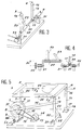
- the machine is constituted by a base 1 which is preferably rectangular.
- This base supports a platform 2 by means of three feet 3, 4 and 5.
- the foot 3 which by convention will be called the rear foot, is connected by a hinge 6 to a crank 7 which can be constituted by a simple arm, as indicated in dotted lines, or by a disc, as shown in solid lines .
- This crank 7 is mounted for rotation on an axis 8 carried by a support 9 resting on the base 1.
- the foot 9a of the support 9 can be moved in one direction or the other along the line 10.
- the support 9 and the crank 7 are arranged in a vertical plane which includes the rear leg 3.
- the support 9 and the crank 7 are placed in an oblique plane, bent to the right or left.
- this position corresponds to the preferred direction XX of the movement of the platform 2.
- the means by which the foot 9a is placed in the desired position are not described because they are not part of the invention and are within the scope of the skilled person. They can be constituted by a slide with screws blocking, by a rack, by an endless screw or by a jack.
- the modification of the position of the foot 9a of the support 9 can be carried out as an adjustment before the machine is started up or can be made during the operation by means of a remote control.
- the shaft 8 is provided with a pulley 11 connected by a belt 12 to the pulley 13 of a motor 14 which is of variable speed and the direction of which can be reversed.
- This motor 14 is provided with control means which make it possible to rotate it in one direction or the other, and to vary its speed of rotation, that is to say the number of revolutions per minute. Means can also be made available for varying the speed cyclically during the execution of each turn.
- One of the front feet, the left foot 4 in the example shown, is articulated to a connecting rod 15, substantially vertical, by means of a joint 16 located at the upper part of the connecting rod 15.
- the connecting rod is directly articulated at its lower part on the base by an articulation 17 linked to a support 18 which is fixed to the base 1.
- the other front foot, the right foot 5 in the example shown, is articulated by an articulation 19 to a connecting rod 20, substantially vertical.
- the connecting rod 19 is directly articulated on the base while being pivotally mounted on an axis 21.
- This axis 21 is horizontal and perpendicular or practically perpendicular to the preferred direction XX.
- the connecting rod 20 is triangulated by means of a horizontal arm 22 and a stay 23.
- the position of the foot 5 on the platform 2 can be changed in the direction indicated by the line 24 in one direction or the other as indicated by the double arrow f2.
- the means allowing these displacements are analogous to those mentioned about the movement of the foot 9a of the support 9.
- the platform is rectangular and has a seat 25 which is located on the median longitudinal axis XX of the platform 2.
- This seat 25 can be moved in one direction or the other, in the direction XX as indicated by the double arrow f3. Again, the means for these movements are similar to those mentioned for the support 9 and the foot 5.
- the crank is in a vertical plane and if the line connecting the feet 5 and 4 is perpendicular to the direction XX, the foot 3 is animated by a rotary movement in a vertical plane and the feet 4 and 5 each describe an arc de-circle in a vertical plane.
- the seat 25 is therefore driven in a forward and backward movement in the direction XX, as well as a pitching movement (up and down). It is understood that, the more the seat 25 is at the front, the greater the displacement due to pitching, while the more the seat is at the rear, the less this movement.
- the line which connects the feet 4 and 5 is no longer perpendicular to the direction XX and to the various movements previously described will overlap a movement of roll.
- the disc 7 can be replaced by an arm of variable length.
- the joint 6 in a window 26 formed in the disc 7 asymmetrically, this joint being able to slide freely in said window and coming to abut against one or the other of the ends of this window 26 according to the direction of rotation of the disc 7.
- the invention makes it possible, among other things, to simulate the gaits of a horse (tread, trot, gallop and jump).
- the invention is not limited to this particular case and the seat 25 can be arranged in the opposite direction and in this case the rear leg becomes front and vice versa.
- joints 6, 16, 17 and 19 are capable of ensuring movements in all directions. They can therefore be formed either by pins mounted to play in their bearings, or by rubber pads like silentbloc, or by ball joints or cardan joints.
- the foot 3 that is to say to have two parallel feet which are connected to the same crank or to a double crank.
- Such an arrangement then eliminates any possibility of rolling movement (longitudinal axis) but makes the connection between the platform and the crank more solid. Still with the aim of making the machine more solid, the two connecting rods 15 and 20 can be braced.
- the connecting rods 15 and 20 on which the front legs 4 and 5 of the platform are articulated are indirectly articulated on the base, being carried by a spindle 30 in two bearings 31.
- the shaft 30 is bent so that the lower ends of said connecting rods are driven by a movement of amplitude R.
- the shaft 31 is rotated by the motor 14 or by a second motor, via a pulley 33 which it carries.
- This embodiment makes it possible to perform pitch movements independently of the position of the support 9 of the rear foot.
- the variant embodiment of FIG. 4 makes it possible to carry out roll movements at the same time as pitch movements independently of the position of the support 9, of the rear foot, by phase differentiation.
- the shaft carrying the lower ends of the connecting rods 15 and 20 is such that it has a first portion 35 carrying the connecting rod 20 describing a cylinder of radius R1, and a second portion 34 carrying the connecting rod 15 describing a cylinder of radius R2, different from R1.
- FIG. 5 also shows an alternative embodiment of the mobile platform according to the invention.
- the rear foot 3 is articulated on the platform 2 by means of a ball joint 35, while the ball joint 6 located in the variant according to FIG. 1 between the foot 3 and the crank 7 is replaced by a simple articulation.
- a second crank 37 which may, as previously, be constituted by a simple arm or by a disc is arranged around the axis 8.
- a connecting rod 36 is disposed between this crank 37 and the ball joint 19 connecting the front leg 5 to the connecting rod 20, so as to impart to the connecting rod 20 oscillating movements.
Landscapes
- Health & Medical Sciences (AREA)
- General Health & Medical Sciences (AREA)
- Physical Education & Sports Medicine (AREA)
- Toys (AREA)
- Transmission Devices (AREA)
Applications Claiming Priority (2)
| Application Number | Priority Date | Filing Date | Title |
|---|---|---|---|
| FR9302224 | 1993-02-26 | ||
| FR9302224A FR2702029B1 (fr) | 1993-02-26 | 1993-02-26 | Plate-forme reproduisant des mouvements périodiques selon les trois axes avec une direction privilégiée. |
Publications (2)
| Publication Number | Publication Date |
|---|---|
| EP0612542A1 true EP0612542A1 (de) | 1994-08-31 |
| EP0612542B1 EP0612542B1 (de) | 1995-12-06 |
Family
ID=9444456
Family Applications (1)
| Application Number | Title | Priority Date | Filing Date |
|---|---|---|---|
| EP19940400405 Expired - Lifetime EP0612542B1 (de) | 1993-02-26 | 1994-02-25 | In drei Richtungen periodische Bewegungen reproduzierende Plattform, mit einer bevorzugten Richtung |
Country Status (3)
| Country | Link |
|---|---|
| EP (1) | EP0612542B1 (de) |
| DE (1) | DE69400035T2 (de) |
| FR (1) | FR2702029B1 (de) |
Cited By (5)
| Publication number | Priority date | Publication date | Assignee | Title |
|---|---|---|---|---|
| WO1996022140A1 (de) * | 1995-01-21 | 1996-07-25 | Emt Elektro-Mobiltechnik Gmbh | Mobiles unterhaltungsgerät |
| WO1997029815A1 (de) * | 1996-02-14 | 1997-08-21 | Dirk Rothhaupt | Vorrichtung zum training der rückenmuskulatur durch übertragung von schwingungen auf einen sitzenden probanden |
| EP1291041A1 (de) * | 2000-06-07 | 2003-03-12 | Matsushita Electric Works, Ltd. | Vorrichtung zum Trainieren des Gleichgewichts |
| EP1123025B1 (de) * | 1998-10-19 | 2004-06-23 | Gisela Schon | Sitz |
| GB2420724A (en) * | 2004-12-06 | 2006-06-07 | Racewood Ltd | Horse simulator |
Citations (4)
| Publication number | Priority date | Publication date | Assignee | Title |
|---|---|---|---|---|
| US3432164A (en) * | 1967-02-14 | 1969-03-11 | Hugh A Deeks | Exercising machine |
| GB1165833A (en) * | 1967-05-30 | 1969-10-01 | R G Mitchell Sales Ltd | Mechanism for Child's Ride |
| EP0407158A1 (de) * | 1989-07-03 | 1991-01-09 | Charles Sean Collins | Trainingspferd |
| FR2670390A1 (fr) * | 1990-12-14 | 1992-06-19 | Jouffroy Jean Louis | Procede de simulation des sensations dues aux mouvements d'un cheval. |
-
1993
- 1993-02-26 FR FR9302224A patent/FR2702029B1/fr not_active Expired - Fee Related
-
1994
- 1994-02-25 DE DE1994600035 patent/DE69400035T2/de not_active Expired - Fee Related
- 1994-02-25 EP EP19940400405 patent/EP0612542B1/de not_active Expired - Lifetime
Patent Citations (4)
| Publication number | Priority date | Publication date | Assignee | Title |
|---|---|---|---|---|
| US3432164A (en) * | 1967-02-14 | 1969-03-11 | Hugh A Deeks | Exercising machine |
| GB1165833A (en) * | 1967-05-30 | 1969-10-01 | R G Mitchell Sales Ltd | Mechanism for Child's Ride |
| EP0407158A1 (de) * | 1989-07-03 | 1991-01-09 | Charles Sean Collins | Trainingspferd |
| FR2670390A1 (fr) * | 1990-12-14 | 1992-06-19 | Jouffroy Jean Louis | Procede de simulation des sensations dues aux mouvements d'un cheval. |
Cited By (10)
| Publication number | Priority date | Publication date | Assignee | Title |
|---|---|---|---|---|
| WO1996022140A1 (de) * | 1995-01-21 | 1996-07-25 | Emt Elektro-Mobiltechnik Gmbh | Mobiles unterhaltungsgerät |
| WO1997029815A1 (de) * | 1996-02-14 | 1997-08-21 | Dirk Rothhaupt | Vorrichtung zum training der rückenmuskulatur durch übertragung von schwingungen auf einen sitzenden probanden |
| AU717596B2 (en) * | 1996-02-14 | 2000-03-30 | Christoph Ann | Device for training the back muscles by the transmission of oscillations to a sitting test subject |
| KR100298982B1 (ko) * | 1996-02-14 | 2002-09-17 | 더크 로스하우프트 | 앉아있는피시험물에의진동전달을통한허리근육단련장치 |
| EP1123025B1 (de) * | 1998-10-19 | 2004-06-23 | Gisela Schon | Sitz |
| EP1291041A1 (de) * | 2000-06-07 | 2003-03-12 | Matsushita Electric Works, Ltd. | Vorrichtung zum Trainieren des Gleichgewichts |
| EP1291041B1 (de) * | 2000-06-07 | 2006-08-16 | Matsushita Electric Works, Ltd. | Vorrichtung zum trainieren des gleichgewichts |
| GB2420724A (en) * | 2004-12-06 | 2006-06-07 | Racewood Ltd | Horse simulator |
| GB2420724B (en) * | 2004-12-06 | 2009-09-23 | Racewood Ltd | Horse simulator |
| US7749088B2 (en) | 2004-12-06 | 2010-07-06 | Racewood Limited | Horse simulator |
Also Published As
| Publication number | Publication date |
|---|---|
| EP0612542B1 (de) | 1995-12-06 |
| DE69400035T2 (de) | 1996-09-05 |
| FR2702029A1 (fr) | 1994-09-02 |
| DE69400035D1 (de) | 1996-01-18 |
| FR2702029B1 (fr) | 1995-05-12 |
Similar Documents
| Publication | Publication Date | Title |
|---|---|---|
| EP0946843B1 (de) | Modular einrichtung zur lastbewegung mit mindestens drei freiheitsgraden | |
| CA2739233C (fr) | Dispositif de mobilisation corporelle et utilisation d'un tel dispositif | |
| FR2609638A1 (fr) | Plancher d'entrainement | |
| CH650142A5 (fr) | Fauteuil roulant motorise omnidirectionnel. | |
| CA2622958A1 (fr) | Procede et dispositif de pedalage | |
| FR2512768A1 (fr) | Systeme de suspension de la roue pour motocycle comportant un mecanisme d'amortissement entre un organe stable et un organe oscillant | |
| FR2860713A1 (fr) | Attelle de mobilisation passive de l'articulation de la cheville | |
| WO2017064379A1 (fr) | Mecanisme equilibre pour economie d'energie, machine tournante et procede de mise en oeuvre | |
| FR2935129A1 (fr) | Pedalier compact | |
| EP0612542B1 (de) | In drei Richtungen periodische Bewegungen reproduzierende Plattform, mit einer bevorzugten Richtung | |
| FR2641722A1 (fr) | Dispositif pour l'entrainement d'une broche porte-outil | |
| EP0520872A1 (de) | Vibrationssimulator für Luftschraubenrotor eines Hubschraubers | |
| FR2826924A1 (fr) | Systeme de commande, systeme directionnel pour vehicule leger et tricycle equipe d'un tel systeme | |
| EP0491613B1 (de) | Handhabungsgerät zum Bewegen eines Gegenstandes in Raum, z.B. parallel mit sichselbst | |
| FR2693280A1 (fr) | Dispositif mobile de déplacement et de positionnement d'un ou de plusieurs appareils optiques. | |
| FR2573407A1 (fr) | Plate-forme de travail mobile, notamment pour l'execution de controle et de travaux sous les ponts | |
| FR2539346A1 (fr) | Dispositif manipulateur automatique articule notamment pour le soudage a l'arc | |
| FR2527945A1 (fr) | Machine a secouer | |
| FR2493948A1 (fr) | Variateur impulsionnel | |
| FR2541603A1 (fr) | Appareil a cintrer | |
| FR2666746A1 (fr) | Appareil de gymnastique pour le travail musculaire en endurance. | |
| FR2913659A1 (fr) | Velo pourvu d'une suspension motrice | |
| EP0687527A1 (de) | Schleifkopf mit oszillierenden Schleifklötzen für die Flächenbearbeitung von Stein | |
| FR2686564A1 (fr) | Vehicule publicitaire assurant son deplacement en l'absence de roues. | |
| JP3918094B2 (ja) | 車椅子装着型無限軌道動力装置 |
Legal Events
| Date | Code | Title | Description |
|---|---|---|---|
| PUAI | Public reference made under article 153(3) epc to a published international application that has entered the european phase |
Free format text: ORIGINAL CODE: 0009012 |
|
| AK | Designated contracting states |
Kind code of ref document: A1 Designated state(s): DE ES FR GB IT |
|
| 17P | Request for examination filed |
Effective date: 19941228 |
|
| 17Q | First examination report despatched |
Effective date: 19950522 |
|
| GRAA | (expected) grant |
Free format text: ORIGINAL CODE: 0009210 |
|
| AK | Designated contracting states |
Kind code of ref document: B1 Designated state(s): DE ES FR GB IT |
|
| PG25 | Lapsed in a contracting state [announced via postgrant information from national office to epo] |
Ref country code: IT Free format text: LAPSE BECAUSE OF FAILURE TO SUBMIT A TRANSLATION OF THE DESCRIPTION OR TO PAY THE FEE WITHIN THE PRE;WARNING: LAPSES OF ITALIAN PATENTS WITH EFFECTIVE DATE BEFORE 2007 MAY HAVE OCCURRED AT ANY TIME BEFORE 2007. THE CORRECT EFFECTIVE DATE MAY BE DIFFERENT FROM THE ONE RECORDED.SCRIBED TIME-LIMIT Effective date: 19951206 Ref country code: ES Free format text: THE PATENT HAS BEEN ANNULLED BY A DECISION OF A NATIONAL AUTHORITY Effective date: 19951206 |
|
| REF | Corresponds to: |
Ref document number: 69400035 Country of ref document: DE Date of ref document: 19960118 |
|
| GBT | Gb: translation of ep patent filed (gb section 77(6)(a)/1977) |
Effective date: 19960312 |
|
| PLBE | No opposition filed within time limit |
Free format text: ORIGINAL CODE: 0009261 |
|
| STAA | Information on the status of an ep patent application or granted ep patent |
Free format text: STATUS: NO OPPOSITION FILED WITHIN TIME LIMIT |
|
| 26N | No opposition filed | ||
| REG | Reference to a national code |
Ref country code: FR Ref legal event code: TP |
|
| REG | Reference to a national code |
Ref country code: GB Ref legal event code: IF02 |
|
| PGFP | Annual fee paid to national office [announced via postgrant information from national office to epo] |
Ref country code: GB Payment date: 20020227 Year of fee payment: 9 |
|
| PGFP | Annual fee paid to national office [announced via postgrant information from national office to epo] |
Ref country code: DE Payment date: 20020314 Year of fee payment: 9 |
|
| PG25 | Lapsed in a contracting state [announced via postgrant information from national office to epo] |
Ref country code: GB Free format text: LAPSE BECAUSE OF NON-PAYMENT OF DUE FEES Effective date: 20030225 |
|
| PGFP | Annual fee paid to national office [announced via postgrant information from national office to epo] |
Ref country code: FR Payment date: 20030228 Year of fee payment: 10 |
|
| PG25 | Lapsed in a contracting state [announced via postgrant information from national office to epo] |
Ref country code: DE Free format text: LAPSE BECAUSE OF NON-PAYMENT OF DUE FEES Effective date: 20030902 |
|
| GBPC | Gb: european patent ceased through non-payment of renewal fee | ||
| PG25 | Lapsed in a contracting state [announced via postgrant information from national office to epo] |
Ref country code: FR Free format text: LAPSE BECAUSE OF NON-PAYMENT OF DUE FEES Effective date: 20041029 |
|
| REG | Reference to a national code |
Ref country code: FR Ref legal event code: ST |