EP0611672A2 - Glazing with profile frame, in particular vehicle glazing - Google Patents
Glazing with profile frame, in particular vehicle glazing Download PDFInfo
- Publication number
- EP0611672A2 EP0611672A2 EP94105771A EP94105771A EP0611672A2 EP 0611672 A2 EP0611672 A2 EP 0611672A2 EP 94105771 A EP94105771 A EP 94105771A EP 94105771 A EP94105771 A EP 94105771A EP 0611672 A2 EP0611672 A2 EP 0611672A2
- Authority
- EP
- European Patent Office
- Prior art keywords
- glazing
- lip
- frame
- opaque layer
- edge
- Prior art date
- Legal status (The legal status is an assumption and is not a legal conclusion. Google has not performed a legal analysis and makes no representation as to the accuracy of the status listed.)
- Granted
Links
- 239000011324 bead Substances 0.000 claims abstract description 10
- 230000001681 protective effect Effects 0.000 claims abstract description 10
- 239000002184 metal Substances 0.000 claims abstract description 5
- 239000011521 glass Substances 0.000 claims description 17
- 239000003292 glue Substances 0.000 claims description 9
- 229920001971 elastomer Polymers 0.000 claims description 4
- 239000000806 elastomer Substances 0.000 claims description 4
- 239000000853 adhesive Substances 0.000 abstract description 12
- 230000001070 adhesive effect Effects 0.000 abstract description 12
- 238000001125 extrusion Methods 0.000 description 22
- 229920000642 polymer Polymers 0.000 description 13
- 230000007704 transition Effects 0.000 description 10
- 238000003825 pressing Methods 0.000 description 8
- 238000004519 manufacturing process Methods 0.000 description 7
- 239000000463 material Substances 0.000 description 7
- 238000000034 method Methods 0.000 description 7
- 239000010408 film Substances 0.000 description 6
- 238000006116 polymerization reaction Methods 0.000 description 6
- 230000008569 process Effects 0.000 description 4
- 239000004698 Polyethylene Substances 0.000 description 2
- 238000004026 adhesive bonding Methods 0.000 description 2
- 238000006243 chemical reaction Methods 0.000 description 2
- 238000009434 installation Methods 0.000 description 2
- 230000002093 peripheral effect Effects 0.000 description 2
- 229920000728 polyester Polymers 0.000 description 2
- -1 polyethylene Polymers 0.000 description 2
- 229920000573 polyethylene Polymers 0.000 description 2
- 229920002635 polyurethane Polymers 0.000 description 2
- 239000004814 polyurethane Substances 0.000 description 2
- 230000037452 priming Effects 0.000 description 2
- XLYOFNOQVPJJNP-UHFFFAOYSA-N water Substances O XLYOFNOQVPJJNP-UHFFFAOYSA-N 0.000 description 2
- 238000004140 cleaning Methods 0.000 description 1
- 210000003298 dental enamel Anatomy 0.000 description 1
- 238000000151 deposition Methods 0.000 description 1
- 238000009826 distribution Methods 0.000 description 1
- 239000012530 fluid Substances 0.000 description 1
- 235000011837 pasties Nutrition 0.000 description 1
- 230000035699 permeability Effects 0.000 description 1
- 239000002985 plastic film Substances 0.000 description 1
- 229920006255 plastic film Polymers 0.000 description 1
- 239000002861 polymer material Substances 0.000 description 1
- 230000000379 polymerizing effect Effects 0.000 description 1
- 238000005086 pumping Methods 0.000 description 1
- 239000010409 thin film Substances 0.000 description 1
- 238000003466 welding Methods 0.000 description 1
Images


Classifications
-
- B—PERFORMING OPERATIONS; TRANSPORTING
- B29—WORKING OF PLASTICS; WORKING OF SUBSTANCES IN A PLASTIC STATE IN GENERAL
- B29D—PRODUCING PARTICULAR ARTICLES FROM PLASTICS OR FROM SUBSTANCES IN A PLASTIC STATE
- B29D99/00—Subject matter not provided for in other groups of this subclass
- B29D99/0053—Producing sealings
-
- B—PERFORMING OPERATIONS; TRANSPORTING
- B29—WORKING OF PLASTICS; WORKING OF SUBSTANCES IN A PLASTIC STATE IN GENERAL
- B29C—SHAPING OR JOINING OF PLASTICS; SHAPING OF MATERIAL IN A PLASTIC STATE, NOT OTHERWISE PROVIDED FOR; AFTER-TREATMENT OF THE SHAPED PRODUCTS, e.g. REPAIRING
- B29C43/00—Compression moulding, i.e. applying external pressure to flow the moulding material; Apparatus therefor
- B29C43/02—Compression moulding, i.e. applying external pressure to flow the moulding material; Apparatus therefor of articles of definite length, i.e. discrete articles
- B29C43/20—Making multilayered or multicoloured articles
- B29C43/203—Making multilayered articles
- B29C43/206—Making multilayered articles by pressing the material between two preformed layers, e.g. deformable layers
-
- B—PERFORMING OPERATIONS; TRANSPORTING
- B29—WORKING OF PLASTICS; WORKING OF SUBSTANCES IN A PLASTIC STATE IN GENERAL
- B29C—SHAPING OR JOINING OF PLASTICS; SHAPING OF MATERIAL IN A PLASTIC STATE, NOT OTHERWISE PROVIDED FOR; AFTER-TREATMENT OF THE SHAPED PRODUCTS, e.g. REPAIRING
- B29C48/00—Extrusion moulding, i.e. expressing the moulding material through a die or nozzle which imparts the desired form; Apparatus therefor
- B29C48/15—Extrusion moulding, i.e. expressing the moulding material through a die or nozzle which imparts the desired form; Apparatus therefor incorporating preformed parts or layers, e.g. extrusion moulding around inserts
- B29C48/154—Coating solid articles, i.e. non-hollow articles
- B29C48/155—Partial coating thereof
-
- B—PERFORMING OPERATIONS; TRANSPORTING
- B29—WORKING OF PLASTICS; WORKING OF SUBSTANCES IN A PLASTIC STATE IN GENERAL
- B29C—SHAPING OR JOINING OF PLASTICS; SHAPING OF MATERIAL IN A PLASTIC STATE, NOT OTHERWISE PROVIDED FOR; AFTER-TREATMENT OF THE SHAPED PRODUCTS, e.g. REPAIRING
- B29C53/00—Shaping by bending, folding, twisting, straightening or flattening; Apparatus therefor
- B29C53/16—Straightening or flattening
-
- B—PERFORMING OPERATIONS; TRANSPORTING
- B29—WORKING OF PLASTICS; WORKING OF SUBSTANCES IN A PLASTIC STATE IN GENERAL
- B29C—SHAPING OR JOINING OF PLASTICS; SHAPING OF MATERIAL IN A PLASTIC STATE, NOT OTHERWISE PROVIDED FOR; AFTER-TREATMENT OF THE SHAPED PRODUCTS, e.g. REPAIRING
- B29C66/00—General aspects of processes or apparatus for joining preformed parts
- B29C66/01—General aspects dealing with the joint area or with the area to be joined
- B29C66/03—After-treatments in the joint area
- B29C66/032—Mechanical after-treatments
- B29C66/0324—Reforming or reshaping the joint, e.g. folding over
-
- B—PERFORMING OPERATIONS; TRANSPORTING
- B29—WORKING OF PLASTICS; WORKING OF SUBSTANCES IN A PLASTIC STATE IN GENERAL
- B29C—SHAPING OR JOINING OF PLASTICS; SHAPING OF MATERIAL IN A PLASTIC STATE, NOT OTHERWISE PROVIDED FOR; AFTER-TREATMENT OF THE SHAPED PRODUCTS, e.g. REPAIRING
- B29C66/00—General aspects of processes or apparatus for joining preformed parts
- B29C66/01—General aspects dealing with the joint area or with the area to be joined
- B29C66/05—Particular design of joint configurations
- B29C66/10—Particular design of joint configurations particular design of the joint cross-sections
- B29C66/11—Joint cross-sections comprising a single joint-segment, i.e. one of the parts to be joined comprising a single joint-segment in the joint cross-section
- B29C66/112—Single lapped joints
- B29C66/1122—Single lap to lap joints, i.e. overlap joints
-
- B—PERFORMING OPERATIONS; TRANSPORTING
- B29—WORKING OF PLASTICS; WORKING OF SUBSTANCES IN A PLASTIC STATE IN GENERAL
- B29C—SHAPING OR JOINING OF PLASTICS; SHAPING OF MATERIAL IN A PLASTIC STATE, NOT OTHERWISE PROVIDED FOR; AFTER-TREATMENT OF THE SHAPED PRODUCTS, e.g. REPAIRING
- B29C66/00—General aspects of processes or apparatus for joining preformed parts
- B29C66/50—General aspects of joining tubular articles; General aspects of joining long products, i.e. bars or profiled elements; General aspects of joining single elements to tubular articles, hollow articles or bars; General aspects of joining several hollow-preforms to form hollow or tubular articles
- B29C66/51—Joining tubular articles, profiled elements or bars; Joining single elements to tubular articles, hollow articles or bars; Joining several hollow-preforms to form hollow or tubular articles
- B29C66/53—Joining single elements to tubular articles, hollow articles or bars
- B29C66/534—Joining single elements to open ends of tubular or hollow articles or to the ends of bars
- B29C66/5346—Joining single elements to open ends of tubular or hollow articles or to the ends of bars said single elements being substantially flat
-
- B—PERFORMING OPERATIONS; TRANSPORTING
- B29—WORKING OF PLASTICS; WORKING OF SUBSTANCES IN A PLASTIC STATE IN GENERAL
- B29C—SHAPING OR JOINING OF PLASTICS; SHAPING OF MATERIAL IN A PLASTIC STATE, NOT OTHERWISE PROVIDED FOR; AFTER-TREATMENT OF THE SHAPED PRODUCTS, e.g. REPAIRING
- B29C67/00—Shaping techniques not covered by groups B29C39/00 - B29C65/00, B29C70/00 or B29C73/00
-
- B—PERFORMING OPERATIONS; TRANSPORTING
- B29—WORKING OF PLASTICS; WORKING OF SUBSTANCES IN A PLASTIC STATE IN GENERAL
- B29C—SHAPING OR JOINING OF PLASTICS; SHAPING OF MATERIAL IN A PLASTIC STATE, NOT OTHERWISE PROVIDED FOR; AFTER-TREATMENT OF THE SHAPED PRODUCTS, e.g. REPAIRING
- B29C70/00—Shaping composites, i.e. plastics material comprising reinforcements, fillers or preformed parts, e.g. inserts
- B29C70/68—Shaping composites, i.e. plastics material comprising reinforcements, fillers or preformed parts, e.g. inserts by incorporating or moulding on preformed parts, e.g. inserts or layers, e.g. foam blocks
- B29C70/74—Moulding material on a relatively small portion of the preformed part, e.g. outsert moulding
- B29C70/76—Moulding on edges or extremities of the preformed part
- B29C70/763—Moulding on edges or extremities of the preformed part the edges being disposed in a substantial flat plane
-
- B—PERFORMING OPERATIONS; TRANSPORTING
- B60—VEHICLES IN GENERAL
- B60J—WINDOWS, WINDSCREENS, NON-FIXED ROOFS, DOORS, OR SIMILAR DEVICES FOR VEHICLES; REMOVABLE EXTERNAL PROTECTIVE COVERINGS SPECIALLY ADAPTED FOR VEHICLES
- B60J10/00—Sealing arrangements
- B60J10/70—Sealing arrangements specially adapted for windows or windscreens
-
- C—CHEMISTRY; METALLURGY
- C03—GLASS; MINERAL OR SLAG WOOL
- C03C—CHEMICAL COMPOSITION OF GLASSES, GLAZES OR VITREOUS ENAMELS; SURFACE TREATMENT OF GLASS; SURFACE TREATMENT OF FIBRES OR FILAMENTS MADE FROM GLASS, MINERALS OR SLAGS; JOINING GLASS TO GLASS OR OTHER MATERIALS
- C03C27/00—Joining pieces of glass to pieces of other inorganic material; Joining glass to glass other than by fusing
- C03C27/04—Joining glass to metal by means of an interlayer
- C03C27/048—Joining glass to metal by means of an interlayer consisting of an adhesive specially adapted for that purpose
-
- B—PERFORMING OPERATIONS; TRANSPORTING
- B29—WORKING OF PLASTICS; WORKING OF SUBSTANCES IN A PLASTIC STATE IN GENERAL
- B29C—SHAPING OR JOINING OF PLASTICS; SHAPING OF MATERIAL IN A PLASTIC STATE, NOT OTHERWISE PROVIDED FOR; AFTER-TREATMENT OF THE SHAPED PRODUCTS, e.g. REPAIRING
- B29C48/00—Extrusion moulding, i.e. expressing the moulding material through a die or nozzle which imparts the desired form; Apparatus therefor
- B29C48/03—Extrusion moulding, i.e. expressing the moulding material through a die or nozzle which imparts the desired form; Apparatus therefor characterised by the shape of the extruded material at extrusion
- B29C48/12—Articles with an irregular circumference when viewed in cross-section, e.g. window profiles
-
- B—PERFORMING OPERATIONS; TRANSPORTING
- B29—WORKING OF PLASTICS; WORKING OF SUBSTANCES IN A PLASTIC STATE IN GENERAL
- B29C—SHAPING OR JOINING OF PLASTICS; SHAPING OF MATERIAL IN A PLASTIC STATE, NOT OTHERWISE PROVIDED FOR; AFTER-TREATMENT OF THE SHAPED PRODUCTS, e.g. REPAIRING
- B29C65/00—Joining or sealing of preformed parts, e.g. welding of plastics materials; Apparatus therefor
- B29C65/78—Means for handling the parts to be joined, e.g. for making containers or hollow articles, e.g. means for handling sheets, plates, web-like materials, tubular articles, hollow articles or elements to be joined therewith; Means for discharging the joined articles from the joining apparatus
- B29C65/7841—Holding or clamping means for handling purposes
- B29C65/7847—Holding or clamping means for handling purposes using vacuum to hold at least one of the parts to be joined
-
- B—PERFORMING OPERATIONS; TRANSPORTING
- B29—WORKING OF PLASTICS; WORKING OF SUBSTANCES IN A PLASTIC STATE IN GENERAL
- B29C—SHAPING OR JOINING OF PLASTICS; SHAPING OF MATERIAL IN A PLASTIC STATE, NOT OTHERWISE PROVIDED FOR; AFTER-TREATMENT OF THE SHAPED PRODUCTS, e.g. REPAIRING
- B29C66/00—General aspects of processes or apparatus for joining preformed parts
- B29C66/70—General aspects of processes or apparatus for joining preformed parts characterised by the composition, physical properties or the structure of the material of the parts to be joined; Joining with non-plastics material
- B29C66/71—General aspects of processes or apparatus for joining preformed parts characterised by the composition, physical properties or the structure of the material of the parts to be joined; Joining with non-plastics material characterised by the composition of the plastics material of the parts to be joined
-
- B—PERFORMING OPERATIONS; TRANSPORTING
- B29—WORKING OF PLASTICS; WORKING OF SUBSTANCES IN A PLASTIC STATE IN GENERAL
- B29L—INDEXING SCHEME ASSOCIATED WITH SUBCLASS B29C, RELATING TO PARTICULAR ARTICLES
- B29L2031/00—Other particular articles
- B29L2031/26—Sealing devices, e.g. packaging for pistons or pipe joints
-
- B—PERFORMING OPERATIONS; TRANSPORTING
- B29—WORKING OF PLASTICS; WORKING OF SUBSTANCES IN A PLASTIC STATE IN GENERAL
- B29L—INDEXING SCHEME ASSOCIATED WITH SUBCLASS B29C, RELATING TO PARTICULAR ARTICLES
- B29L2031/00—Other particular articles
- B29L2031/30—Vehicles, e.g. ships or aircraft, or body parts thereof
- B29L2031/3055—Cars
Definitions
- the invention has the task of modifying a glazing unit fitted with a profiled frame of the type described above so that the centering and support of the glazing unit during the setting of the adhesive is carried out without the intervention of other means.
- the lip has a length of between 5 and 10 mm.
- the profiled frame including its protective and centering lip is made of an elastomer.
- This process makes it possible to manufacture glazing, in particular automotive glazing, intended for direct bonding within the frame of a window opening, the glazing being equipped, by the extrusion of a polymer, with a profiled frame which has a lip projecting from the glazing and substantially parallel to the surface of the glass.
- a profiled extrusion nozzle is placed on the edge of the glazing and it is moved along the latter while supplying it regularly with the polymer when it has reached the vicinity of its starting position.
- a polymer is used for extrusion with a viscosity and a thixotropy such that the lip projecting from the periphery of the glazing remains in place without support.
- the transition area between the start and the end of the extruded profile is adjusted by calibrated tools. After polymerization, the remaining burr is separated. It is also planned to place between the tools and the extruded profile thin films which remain in contact with the profile at the end of the grinding and which are separated after setting of the polymer.
- the punch may also have two parts, one rectifying the surface of the profiled frame which is above the glazing while the second, movable relative to the first, comes to rectify the protruding lip.
- the lower leg and the punch are equipped with holes opening onto their reference surface and distributing nozzles.
- FIG. 2 thus represents a section of the glazing 1 placed in the opening of the window of the bodywork 7.
- the bead of adhesive 13 instead of being in contact on the side of the glazing 1, only with the profile 8, is , in addition, in direct contact with the glazing 1 or more precisely with the opaque layer 5.
- An adhesion primer 6 may be provided to promote the attachment of the bead of adhesive 13 on the glazing.
- this layer 5 in the form of a frame is no longer shown for reasons of simplicity.
- the manufacture of the profiled frame 8 is done in a manner known per se by extrusion of a suitable polymer and which adheres to the glazing.
- a suitable polymer for example polyurethanes with one component in pasty form which transform under the influence of air humidity into a high modulus elastomer.
- Polymer systems of this kind are described, for example, in US Pat. No. 3,779,794. It is also possible to use two-component systems such as those described in European patents EP 0083797 or EP 0024501.
- priming layers such as layer 6 according to known methods.
- the profiled frame 8 on the glazing we begin as shown in FIG. 2 by depositing the glazing on a support frame 15 so that it is in a horizontal position. It is fixed in this position by suitable means, for example suction cups.
- the extrusion head is then moved along the edge of the glazing. This operation is preferably carried out by a robot programmed accordingly.
- the extrusion head has a nozzle 16 which is applied to the glass and moves in the sound of the arrow F.
- the nozzle 16 has on its rear face 17 a calibrated opening 18. This provides the profile 8 with the desired shape .
- the stability of the shape of the lip 10 which is generated by the extrusion nozzle over a length L is such that the lip 10 retains its shape and its substantially horizontal direction without needing to be supported.
- the preceding operations provide the place where the extrusion head 16 has moved away from the glass, that is to say at the weld between the departure and the arrival of the profited frame 8 , a formless discontinuity.
- This spot of welding, transition zone between two parts of the frame which have a perfect profit needs to be treated separately in an additional manufacturing phase which is represented in figures 6 to 8.
- the glazing 1 During the operation of rectification of the zone of transition of the benefited frame 8 the glazing 1 always rests on its support frame 15.
- the upper part of the foot 23 has a shape 29 which corresponds to the thickness of the glazing 1 and which follows the lower part of the lip 10.
- the punch 25 also has a precise shape 30 which corresponds to the upper limit of the profit 8 and of the lip 10.
- the translational and tilting movement undergone by the punch 25 makes it possible to fill any gaps in the profile and to evacuate the excess material in the extension of the lip 10 through your slot 32. After polymerization of the etastomer, the excess material can be deburred at the end of the lip 10.
- the pipes 37 are filled with air which allows the sheets 33 and 34 to separate pressing tools.
- the sheets 33 and 34 remain pressed against the material of the profit 8 but do not adhere to it. They can therefore be easily separated at the end of the polymerization.
- the sheets 34, 35 additionally give the lip 10 additional rigidity during setting.
- the excess of polymerizable material is evacuated during the rectification process as we have already seen, in the direction of the extension of the lip 10 and escapes in the form of a thin layer between the two sheets 33, 34 where it will harden in the form of a burr 41 which extends beyond the edge 40 of the lip 10 (FIG. 7).
- This burr 41 will be like the sheets 33 and 34, cut and separated from the profit 8 after polymerization.
- This operation provides a neat appearance in the connection area to the lip 10 of the profited frame 8.
- the remaining sheets 33, 34 are torn off to separate them from the profited 8 and from the lip 10.
- the embodiments of the invention presented here relate to the windshield of a motor vehicle.
- the invention is equally valid under the same conditions for any glazing such as for example the rear glasses or the glazing of the door, rear quarter, tailgate, roof or protection of headlights.
- the method of the invention is also suitable for all areas where glazing must be fixed by gluing inside a frame. In the transport sector, this will be the case, for example, for railway or caravan glazing, but applications in the building sector, in that of furniture, or even in appliances or household appliances are also to be considered. .
Landscapes
- Engineering & Computer Science (AREA)
- Mechanical Engineering (AREA)
- Chemical & Material Sciences (AREA)
- Organic Chemistry (AREA)
- Life Sciences & Earth Sciences (AREA)
- Chemical Kinetics & Catalysis (AREA)
- General Chemical & Material Sciences (AREA)
- Geochemistry & Mineralogy (AREA)
- Materials Engineering (AREA)
- Composite Materials (AREA)
- Ceramic Engineering (AREA)
- Securing Of Glass Panes Or The Like (AREA)
- Body Structure For Vehicles (AREA)
- Automobile Manufacture Line, Endless Track Vehicle, Trailer (AREA)
- Non-Portable Lighting Devices Or Systems Thereof (AREA)
- Diaphragms For Electromechanical Transducers (AREA)
- Joining Of Glass To Other Materials (AREA)
- Connection Of Plates (AREA)
- Slide Fasteners, Snap Fasteners, And Hook Fasteners (AREA)
- Window Of Vehicle (AREA)
- Seal Device For Vehicle (AREA)
Abstract
Description
L'invention concerne un vitrage prévu pour le collage sur la tôle d'une baie de fenêtre, en particulier un vitrage automobile. Celui-ci est équipé notamment par extrusion d'un polymère adapté sur la surface du verre en face de la tôle, d'un cadre profilé qui, après polymérisation, servira grâce à un appendice, d'élément de protection et de centrage pendant la prise de la colle fixant le vitrage.The invention relates to glazing intended for bonding to the sheet metal of a window opening, in particular automotive glazing. This is equipped in particular by extrusion of a suitable polymer on the surface of the glass opposite the sheet, with a profiled frame which, after polymerization, will serve, thanks to an appendage, as a protective and centering element during the setting of the glue fixing the glazing.
Les vitrages automobiles sont aujourd'hui dans leur majorité collés directement sur la tôle de la baie dans la carrosserie. Il s'est avéré intéressant de préparer le vitrage en vue de son montage par une phase de travail préliminaire par exemple dans l'usine où le vitrage a été produit. On l'équipe ainsi d'un profilé par extrusion sur le vitrage qui, après polymérisation, coopérera avec le vitrage et le cordon de colle destiné au collage final du vitrage. En procédant de la sorte on limite, lors du montage du pare-brise, les opérations de nettoyage et de primage du vitrage. Globalement l'opération de préparation et de montage du vitrage est ainsi plus économique. Ce procédé est décrit par exemple dans le brevet EP 0 121 481.Automotive glass is today mostly glued directly to the sheet metal of the opening in the bodywork. It has proven to be interesting to prepare the glazing for assembly by a preliminary work phase, for example in the factory where the glazing was produced. We thus equip it with an extrusion profile on the glazing which, after polymerization, will cooperate with the glazing and the bead of glue intended for the final gluing of the glazing. By proceeding in this way, during the mounting of the windshield, the operations of cleaning and priming the glazing are limited. Overall, the operation of preparing and mounting the glazing is thus more economical. This process is described for example in patent EP 0 121 481.
Mais lorsqu'on pose le vitrage dans la baie de la carrosserie, il est essentiel qu'il occupe, durant la phase de prise du cordon de colle, une place bien définie et qu'il la garde. On utilise pour ce faire des dispositifs ou des accessoires adaptés, ainsi, dans la demande de brevet EP 307 317 on décrit un dispositif avec des tiges dirigées vers la surface du vitrage qui comportent une surface d'appui. Lors du montage du pare-brise elles servent à en supporter le poids, en effet elles exercent une réaction sur la baie de la fenêtre. Cette solution bien connue nécessite cependant des éléments d'appui supplémentaires dans la baie. Par ailleurs, il est nécessaire de surveiller la position précise du vitrage dans la baie de manière que l'écart entre le bord du vitrage et la carrosserie tel qu'il est visible de l'extérieur soit constant. S'il n'en était pas ainsi, les irrégularités de largeur obligeraient à disposer un cache pour obturer la rainure.But when installing the glazing in the bay of the bodywork, it is essential that it occupies, during the adhesive bead setting phase, a well-defined place and that it keeps it. Appropriate devices or accessories are used for this purpose, thus, in patent application EP 307 317, a device is described with rods directed towards the surface of the glazing which have a bearing surface. When mounting the windshield they serve to support the weight, in fact they exert a reaction on the window opening. This well-known solution however requires additional support elements in the bay. In addition, it is necessary to monitor the precise position of the glazing in the opening so that the distance between the edge of the glazing and the bodywork as it is visible from the outside is constant. If this were not so, the irregularities in width would necessitate having a cover to close the groove.
L'invention se donne pour mission de modifier un vitrage équipé d'un cadre profilé du type précédemment décrit de telle sorte que le centrage et l'appui du vitrage pendant la prise de la colle s'effectue sans intervention d'autres moyens.The invention has the task of modifying a glazing unit fitted with a profiled frame of the type described above so that the centering and support of the glazing unit during the setting of the adhesive is carried out without the intervention of other means.
Selon l'invention le vitrage, particulièrement un vitrage automobile destiné au collage direct dans le cadre de la baie d'une fenêtre est équipé d'un cadre profilé, déposé sur une couche opaque de la surface du verre en face de la tôle, qui servira grâce à un appendice, d'élément de protection et de centrage pendant la prise de la colle fixant le vitrage, ledit appendice du cadre profilé étant une lèvre, sensiblement parallèle à la surface du verre, qui déborde du vitrage et qui lorsque le vitrage est posé s'appuie sur la tôle de la baie parallèle au chant du vitrage, le cadre profilé étant limité latéralement pour permettre un contact direct entre le cordon de colle et la couche opaque.According to the invention glazing, particularly automotive glazing intended for direct bonding within the frame of a window opening, is fitted with a profiled frame, deposited on an opaque layer on the surface of the glass opposite the sheet, which will serve, thanks to an appendage, as a protective and centering element during the setting of the glue fixing the glazing, said appendage of the profiled frame being a lip, substantially parallel to the surface of the glass, which projects beyond the glazing and which when the glazing is placed rests on the sheet of the bay parallel to the edge of the glazing, the profiled frame being limited laterally to allow direct contact between the bead of adhesive and the opaque layer.
Dans une variante, on adjoint au cadre profilé, une deuxième partie dont le rôle est de limiter l'expansion de la colle.In a variant, a second part is added to the profiled frame, the role of which is to limit the expansion of the adhesive.
De préférence, la lèvre a une longueur comprise entre 5 et 10 mm.Preferably, the lip has a length of between 5 and 10 mm.
Par ailleurs, le cadre profilé y compris sa lèvre de protection et de centrage est constitué d'un élastomère.Furthermore, the profiled frame including its protective and centering lip is made of an elastomer.
De préférence, une couche de primaire a été déposée sur la couche opaque.Preferably, a primer layer has been deposited on the opaque layer.
Si l'on souhaite laisser le canal situé entre la périphérie du vitrage et la partie de carrosserie qui lui fait face libre de tout cache protecteur, on laisse alors la lèvre qui déborde du vitrage visible de l'extérieur. Dans ce cas, des mesures particulières sont à prendre pour que la zone de transition entre le début et la fin du cadre profilé aient le même aspect que le reste du profilé.If one wishes to leave the channel located between the periphery of the glazing and the body part which faces it free from any protective cover, then the lip which projects beyond the glazing visible from the outside. In this case, special measures must be taken so that the transition zone between the start and the end of the profile frame has the same appearance as the rest of the profile.
Ces mesures consistent en un procédé de fabrication du vitrage avec un cadre profilé continu et qui possède une régularité et une conformité telles qu'elles autorisent de renoncer à l'utilisation d'un cache profilé.These measures consist of a method of manufacturing glazing with a continuous profiled frame and which has a regularity and compliance such as to authorize the renouncement of the use of a profiled cover.
Ce procédé permet de fabriquer un vitrage, en particulier un vitrage automobile, destiné au collage direct dans le cadre de la baie d'une fenêtre, le vitrage étant équipé, par l'extrusion d'un polymère, d'un cadre profilé qui possède une lèvre débordant du vitrage et sensiblement parallèle à la surface du verre. Selon ce procédé, on place une buse d'extrusion profilée sur le bord du vitrage et on la déplace le long de celui-ci en l'alimentant régulièrement avec le polymère lorsqu'elle a rejoint les environs de sa position de départ. On utilise pour l'extrusion un polymère avec une viscosité et une thixotropie telles que la lèvre débordant de la périphérie du vitrage reste en place sans appui.This process makes it possible to manufacture glazing, in particular automotive glazing, intended for direct bonding within the frame of a window opening, the glazing being equipped, by the extrusion of a polymer, with a profiled frame which has a lip projecting from the glazing and substantially parallel to the surface of the glass. According to this method, a profiled extrusion nozzle is placed on the edge of the glazing and it is moved along the latter while supplying it regularly with the polymer when it has reached the vicinity of its starting position. A polymer is used for extrusion with a viscosity and a thixotropy such that the lip projecting from the periphery of the glazing remains in place without support.
Le domaine de transition entre le début et la fin du profilé extrudé est rectifié par des outils calibrés. Après polymérisation, la bavure qui subsiste est séparée. Il est prévu également de placer entre les outils et le profilé extrudé des films minces qui restent au contact du profilé à la fin de la rectification et qui sont séparés après prise du polymère.The transition area between the start and the end of the extruded profile is adjusted by calibrated tools. After polymerization, the remaining burr is separated. It is also planned to place between the tools and the extruded profile thin films which remain in contact with the profile at the end of the grinding and which are separated after setting of the polymer.
Il est également prévu qu'on ébavure l'extrémité de la lèvre avec ses deux films protecteurs puis qu'on sépare les deux films protecteurs eux-mêmes du profilé.It is also planned to deburr the end of the lip with its two protective films and then to separate the two protective films themselves from the profile.
Les matériaux utilisés pour les films protecteurs sont du polyéthylène ou du polyester avec une épaisseur de 3 à 20 µm, lorsqu'on utilise un polymère qui polymérise à l'humidité de l'air, le film recouvrant le profilé est un film perméable à la vapeur d'eau. Il peut être poreux ou percé de microperforations. Par ailleurs, les films sont fixés par dépression sur les surfaces des outils de pressage.The materials used for the protective films are polyethylene or polyester with a thickness of 3 to 20 μm, when using a polymer which polymerizes with humidity of the air, the film covering the profile is a film permeable to water vapour. It can be porous or pierced with microperforations. Furthermore, the films are fixed by vacuum on the surfaces of the pressing tools.
Dans ce procédé, les outils de pressage sont en deux parties, le poinçon constituant la partie supérieure, avec une surface inférieure calibrée, est placé sur le profilé sous une inclinaison telle que c'est la partie du poinçon opposée à la lèvre qui touche la première le vitrage et ensuite seulement, le poinçon dans un mouvement de bascule vient au contact du pied qui constitue la partie inférieure de l'outil de pressage.In this process, the pressing tools are in two parts, the punch constituting the upper part, with a calibrated lower surface, is placed on the profile at an inclination such that it is the part of the punch opposite the lip which touches the first the glazing and only then the punch in a rocking motion comes into contact with the foot which constitutes the lower part of the pressing tool.
Le poinçon peut également comporter deux parties l'une rectifiant la surface du cadre profilé qui est au-dessus du vitrage tandis que la deuxième, mobile par rapport à la première, venant rectifier la lèvre débordante. Par ailleurs, le pied inférieur et le poinçon sont équipés de perçages débouchant sur leur surface de référence et d'ajutages répartiteurs.The punch may also have two parts, one rectifying the surface of the profiled frame which is above the glazing while the second, movable relative to the first, comes to rectify the protruding lip. In addition, the lower leg and the punch are equipped with holes opening onto their reference surface and distributing nozzles.
Les détails et les avantages de l'invention sont expliqués dans ce qui suit grâce aux figures. Parmi celles-ci, on trouve :
- figure 1 : vitrage en position dans une baie et en coupe,
- figure 2 et figure 3 : exemples de vitrages conformes à l'invention,
- figure 4 : fabrication du cadre profilé grâce à une buse d'extrusion,
- figure 5 : la zone de transition du cadre profilé après le retrait de la buse d'extrusion,
- figure 6 : la rectification par pressage de la zone de transition grâce à un outil,
- figure 7 : la zone de transition du cadre profilé après la phase de pressage et,
- figure 8: une variante de l'outil de pressage .
- Figure 1: glazing in position in a bay and in section,
- FIG. 2 and FIG. 3: examples of glazings in accordance with the invention,
- FIG. 4: manufacture of the profiled frame using an extrusion nozzle,
- FIG. 5: the transition zone of the profiled frame after removal of the extrusion nozzle,
- FIG. 6: the rectification by pressing of the transition zone using a tool,
- FIG. 7: the transition zone of the profiled frame after the pressing phase and,
- Figure 8: a variant of the pressing tool.
Dans la configuration représentée figure 1 le vitrage 1 est un pare-brise, il est placé dans la baie d'une carrosserie automobile. Cette baie est limitée d'une part par la tôle de fixation 2 qui est parallèle à la surface du vitrage, et d'autre part par la tôle 4 dont la surface est perpendiculaire à la surface du vitrage. Le vitrage 1 est représenté sous forme d'une feuille de verre monolithique mais il est bien évident qu'il peut s'agir aussi bien d'un vitrage feuilleté. Le vitrage 1 est équipé à sa périphérie sur la surface opposée à la tôle de fixation 2 d'une couche opaque 5 qui est par exemple constituée d'un émail cuit à chaud. La fonction de cette couche 5 est d'éviter que l'on puisse voir au travers du vitrage, à partir de l'extérieur, les éléments de collage et en même temps de protéger la colle contre les ultra-violets.In the configuration shown in Figure 1 the glazing 1 is a windshield, it is placed in the bay of an automobile body. This bay is limited on the one hand by the
Le vitrage 1 est équipé sur sa surface opposée à la tôle de fixation 2 d'un cadre profilé 8. Celui-ci est réalisé en un polymère qui, une fois terminé, possède les caractéristiques d'un élastomère. Le cadre profilé 8 adhère à la couche opaque 5. Le cadre profilé 8 possède une lèvre périphérique 10. Cette lèvre 10 possède avant l'introduction du vitrage 1 dans la baie une forme droite. Elle est à ce moment sensiblement parallèle à la surface du vitrage et déborde de sa périphérie 3 d'environ 5 à 10 mm.The glazing 1 is equipped on its surface opposite to the
La lèvre 10 se déforme au moment de l'introduction du vitrage dans la baie et subit une pliure vers l'arrière en se positionnant sur toute sa longueur le long de la tôle 4 qui se trouve vis à vis du chant 3 du vitrage. De cette manière lorsque le vitrage est introduit dans la baie, il se trouve automatiquement centré et on voit apparaître une rainure 12 de largeur constante tout autour. Par ailleurs, la lèvre 10 est utilisée dans la partie inférieure du vitrage 1 pour supporter son poids de telle sorte qu'aucun calage n'est plus nécessaire pendant le temps qui sépare la mise en place du vitrage et la prise de la colle. De plus, la lèvre 10 sert à fermer la rainure 12 et elle la rend étanche.The
Le dimensionnement de la lèvre 10, c'est-à-dire la longueur et l'épaisseur de sa section doit être déterminé de telle sorte que les fonctions à remplir par la lèvre 10 le soient le mieux possible.The dimensioning of the
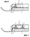
Sur la figure 2, on voit un mode de réalisation du profilé 8 selon l'invention. La figure 2 représente ainsi une coupe du vitrage 1 posé dans la baie de la fenêtre de la carrosserie 7. Ici le cordon de colle 13 au lieu de n'être en contact du côté du vitrage 1, qu'avec le profilé 8, est, en plus, en contact direct avec le vitrage 1 ou plus précisément avec la couche opaque 5. Un primaire d'adhérence 6 peut être prévu pour favoriser l'accrochage du cordon de colle 13 sur le vitrage.In Figure 2, we see an embodiment of the
Une variante de cette configuration est représentée en coupe sur la figure 3. On voit en 9 une deuxième partie du profilé périphérique dont le rôle est de limiter l'expansion de la colle 13. Les autres éléments y compris le cadre opaque 5 restent les mêmes que sur la figure 2.A variant of this configuration is shown in section in Figure 3. We see in 9 a second part of the peripheral profile whose role is to limit
Dans la description et les figures suivantes cette couche 5 en forme de cadre n'est plus représentée pour des raisons de simplicité.In the description and the following figures, this layer 5 in the form of a frame is no longer shown for reasons of simplicity.
La liaison entre le vitrage lui-même et/ou le cadre profilé 8 d'une part qui équipe le vitrage 1 au moment de sa pose et d'autre part la tôle de fixation 2 est réalisée comme on l'a vu grâce au cordon de colle 13. La colle est composée d'un polymère qui est conçu pour adhérer de manière fixe et permanente au cadre 8 et éventuellement au verre ou à la couche 5. Ce sera par exemple un polyuréthane mono-composant polymérisant grâce à l'humidité de l'air. La pression qui doit être exercée pendant la durée de prise du cordon de colle 13 entre le vitrage et la tôle de fixation 2 est également assurée grâce à la lèvre 10 du cadre profilé 8. Elle possède en effet un fort coefficient de frottement et sa raideur relative lui permet de compenser la force de réaction exercée par le cordon de colle 13.The connection between the glazing itself and / or the profiled
La fabrication du cadre profilé 8 se fait d'une manière connue en soi par extrusion d'un polymère adapté et qui adhère sur le vitrage. De tels polymères adaptés à la fabrication d'un cadre profilé sont par exemple des polyuréthanes à un composant sous forme pâteuse qui se transforment sous l'influence de l'humidité de l'air en élastomère à module élevé. Des systèmes polymères de la sorte sont décrits par exemple dans le brevet américain US 3 779 794. Il est également possible d'utiliser des systèmes à deux composants comme ceux qui sont décrits dans les brevets européens EP 0083797 ou EP 0024501. En fonction de la nature de la colle utilisée il aura fallu préparer la surface sur laquelle le cordon est déposé à l'aide de couches de primage telles que la couche 6 selon des procédés connus.The manufacture of the profiled
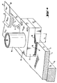
Pour déposer le cadre profilé 8 sur le vitrage 1, on commence comme il est représenté figure 2 par déposer le vitrage sur un cadre support 15 de manière à ce qu'il soit en position horizontale. Il est fixé dans cette position par des moyens adaptés, par exemple des ventouses. On déplace alors la tête d'extrusion le long du bord du vitrage. Cette opération est effectuée de préférence par un robot programmé en conséquence. La tête d'extrusion possède une buse 16 qui est appliquée sur le verre et se déplace dans le ses de la flèche F. La buse 16 possède sur sa face arrière 17 une ouverture calibrée 18. Celle-ci fournit au profilé 8 la forme souhaitée. La stabilité de la forme de la lèvre 10 qui est engendrée par la buse d'extrusion sur une longueur L est telle que la lèvre 10 garde sa forme et sa direction sensiblement horizontale sans avoir besoin d'être soutenue. Ce résultat est obtenu par le choix des propriétés de viscosité et de thixotropie de la matière polymérisable. Celle-ci est amenée à la buse d'extrusion 16 par le tube 19. Ce tube relie la tête d'extrusion 16 à un dispositif de pompage et de dosage qui permet de délivrer le fluide avec la pression et le débit voulus à la tête d'extrusion 16. L'extrusion s'effectue tout le long de la périphérie 3 du vitrage 1. On obtient ainsi un cadre profité 8 fermé sur lui-même. A l'instant précis où la buse 16 atteint l'emplacement où l'extrusion a commencé, le débit de polymère est stoppé de même que le déplacement de la tête d'extrusion. La tête d'extrusion 16 est alors déplacée légèrement dans la direction de la flèche G ce qui l'écarte du verre puis un autre déplacement a lieu perpendiculairement, dans la direction de la flèche H.To deposit the profiled
Comme le montre la figure 5, les opérations précédentes fournissent à l'endroit où la tête d'extrusion 16 s'est écartée du verre, c'est-à-dire à la soudure entre le départ et l'arrivée du cadre profité 8, une discontinuité informe. Ce point de soudure, zone de transition entre deux parties du cadre qui ont un profit parfait, nécessite d'être traité séparément dans une phase de fabrication supplémentaire qui est représentée dans les figures 6 à 8. Pendant l'opération de rectification de la zone de transition du cadre profité 8 le vitrage 1 repose toujours sur son cadre support 15. Dès que la tête d'extrusion a été écartée du vitrage un porte-outil adapté et non représenté sur les figures présente un outil en deux parties sur te vitrage : un pied inférieur 23 qui est associé au porte-outil par la liaison 22 ainsi qu'un poinçon 25 qui est porté, lui, grâce à la liaison 24. Le pied 23 dès qu'il a touché le vitrage par en dessous, se déplace pour venir en butée contre le bord du verre. Le poinçon 25 se présente incliné d'un angle α par rapport au vitrage puis est déplacé dans cette position vers le bas jusqu'à ce que son arête 26 touche la surface du verre. Il entame alors un mouvement de rotation autour de cette arête jusqu' à venir au contact de la feuille de verre et du pied 23. On obtient ainsi que le cadre profité y compris sa lèvre 10 prenne la forme voulue à l'endroit du raccord du profité. L'irrégularité est alors supprimée.As shown in FIG. 5, the preceding operations provide the place where the
La partie supérieure du pied 23 a une forme 29 qui correspond à l'épaisseur du vitrage 1 et qui suit la partie inférieure de la lèvre 10. De même le poinçon 25 a lui aussi une forme précise 30 qui correspond à la limite supérieure du profité 8 et de la lèvre 10. Le mouvement de translation et de basculement subi par le poinçon 25 permet de remplir les lacunes éventuelles du profilé et d'évacuer l'excès de matières dans le prolongement de la lèvre 10 au travers de ta fente 32. Après polymérisation de l'étastomère, l'excès de matière pourra être ébavuré à l'extrémité de la lèvre 10.The upper part of the
Avant de débuter la phase de rectification précédente, c'est-à-dire lorsque l'outil de pressage est en position d'attente, on a déposé sur les surfaces 29 du pied 23 et 30 du poinçon 25 une feuille 33, 34 d'une épaisseur de 4 à 10 µm. La dimension de cette feuille est dans chaque cas celle de la pièce concernée. Les feuilles 33 et 34 doivent épouser exactement les surfaces qu'elles recouvrent. C'est pourquoi aussi bien le pied 23 que le poinçon 24 sont équipés d'une série de perçages 35 qui débouchent sur les surfaces 29 ou 30. Ces perçages sont reliés à des ajutages répartiteurs 36. L'un de ceux-ci est relié par un tuyau souple 37 à une pompe non représentée. La pompe crée une dépression qui plaque les feuilles 33 et 34 sur chacune des deux surfaces 29 et 30. A la fin de l'opération de rectification, les tuyaux 37 sont remplis d'air ce qui permet aux feuilles 33 et 34 de se séparer des outils de pressage. Les feuilles 33 et 34 restent plaquées contre le matériau du profité 8 mais n'y adhèrent pas. On peut donc les en séparer facilement à la fin de la polymérisation.Before starting the previous rectification phase, that is to say when the pressing tool is in the standby position, a
Les feuilles 33, 34 sont constituées d'un matériau dont la surface a des propriétés anti-adhésives par rapport au matériau polymère du profité 8. De bons résultats ont été obtenus avec des feuilles minces de polyester ou de polyéthylène. Dans le cas où le polymère du cadre profité 8 polymérise à l'humidité de l'air, il convient que les feuilles 33 et 34 possèdent une perméabilité suffisante à la vapeur d'eau. Eventuellement, il sera nécessaire de créer une porosité déterminée ou même de percer des microperforations.The
Les feuilles 34, 35 confèrent de plus à la lèvre 10 une rigidité supplémentaire durant la prise. L'excès de matière polymérisable est évacué pendant le processus de rectification ainsi qu'on l'a déjà vu, en direction du prolongement de la lèvre 10 et s'échappe sous forme d'une couche mince entre les deux feuilles 33, 34 où elle va durcir sous forme d'une bavure 41 qui déborde de la bordure 40 de la lèvre 10 (figure 7). Cette bavure 41 sera comme les feuilles 33 et 34, coupée et séparée du profité 8 après polymérisation. Cette opération procure dans la zone de raccordement un aspect soigné à la lèvre 10 du cadre profité 8. Pour terminer on arrache les feuilles 33, 34 restantes pour les séparer du profité 8 et de la lèvre 10.The
Sur la figure 8 on présente un autre mode de réalisation de l'outil de rectification. Le pied 43 a une constitution qui s'apparente à celle du pied 23 de la figure 4. Le pied est relié par une tige de guidage 44, tout comme le poinçon 46, à un porte-outil non représenté. Le pied 43 est ici aussi équipé sur sa surface supérieure de perforations. Celles-ci sont également reliées à un ajutage répartiteur qui est en communication grâce à un tuyau 45 avec une pompe qui peut y créer une dépression.In FIG. 8 another embodiment of the grinding tool is presented. The
Le poinçon 46 est constitué de deux parties : la première 47 qui comporte une surface de référence 48 correspondant à la section du cadre profité qui se trouve au-dessus du verre, et une deuxième partie 49 elle aussi équipée d'une surface catibrée 50 destinée à conformer la lèvre 10. Les deux parties, la première 47 grâce à ta tige de guidage 51, et la deuxième 49 grâce à la tige 52 peuvent être manoeuvrées indépendamment l'une de l'autre. Après que te pied 43 ait été mis en place mais avant que le poinçon n'ait effectué ses propres mouvements, le film plastique qui va ici aussi s'intercaler entre le poinçon et le cadre profité est mis en place à la fois sur le joint informe et sur les surfaces voisines du vitrage 1 et du pied 43. Alors, la partie 47 du poinçon se déplace la première et vient épouser la partie supérieure du profité 8 situé au-dessus du vitrage 1. Enfin, la partie 49 du même poinçon vient à son tour rectifier la forme de la lèvre 10.The
Les exemples de réalisation de l'invention présentés ici sont relatifs au pare-brise d'un véhicule automobile. L'invention est aussi bien valable dans les mêmes conditions pour n'importe quel vitrage comme par exemple les lunettes arrière ou les vitrages de portière, de custode, de hayon, de toit ou de protection de phares. Par ailleurs, la méthode de t'invention convient également à tous les domaines où un vitrage doit être fixé par collage à l'intérieur d'un cadre. Dans le domaine des transports, ce sera le cas par exemple des vitrages de chemin de fer ou de caravane mais les applications dans le domaine du bâtiment, dans celui du mobilier, ou même de l'appareillage ou de l'étectroménager sont également à envisager.The embodiments of the invention presented here relate to the windshield of a motor vehicle. The invention is equally valid under the same conditions for any glazing such as for example the rear glasses or the glazing of the door, rear quarter, tailgate, roof or protection of headlights. Furthermore, the method of the invention is also suitable for all areas where glazing must be fixed by gluing inside a frame. In the transport sector, this will be the case, for example, for railway or caravan glazing, but applications in the building sector, in that of furniture, or even in appliances or household appliances are also to be considered. .
Claims (5)
Priority Applications (1)
| Application Number | Priority Date | Filing Date | Title |
|---|---|---|---|
| EP95117789A EP0703108B1 (en) | 1989-09-12 | 1990-09-06 | Glazing with profile frame, in particular vehicle glazing, and method of applying same |
Applications Claiming Priority (5)
| Application Number | Priority Date | Filing Date | Title |
|---|---|---|---|
| DE3930414 | 1989-09-12 | ||
| DE3930414A DE3930414C2 (en) | 1989-09-12 | 1989-09-12 | Method and device for producing a glass pane provided for direct gluing to the fastening flange of a window opening |
| US531191 | 1990-05-31 | ||
| US07/531,191 US5095669A (en) | 1989-12-13 | 1990-05-31 | Spacer for windshield bracket |
| EP90402445A EP0421833B2 (en) | 1989-09-12 | 1990-09-06 | Glazing with profile frame, in particular vehicle glazing, and process and device for the manufacture of such a glazing |
Related Parent Applications (2)
| Application Number | Title | Priority Date | Filing Date |
|---|---|---|---|
| EP90402445A Division EP0421833B2 (en) | 1989-09-12 | 1990-09-06 | Glazing with profile frame, in particular vehicle glazing, and process and device for the manufacture of such a glazing |
| EP90402445.2 Division | 1990-09-06 |
Related Child Applications (2)
| Application Number | Title | Priority Date | Filing Date |
|---|---|---|---|
| EP95117789A Division EP0703108B1 (en) | 1989-09-12 | 1990-09-06 | Glazing with profile frame, in particular vehicle glazing, and method of applying same |
| EP95117789.8 Division-Into | 1990-09-06 |
Publications (3)
| Publication Number | Publication Date |
|---|---|
| EP0611672A2 true EP0611672A2 (en) | 1994-08-24 |
| EP0611672A3 EP0611672A3 (en) | 1994-11-30 |
| EP0611672B1 EP0611672B1 (en) | 1998-02-25 |
Family
ID=25885068
Family Applications (3)
| Application Number | Title | Priority Date | Filing Date |
|---|---|---|---|
| EP90402445A Expired - Lifetime EP0421833B2 (en) | 1989-09-12 | 1990-09-06 | Glazing with profile frame, in particular vehicle glazing, and process and device for the manufacture of such a glazing |
| EP95117789A Expired - Lifetime EP0703108B1 (en) | 1989-09-12 | 1990-09-06 | Glazing with profile frame, in particular vehicle glazing, and method of applying same |
| EP94105771A Expired - Lifetime EP0611672B1 (en) | 1989-09-12 | 1990-09-06 | Glazing with profile frame, in particular vehicle glazing |
Family Applications Before (2)
| Application Number | Title | Priority Date | Filing Date |
|---|---|---|---|
| EP90402445A Expired - Lifetime EP0421833B2 (en) | 1989-09-12 | 1990-09-06 | Glazing with profile frame, in particular vehicle glazing, and process and device for the manufacture of such a glazing |
| EP95117789A Expired - Lifetime EP0703108B1 (en) | 1989-09-12 | 1990-09-06 | Glazing with profile frame, in particular vehicle glazing, and method of applying same |
Country Status (6)
| Country | Link |
|---|---|
| EP (3) | EP0421833B2 (en) |
| AT (3) | ATE163392T1 (en) |
| DE (3) | DE69033774T2 (en) |
| DK (3) | DK0611672T3 (en) |
| ES (3) | ES2070291T5 (en) |
| FI (1) | FI109343B (en) |
Cited By (3)
| Publication number | Priority date | Publication date | Assignee | Title |
|---|---|---|---|---|
| DE19604397C1 (en) * | 1996-02-07 | 1997-07-31 | Sekurit Saint Gobain Deutsch | Device for extruding a frame-like profile strand onto a glass pane |
| WO2000017002A1 (en) * | 1998-09-24 | 2000-03-30 | Saint-Gobain Vitrage | Glazing with a profiled string rim comprising an overlay appendage |
| WO2001045974A1 (en) * | 1999-12-21 | 2001-06-28 | Saint-Gobain Glass France | Joining of a vehicle pane to a contiguous element |
Families Citing this family (22)
| Publication number | Priority date | Publication date | Assignee | Title |
|---|---|---|---|---|
| US5384995A (en) | 1989-09-12 | 1995-01-31 | St. Gobain Vitrage International | Spacer for windshield bracket |
| US5411696A (en) | 1990-12-27 | 1995-05-02 | Tokai Kogyo Kabushiki Kaisha | Process of making a panel unit |
| DE4123256C1 (en) * | 1991-07-13 | 1992-10-08 | Saint Gobain Vitrage | |
| DE4123588A1 (en) * | 1991-07-17 | 1993-01-21 | Ver Glaswerke Gmbh | METHOD AND DEVICE FOR PRODUCING A VEHICLE WINDOW |
| DE4133662A1 (en) * | 1991-10-11 | 1993-04-15 | Ver Glaswerke Gmbh | GLASS PANEL PRE-EQUIPPED WITH AN ELASTOMER FRAME |
| IT1263204B (en) * | 1992-01-28 | 1996-08-05 | Siv Soc Italiana Vetro | PROCEDURE AND DEVICE FOR JOINING A GASKET ON BOARD ON A GLASS. |
| DE69321649T2 (en) * | 1992-04-28 | 1999-04-15 | Asahi Glass Co. Ltd., Tokio/Tokyo | Process for the production of window glass with a plastic frame |
| DE4232554C1 (en) * | 1992-09-29 | 1994-01-05 | Ver Glaswerke Gmbh | Method for producing a glass pane provided with a molded frame made of a thermoplastic polymer and device for carrying out the method |
| ES2177848T3 (en) * | 1993-01-16 | 2002-12-16 | Saint Gobain | PROCEDURE AND DEVICE FOR THE MANUFACTURE OF A PREEQUIPADO CAR CRYSTAL FOR ADHESION AT AN OPENING. |
| DE4404348A1 (en) * | 1994-02-11 | 1995-08-17 | Fritz Richard Gmbh & Co Kg | Process for the production and installation of a glass pane with a frame, in particular on a vehicle part |
| ATE146412T1 (en) * | 1994-04-20 | 1997-01-15 | Henniges Elastomer Kunststoff | BODY WINDOWS FOR MOTOR VEHICLES |
| DE4421299C2 (en) * | 1994-06-17 | 1996-04-11 | Sekurit Saint Gobain Deutsch | Method and device for reshaping a profile strand extruded onto an object |
| DE4445258C2 (en) * | 1994-12-19 | 1996-10-02 | Sekurit Saint Gobain Deutsch | Method and device for reshaping a profile strand extruded onto an object |
| IT1283895B1 (en) * | 1996-01-25 | 1998-05-07 | Tai Tecnologia Automazione Inn | METHOD AND EQUIPMENT FOR MODELING SEAL SECTIONS MADE BY EXTRUSION OF A VISCOUS FLUID DURING DEPOSIT |
| DE19619356A1 (en) * | 1996-05-14 | 1997-11-20 | Flachglas Ag | Glass unit with an opto-coating |
| DE19721566B4 (en) * | 1996-06-04 | 2014-08-28 | Volkswagen Ag | Method for producing a disk body with a frame made of soft elastic material molded by encapsulation |
| DE19632149C1 (en) * | 1996-08-09 | 1998-02-05 | Sekurit Saint Gobain Deutsch | Form stamp for re-forming a profile strand extruded onto an object |
| FR2757093B1 (en) * | 1996-12-12 | 1999-01-08 | Saint Gobain Vitrage | PROCESS FOR RECTIFICATION OF THE EDGE OF A SHEET ASSEMBLING TWO SUBSTRATES |
| FR2770212B1 (en) * | 1997-10-29 | 1999-11-26 | Eurokera | GLASS MATERIAL PLATE FOR FIXING IN A FRAME |
| PT1324892E (en) † | 2000-10-10 | 2007-10-22 | Saint Gobain | Use of a glazing comprising a profiled string rim for its installation in a recess |
| DE102007009694B4 (en) * | 2007-02-28 | 2016-09-22 | Volkswagen Ag | Mounting arrangement for a vehicle window |
| CN106457778B (en) | 2015-05-15 | 2018-03-30 | 法国圣戈班玻璃厂 | With heat radiation reflectance coating and the glass plate of fixation mounted thereto or potted component |
Citations (6)
| Publication number | Priority date | Publication date | Assignee | Title |
|---|---|---|---|---|
| FR2266669A1 (en) * | 1974-04-03 | 1975-10-31 | Cem Comp Electro Mec | Bonding glass to metal - by injecting liq. adhesive into intermediate cavity formed Using-rings or other seals |
| DE8202672U1 (en) * | 1982-02-03 | 1982-06-24 | Dr.Ing.H.C. F. Porsche Ag, 7000 Stuttgart | Sealing body for a motor vehicle window |
| EP0122636A2 (en) * | 1983-04-19 | 1984-10-24 | Saar-Gummiwerk GmbH | Method of manufacturing a construction element in the form of a disc clasped in an extruded elastomer profile |
| DE3323006A1 (en) * | 1983-06-25 | 1985-01-10 | Daimler-Benz Ag, 7000 Stuttgart | Glazing of windows, in particular front and rear windows, of motor vehicles |
| US4581276A (en) * | 1984-05-25 | 1986-04-08 | Saint-Gobain Vitrage | Adhesive bonding means for mounting glass sheets in a window aperture |
| EP0345134A2 (en) * | 1988-06-03 | 1989-12-06 | Saint-Gobain Vitrage International | Process for producing a motor vehicle glazing ready to be installed |
Family Cites Families (6)
| Publication number | Priority date | Publication date | Assignee | Title |
|---|---|---|---|---|
| BE543200A (en) * | 1955-11-21 | |||
| GB1219511A (en) * | 1968-04-19 | 1971-01-20 | Sachsenring Automobilwerke | Improvements in and relating to a cutting tool for trimming of workpieces of synthetic plastics material |
| FR2543534B1 (en) | 1983-03-31 | 1986-08-14 | Saint Gobain Vitrage | IMPROVEMENT IN MOUNTING BY GLUING A GLASS IN A BAY, ESPECIALLY A MOTOR VEHICLE |
| US4833847A (en) * | 1987-03-12 | 1989-05-30 | Toyoda Gosei Co., Ltd. | Flush mounting molding |
| US4765673A (en) * | 1987-05-04 | 1988-08-23 | General Motors Corporation | Windshield reveal molding |
| FR2619336B1 (en) * | 1987-08-13 | 1989-12-01 | Marechal Ets | PROCESS FOR THE PRODUCTION OF A HOT-GRAINING CYLINDER OF THERMOPLASTIC SHEETS |
-
1990
- 1990-09-06 AT AT94105771T patent/ATE163392T1/en not_active IP Right Cessation
- 1990-09-06 EP EP90402445A patent/EP0421833B2/en not_active Expired - Lifetime
- 1990-09-06 DK DK94105771T patent/DK0611672T3/en active
- 1990-09-06 ES ES90402445T patent/ES2070291T5/en not_active Expired - Lifetime
- 1990-09-06 DK DK95117789T patent/DK0703108T3/en active
- 1990-09-06 EP EP95117789A patent/EP0703108B1/en not_active Expired - Lifetime
- 1990-09-06 DE DE69033774T patent/DE69033774T2/en not_active Expired - Lifetime
- 1990-09-06 AT AT95117789T patent/ATE203719T1/en not_active IP Right Cessation
- 1990-09-06 DK DK90402445.2T patent/DK0421833T3/en active
- 1990-09-06 EP EP94105771A patent/EP0611672B1/en not_active Expired - Lifetime
- 1990-09-06 AT AT90402445T patent/ATE118413T1/en not_active IP Right Cessation
- 1990-09-06 ES ES94105771T patent/ES2113567T3/en not_active Expired - Lifetime
- 1990-09-06 DE DE69032073T patent/DE69032073T2/en not_active Expired - Lifetime
- 1990-09-06 ES ES95117789T patent/ES2160137T3/en not_active Expired - Lifetime
- 1990-09-06 DE DE69016909T patent/DE69016909T3/en not_active Expired - Lifetime
- 1990-09-11 FI FI904485A patent/FI109343B/en active IP Right Grant
Patent Citations (6)
| Publication number | Priority date | Publication date | Assignee | Title |
|---|---|---|---|---|
| FR2266669A1 (en) * | 1974-04-03 | 1975-10-31 | Cem Comp Electro Mec | Bonding glass to metal - by injecting liq. adhesive into intermediate cavity formed Using-rings or other seals |
| DE8202672U1 (en) * | 1982-02-03 | 1982-06-24 | Dr.Ing.H.C. F. Porsche Ag, 7000 Stuttgart | Sealing body for a motor vehicle window |
| EP0122636A2 (en) * | 1983-04-19 | 1984-10-24 | Saar-Gummiwerk GmbH | Method of manufacturing a construction element in the form of a disc clasped in an extruded elastomer profile |
| DE3323006A1 (en) * | 1983-06-25 | 1985-01-10 | Daimler-Benz Ag, 7000 Stuttgart | Glazing of windows, in particular front and rear windows, of motor vehicles |
| US4581276A (en) * | 1984-05-25 | 1986-04-08 | Saint-Gobain Vitrage | Adhesive bonding means for mounting glass sheets in a window aperture |
| EP0345134A2 (en) * | 1988-06-03 | 1989-12-06 | Saint-Gobain Vitrage International | Process for producing a motor vehicle glazing ready to be installed |
Cited By (7)
| Publication number | Priority date | Publication date | Assignee | Title |
|---|---|---|---|---|
| DE19604397C1 (en) * | 1996-02-07 | 1997-07-31 | Sekurit Saint Gobain Deutsch | Device for extruding a frame-like profile strand onto a glass pane |
| WO2000017002A1 (en) * | 1998-09-24 | 2000-03-30 | Saint-Gobain Vitrage | Glazing with a profiled string rim comprising an overlay appendage |
| US6332640B1 (en) | 1998-09-24 | 2001-12-25 | Saint-Gobain Recherche | Window with a profiled bead comprising a covering attachment |
| US6719351B2 (en) | 1998-09-24 | 2004-04-13 | Saint-Gobain Glass France | Window with a profiled bead comprising a covering attachment |
| KR100917942B1 (en) * | 1998-09-24 | 2009-09-21 | 쌩-고벵 글래스 프랑스 | Window |
| WO2001045974A1 (en) * | 1999-12-21 | 2001-06-28 | Saint-Gobain Glass France | Joining of a vehicle pane to a contiguous element |
| US6722731B2 (en) | 1999-12-21 | 2004-04-20 | Saint-Gobain Glass France | Assembly of a vehicle window glass with a contiguous element |
Also Published As
| Publication number | Publication date |
|---|---|
| ES2113567T3 (en) | 1998-05-01 |
| EP0421833A3 (en) | 1991-07-31 |
| ATE163392T1 (en) | 1998-03-15 |
| DE69032073T2 (en) | 1998-08-20 |
| ATE118413T1 (en) | 1995-03-15 |
| DE69016909D1 (en) | 1995-03-23 |
| ES2160137T3 (en) | 2001-11-01 |
| EP0611672A3 (en) | 1994-11-30 |
| FI904485A0 (en) | 1990-09-11 |
| DK0703108T3 (en) | 2001-11-26 |
| EP0421833B2 (en) | 1999-08-11 |
| DE69016909T2 (en) | 1995-10-05 |
| EP0703108A1 (en) | 1996-03-27 |
| ATE203719T1 (en) | 2001-08-15 |
| DE69016909T3 (en) | 2000-09-14 |
| EP0611672B1 (en) | 1998-02-25 |
| ES2070291T5 (en) | 1999-12-16 |
| EP0421833A2 (en) | 1991-04-10 |
| EP0421833B1 (en) | 1995-02-15 |
| DE69033774T2 (en) | 2002-06-20 |
| ES2070291T3 (en) | 1995-06-01 |
| FI109343B (en) | 2002-07-15 |
| DE69033774D1 (en) | 2001-09-06 |
| DE69032073D1 (en) | 1998-04-02 |
| DK0611672T3 (en) | 1998-09-23 |
| EP0703108B1 (en) | 2001-08-01 |
| DK0421833T3 (en) | 1995-06-26 |
Similar Documents
| Publication | Publication Date | Title |
|---|---|---|
| EP0611672B1 (en) | Glazing with profile frame, in particular vehicle glazing | |
| EP0620134B1 (en) | Vehicle glazing preassembled in order to be glued in an opening and method for its manufacture | |
| EP1324892B2 (en) | Use of a glazing comprising a profiled string rim for its installation in a recess | |
| EP0524060B1 (en) | Method and device for making glazing with a polymer-based frame | |
| EP0885135B1 (en) | Glazing moulded from a casting and method for making same | |
| EP0248707A2 (en) | Window glass provided with an insertable marginal trimming strip | |
| EP0119906A1 (en) | Sealing joint for mounting a security glass pane, especially a motor car windshield in an aperture of the vehicle body | |
| LU84319A1 (en) | PROCESS FOR FINISHING REINFORCED RESIN PRODUCTS, PARTICULARLY HELMETS, AND PRODUCTS MANUFACTURED THEREBY | |
| FR2683190A1 (en) | Section for a windscreen and method for manufacturing it | |
| EP1441890B1 (en) | Method and device for producing a profiled rim on a component. | |
| EP0531201B1 (en) | Assembling of motor vehicle glazing from inside | |
| EP0537067B1 (en) | Vehicle glazing pre-assembled with an elastomeric frame | |
| WO2001098613A2 (en) | Mobile glazing pre-adjusted in position | |
| EP0782501A1 (en) | Method for fabricating a material panel lined with an aspect zone, particularly textile | |
| EP2525960A1 (en) | Method for manufacturing an inner covering assembly on a member of a forming tool | |
| EP2812169B1 (en) | Method for producing a vanity unit assembly and vanity unit assembly obtained by this method | |
| EP1355797B1 (en) | Method and device for producing a profiled edge section for a glass pane | |
| EP0467785B1 (en) | Method for manufacturing and fastening a seat upholstery on a seat frame | |
| FR2848976A1 (en) | Plastic body component for motor vehicle has reinforcing member attached to inner surface by pressure-sensitive adhesive | |
| FR2857911A1 (en) | Trim extrusion for fixed glass panel e.g. in motor vehicle has flexible seal that folds over edge of glass when applied against adhesive bead | |
| WO2015015078A1 (en) | Inner decorative trim panel for a support | |
| FR2757804A1 (en) | GLAZING EQUIPPED WITH A PLASTIC FRAME, WORKPIECES AND METHOD FOR MANUFACTURING THE SAME | |
| EP0594513B1 (en) | Process for making a ski | |
| EP1095840B1 (en) | Steering wheel for motor vehicle and method for its manufacture | |
| FR2598152A1 (en) | Process and device for coating a thin article with a coating in sheet form and product obtained |
Legal Events
| Date | Code | Title | Description |
|---|---|---|---|
| PUAI | Public reference made under article 153(3) epc to a published international application that has entered the european phase |
Free format text: ORIGINAL CODE: 0009012 |
|
| AC | Divisional application: reference to earlier application |
Ref document number: 421833 Country of ref document: EP |
|
| AK | Designated contracting states |
Kind code of ref document: A2 Designated state(s): AT BE CH DE DK ES FR GB IT LI LU NL SE |
|
| PUAL | Search report despatched |
Free format text: ORIGINAL CODE: 0009013 |
|
| AK | Designated contracting states |
Kind code of ref document: A3 Designated state(s): AT BE CH DE DK ES FR GB IT LI LU NL SE |
|
| 17P | Request for examination filed |
Effective date: 19950306 |
|
| RAP1 | Party data changed (applicant data changed or rights of an application transferred) |
Owner name: VEGLA VEREINIGTE GLASWERKE GMBH Owner name: SAINT-GOBAIN VITRAGE |
|
| 17Q | First examination report despatched |
Effective date: 19960917 |
|
| GRAG | Despatch of communication of intention to grant |
Free format text: ORIGINAL CODE: EPIDOS AGRA |
|
| GRAG | Despatch of communication of intention to grant |
Free format text: ORIGINAL CODE: EPIDOS AGRA |
|
| GRAH | Despatch of communication of intention to grant a patent |
Free format text: ORIGINAL CODE: EPIDOS IGRA |
|
| GRAH | Despatch of communication of intention to grant a patent |
Free format text: ORIGINAL CODE: EPIDOS IGRA |
|
| GRAA | (expected) grant |
Free format text: ORIGINAL CODE: 0009210 |
|
| DX | Miscellaneous (deleted) | ||
| AC | Divisional application: reference to earlier application |
Ref document number: 421833 Country of ref document: EP |
|
| AK | Designated contracting states |
Kind code of ref document: B1 Designated state(s): AT BE CH DE DK ES FR GB IT LI LU NL SE |
|
| REF | Corresponds to: |
Ref document number: 163392 Country of ref document: AT Date of ref document: 19980315 Kind code of ref document: T |
|
| REG | Reference to a national code |
Ref country code: CH Ref legal event code: EP |
|
| REF | Corresponds to: |
Ref document number: 69032073 Country of ref document: DE Date of ref document: 19980402 |
|
| ITF | It: translation for a ep patent filed | ||
| REG | Reference to a national code |
Ref country code: CH Ref legal event code: NV Representative=s name: KIRKER & CIE SA |
|
| REG | Reference to a national code |
Ref country code: ES Ref legal event code: FG2A Ref document number: 2113567 Country of ref document: ES Kind code of ref document: T3 |
|
| GBT | Gb: translation of ep patent filed (gb section 77(6)(a)/1977) |
Effective date: 19980414 |
|
| REG | Reference to a national code |
Ref country code: DK Ref legal event code: T3 |
|
| PLBQ | Unpublished change to opponent data |
Free format text: ORIGINAL CODE: EPIDOS OPPO |
|
| PLBI | Opposition filed |
Free format text: ORIGINAL CODE: 0009260 |
|
| PLBF | Reply of patent proprietor to notice(s) of opposition |
Free format text: ORIGINAL CODE: EPIDOS OBSO |
|
| 26 | Opposition filed |
Opponent name: SCHADE GMBH & CO.KG Effective date: 19981125 |
|
| NLR1 | Nl: opposition has been filed with the epo |
Opponent name: SCHADE GMBH & CO.KG |
|
| PLBF | Reply of patent proprietor to notice(s) of opposition |
Free format text: ORIGINAL CODE: EPIDOS OBSO |
|
| PLBF | Reply of patent proprietor to notice(s) of opposition |
Free format text: ORIGINAL CODE: EPIDOS OBSO |
|
| PLBO | Opposition rejected |
Free format text: ORIGINAL CODE: EPIDOS REJO |
|
| PLBN | Opposition rejected |
Free format text: ORIGINAL CODE: 0009273 |
|
| STAA | Information on the status of an ep patent application or granted ep patent |
Free format text: STATUS: OPPOSITION REJECTED |
|
| 27O | Opposition rejected |
Effective date: 20000128 |
|
| NLR2 | Nl: decision of opposition | ||
| REG | Reference to a national code |
Ref country code: GB Ref legal event code: IF02 |
|
| PGFP | Annual fee paid to national office [announced via postgrant information from national office to epo] |
Ref country code: LU Payment date: 20080912 Year of fee payment: 19 Ref country code: DK Payment date: 20080912 Year of fee payment: 19 |
|
| PGFP | Annual fee paid to national office [announced via postgrant information from national office to epo] |
Ref country code: NL Payment date: 20080903 Year of fee payment: 19 Ref country code: IT Payment date: 20080926 Year of fee payment: 19 Ref country code: FR Payment date: 20080909 Year of fee payment: 19 Ref country code: AT Payment date: 20080912 Year of fee payment: 19 |
|
| PGFP | Annual fee paid to national office [announced via postgrant information from national office to epo] |
Ref country code: GB Payment date: 20080910 Year of fee payment: 19 |
|
| PGFP | Annual fee paid to national office [announced via postgrant information from national office to epo] |
Ref country code: CH Payment date: 20081002 Year of fee payment: 19 |
|
| PGFP | Annual fee paid to national office [announced via postgrant information from national office to epo] |
Ref country code: SE Payment date: 20080908 Year of fee payment: 19 Ref country code: ES Payment date: 20081021 Year of fee payment: 19 Ref country code: BE Payment date: 20080918 Year of fee payment: 19 |
|
| PGFP | Annual fee paid to national office [announced via postgrant information from national office to epo] |
Ref country code: DE Payment date: 20090903 Year of fee payment: 20 |
|
| BERE | Be: lapsed |
Owner name: *VEGLA VEREINIGTE GLASWERKE G.M.B.H. Effective date: 20090930 Owner name: *SAINT-GOBAIN VITRAGE Effective date: 20090930 |
|
| REG | Reference to a national code |
Ref country code: NL Ref legal event code: V1 Effective date: 20100401 |
|
| REG | Reference to a national code |
Ref country code: CH Ref legal event code: PL |
|
| EUG | Se: european patent has lapsed | ||
| REG | Reference to a national code |
Ref country code: DK Ref legal event code: EBP |
|
| GBPC | Gb: european patent ceased through non-payment of renewal fee |
Effective date: 20090906 |
|
| REG | Reference to a national code |
Ref country code: FR Ref legal event code: ST Effective date: 20100531 |
|
| PG25 | Lapsed in a contracting state [announced via postgrant information from national office to epo] |
Ref country code: AT Free format text: LAPSE BECAUSE OF NON-PAYMENT OF DUE FEES Effective date: 20090906 |
|
| PG25 | Lapsed in a contracting state [announced via postgrant information from national office to epo] |
Ref country code: NL Free format text: LAPSE BECAUSE OF NON-PAYMENT OF DUE FEES Effective date: 20100401 Ref country code: FR Free format text: LAPSE BECAUSE OF NON-PAYMENT OF DUE FEES Effective date: 20090930 |
|
| PG25 | Lapsed in a contracting state [announced via postgrant information from national office to epo] |
Ref country code: BE Free format text: LAPSE BECAUSE OF NON-PAYMENT OF DUE FEES Effective date: 20090930 |
|
| PG25 | Lapsed in a contracting state [announced via postgrant information from national office to epo] |
Ref country code: LI Free format text: LAPSE BECAUSE OF NON-PAYMENT OF DUE FEES Effective date: 20090930 Ref country code: CH Free format text: LAPSE BECAUSE OF NON-PAYMENT OF DUE FEES Effective date: 20090930 |
|
| PG25 | Lapsed in a contracting state [announced via postgrant information from national office to epo] |
Ref country code: GB Free format text: LAPSE BECAUSE OF NON-PAYMENT OF DUE FEES Effective date: 20090906 |
|
| PG25 | Lapsed in a contracting state [announced via postgrant information from national office to epo] |
Ref country code: DK Free format text: LAPSE BECAUSE OF NON-PAYMENT OF DUE FEES Effective date: 20090930 |
|
| REG | Reference to a national code |
Ref country code: ES Ref legal event code: FD2A Effective date: 20110223 |
|
| PG25 | Lapsed in a contracting state [announced via postgrant information from national office to epo] |
Ref country code: IT Free format text: LAPSE BECAUSE OF NON-PAYMENT OF DUE FEES Effective date: 20090906 |
|
| PG25 | Lapsed in a contracting state [announced via postgrant information from national office to epo] |
Ref country code: LU Free format text: LAPSE BECAUSE OF NON-PAYMENT OF DUE FEES Effective date: 20090906 |
|
| PG25 | Lapsed in a contracting state [announced via postgrant information from national office to epo] |
Ref country code: SE Free format text: LAPSE BECAUSE OF NON-PAYMENT OF DUE FEES Effective date: 20090907 |
|
| PG25 | Lapsed in a contracting state [announced via postgrant information from national office to epo] |
Ref country code: ES Free format text: LAPSE BECAUSE OF NON-PAYMENT OF DUE FEES Effective date: 20090907 |
|
| PG25 | Lapsed in a contracting state [announced via postgrant information from national office to epo] |
Ref country code: DE Free format text: LAPSE BECAUSE OF EXPIRATION OF PROTECTION Effective date: 20100906 |