EP0620134B1 - Vehicle glazing preassembled in order to be glued in an opening and method for its manufacture - Google Patents
Vehicle glazing preassembled in order to be glued in an opening and method for its manufacture Download PDFInfo
- Publication number
- EP0620134B1 EP0620134B1 EP94400086A EP94400086A EP0620134B1 EP 0620134 B1 EP0620134 B1 EP 0620134B1 EP 94400086 A EP94400086 A EP 94400086A EP 94400086 A EP94400086 A EP 94400086A EP 0620134 B1 EP0620134 B1 EP 0620134B1
- Authority
- EP
- European Patent Office
- Prior art keywords
- profile
- adhesive
- frame
- glazing
- pane
- Prior art date
- Legal status (The legal status is an assumption and is not a legal conclusion. Google has not performed a legal analysis and makes no representation as to the accuracy of the status listed.)
- Expired - Lifetime
Links
Images


Classifications
-
- B—PERFORMING OPERATIONS; TRANSPORTING
- B60—VEHICLES IN GENERAL
- B60J—WINDOWS, WINDSCREENS, NON-FIXED ROOFS, DOORS, OR SIMILAR DEVICES FOR VEHICLES; REMOVABLE EXTERNAL PROTECTIVE COVERINGS SPECIALLY ADAPTED FOR VEHICLES
- B60J1/00—Windows; Windscreens; Accessories therefor
- B60J1/02—Windows; Windscreens; Accessories therefor arranged at the vehicle front, e.g. structure of the glazing, mounting of the glazing
-
- B—PERFORMING OPERATIONS; TRANSPORTING
- B60—VEHICLES IN GENERAL
- B60J—WINDOWS, WINDSCREENS, NON-FIXED ROOFS, DOORS, OR SIMILAR DEVICES FOR VEHICLES; REMOVABLE EXTERNAL PROTECTIVE COVERINGS SPECIALLY ADAPTED FOR VEHICLES
- B60J1/00—Windows; Windscreens; Accessories therefor
- B60J1/08—Windows; Windscreens; Accessories therefor arranged at vehicle sides
- B60J1/10—Windows; Windscreens; Accessories therefor arranged at vehicle sides fixedly mounted
-
- B—PERFORMING OPERATIONS; TRANSPORTING
- B29—WORKING OF PLASTICS; WORKING OF SUBSTANCES IN A PLASTIC STATE IN GENERAL
- B29C—SHAPING OR JOINING OF PLASTICS; SHAPING OF MATERIAL IN A PLASTIC STATE, NOT OTHERWISE PROVIDED FOR; AFTER-TREATMENT OF THE SHAPED PRODUCTS, e.g. REPAIRING
- B29C45/00—Injection moulding, i.e. forcing the required volume of moulding material through a nozzle into a closed mould; Apparatus therefor
- B29C45/14—Injection moulding, i.e. forcing the required volume of moulding material through a nozzle into a closed mould; Apparatus therefor incorporating preformed parts or layers, e.g. injection moulding around inserts or for coating articles
- B29C45/14336—Coating a portion of the article, e.g. the edge of the article
- B29C45/14434—Coating brittle material, e.g. glass
-
- B—PERFORMING OPERATIONS; TRANSPORTING
- B29—WORKING OF PLASTICS; WORKING OF SUBSTANCES IN A PLASTIC STATE IN GENERAL
- B29C—SHAPING OR JOINING OF PLASTICS; SHAPING OF MATERIAL IN A PLASTIC STATE, NOT OTHERWISE PROVIDED FOR; AFTER-TREATMENT OF THE SHAPED PRODUCTS, e.g. REPAIRING
- B29C45/00—Injection moulding, i.e. forcing the required volume of moulding material through a nozzle into a closed mould; Apparatus therefor
- B29C45/17—Component parts, details or accessories; Auxiliary operations
- B29C45/40—Removing or ejecting moulded articles
- B29C45/44—Removing or ejecting moulded articles for undercut articles
- B29C45/4407—Removing or ejecting moulded articles for undercut articles by flexible movement of undercut portions of the articles
-
- B—PERFORMING OPERATIONS; TRANSPORTING
- B29—WORKING OF PLASTICS; WORKING OF SUBSTANCES IN A PLASTIC STATE IN GENERAL
- B29C—SHAPING OR JOINING OF PLASTICS; SHAPING OF MATERIAL IN A PLASTIC STATE, NOT OTHERWISE PROVIDED FOR; AFTER-TREATMENT OF THE SHAPED PRODUCTS, e.g. REPAIRING
- B29C65/00—Joining or sealing of preformed parts, e.g. welding of plastics materials; Apparatus therefor
- B29C65/76—Making non-permanent or releasable joints
-
- B—PERFORMING OPERATIONS; TRANSPORTING
- B29—WORKING OF PLASTICS; WORKING OF SUBSTANCES IN A PLASTIC STATE IN GENERAL
- B29C—SHAPING OR JOINING OF PLASTICS; SHAPING OF MATERIAL IN A PLASTIC STATE, NOT OTHERWISE PROVIDED FOR; AFTER-TREATMENT OF THE SHAPED PRODUCTS, e.g. REPAIRING
- B29C66/00—General aspects of processes or apparatus for joining preformed parts
- B29C66/01—General aspects dealing with the joint area or with the area to be joined
- B29C66/05—Particular design of joint configurations
- B29C66/10—Particular design of joint configurations particular design of the joint cross-sections
- B29C66/11—Joint cross-sections comprising a single joint-segment, i.e. one of the parts to be joined comprising a single joint-segment in the joint cross-section
- B29C66/112—Single lapped joints
- B29C66/1122—Single lap to lap joints, i.e. overlap joints
-
- B—PERFORMING OPERATIONS; TRANSPORTING
- B29—WORKING OF PLASTICS; WORKING OF SUBSTANCES IN A PLASTIC STATE IN GENERAL
- B29C—SHAPING OR JOINING OF PLASTICS; SHAPING OF MATERIAL IN A PLASTIC STATE, NOT OTHERWISE PROVIDED FOR; AFTER-TREATMENT OF THE SHAPED PRODUCTS, e.g. REPAIRING
- B29C66/00—General aspects of processes or apparatus for joining preformed parts
- B29C66/01—General aspects dealing with the joint area or with the area to be joined
- B29C66/05—Particular design of joint configurations
- B29C66/10—Particular design of joint configurations particular design of the joint cross-sections
- B29C66/12—Joint cross-sections combining only two joint-segments; Tongue and groove joints; Tenon and mortise joints; Stepped joint cross-sections
- B29C66/124—Tongue and groove joints
- B29C66/1244—Tongue and groove joints characterised by the male part, i.e. the part comprising the tongue
- B29C66/12441—Tongue and groove joints characterised by the male part, i.e. the part comprising the tongue being a single wall
-
- B—PERFORMING OPERATIONS; TRANSPORTING
- B29—WORKING OF PLASTICS; WORKING OF SUBSTANCES IN A PLASTIC STATE IN GENERAL
- B29C—SHAPING OR JOINING OF PLASTICS; SHAPING OF MATERIAL IN A PLASTIC STATE, NOT OTHERWISE PROVIDED FOR; AFTER-TREATMENT OF THE SHAPED PRODUCTS, e.g. REPAIRING
- B29C66/00—General aspects of processes or apparatus for joining preformed parts
- B29C66/50—General aspects of joining tubular articles; General aspects of joining long products, i.e. bars or profiled elements; General aspects of joining single elements to tubular articles, hollow articles or bars; General aspects of joining several hollow-preforms to form hollow or tubular articles
- B29C66/51—Joining tubular articles, profiled elements or bars; Joining single elements to tubular articles, hollow articles or bars; Joining several hollow-preforms to form hollow or tubular articles
- B29C66/53—Joining single elements to tubular articles, hollow articles or bars
- B29C66/534—Joining single elements to open ends of tubular or hollow articles or to the ends of bars
- B29C66/5346—Joining single elements to open ends of tubular or hollow articles or to the ends of bars said single elements being substantially flat
-
- B—PERFORMING OPERATIONS; TRANSPORTING
- B29—WORKING OF PLASTICS; WORKING OF SUBSTANCES IN A PLASTIC STATE IN GENERAL
- B29C—SHAPING OR JOINING OF PLASTICS; SHAPING OF MATERIAL IN A PLASTIC STATE, NOT OTHERWISE PROVIDED FOR; AFTER-TREATMENT OF THE SHAPED PRODUCTS, e.g. REPAIRING
- B29C66/00—General aspects of processes or apparatus for joining preformed parts
- B29C66/70—General aspects of processes or apparatus for joining preformed parts characterised by the composition, physical properties or the structure of the material of the parts to be joined; Joining with non-plastics material
- B29C66/71—General aspects of processes or apparatus for joining preformed parts characterised by the composition, physical properties or the structure of the material of the parts to be joined; Joining with non-plastics material characterised by the composition of the plastics material of the parts to be joined
-
- B—PERFORMING OPERATIONS; TRANSPORTING
- B60—VEHICLES IN GENERAL
- B60J—WINDOWS, WINDSCREENS, NON-FIXED ROOFS, DOORS, OR SIMILAR DEVICES FOR VEHICLES; REMOVABLE EXTERNAL PROTECTIVE COVERINGS SPECIALLY ADAPTED FOR VEHICLES
- B60J10/00—Sealing arrangements
- B60J10/30—Sealing arrangements characterised by the fastening means
- B60J10/34—Sealing arrangements characterised by the fastening means using adhesives
-
- B—PERFORMING OPERATIONS; TRANSPORTING
- B60—VEHICLES IN GENERAL
- B60J—WINDOWS, WINDSCREENS, NON-FIXED ROOFS, DOORS, OR SIMILAR DEVICES FOR VEHICLES; REMOVABLE EXTERNAL PROTECTIVE COVERINGS SPECIALLY ADAPTED FOR VEHICLES
- B60J10/00—Sealing arrangements
- B60J10/70—Sealing arrangements specially adapted for windows or windscreens
-
- C—CHEMISTRY; METALLURGY
- C03—GLASS; MINERAL OR SLAG WOOL
- C03C—CHEMICAL COMPOSITION OF GLASSES, GLAZES OR VITREOUS ENAMELS; SURFACE TREATMENT OF GLASS; SURFACE TREATMENT OF FIBRES OR FILAMENTS MADE FROM GLASS, MINERALS OR SLAGS; JOINING GLASS TO GLASS OR OTHER MATERIALS
- C03C17/00—Surface treatment of glass, not in the form of fibres or filaments, by coating
- C03C17/28—Surface treatment of glass, not in the form of fibres or filaments, by coating with organic material
- C03C17/32—Surface treatment of glass, not in the form of fibres or filaments, by coating with organic material with synthetic or natural resins
- C03C17/328—Polyolefins
-
- C—CHEMISTRY; METALLURGY
- C03—GLASS; MINERAL OR SLAG WOOL
- C03C—CHEMICAL COMPOSITION OF GLASSES, GLAZES OR VITREOUS ENAMELS; SURFACE TREATMENT OF GLASS; SURFACE TREATMENT OF FIBRES OR FILAMENTS MADE FROM GLASS, MINERALS OR SLAGS; JOINING GLASS TO GLASS OR OTHER MATERIALS
- C03C27/00—Joining pieces of glass to pieces of other inorganic material; Joining glass to glass other than by fusing
- C03C27/04—Joining glass to metal by means of an interlayer
- C03C27/048—Joining glass to metal by means of an interlayer consisting of an adhesive specially adapted for that purpose
-
- B—PERFORMING OPERATIONS; TRANSPORTING
- B29—WORKING OF PLASTICS; WORKING OF SUBSTANCES IN A PLASTIC STATE IN GENERAL
- B29C—SHAPING OR JOINING OF PLASTICS; SHAPING OF MATERIAL IN A PLASTIC STATE, NOT OTHERWISE PROVIDED FOR; AFTER-TREATMENT OF THE SHAPED PRODUCTS, e.g. REPAIRING
- B29C66/00—General aspects of processes or apparatus for joining preformed parts
- B29C66/01—General aspects dealing with the joint area or with the area to be joined
- B29C66/05—Particular design of joint configurations
- B29C66/303—Particular design of joint configurations the joint involving an anchoring effect
- B29C66/3032—Particular design of joint configurations the joint involving an anchoring effect making use of protusions or cavities belonging to at least one of the parts to be joined
- B29C66/30325—Particular design of joint configurations the joint involving an anchoring effect making use of protusions or cavities belonging to at least one of the parts to be joined making use of cavities belonging to at least one of the parts to be joined
-
- Y—GENERAL TAGGING OF NEW TECHNOLOGICAL DEVELOPMENTS; GENERAL TAGGING OF CROSS-SECTIONAL TECHNOLOGIES SPANNING OVER SEVERAL SECTIONS OF THE IPC; TECHNICAL SUBJECTS COVERED BY FORMER USPC CROSS-REFERENCE ART COLLECTIONS [XRACs] AND DIGESTS
- Y10—TECHNICAL SUBJECTS COVERED BY FORMER USPC
- Y10T—TECHNICAL SUBJECTS COVERED BY FORMER US CLASSIFICATION
- Y10T428/00—Stock material or miscellaneous articles
- Y10T428/24—Structurally defined web or sheet [e.g., overall dimension, etc.]
- Y10T428/2419—Fold at edge
- Y10T428/24198—Channel-shaped edge component [e.g., binding, etc.]
-
- Y—GENERAL TAGGING OF NEW TECHNOLOGICAL DEVELOPMENTS; GENERAL TAGGING OF CROSS-SECTIONAL TECHNOLOGIES SPANNING OVER SEVERAL SECTIONS OF THE IPC; TECHNICAL SUBJECTS COVERED BY FORMER USPC CROSS-REFERENCE ART COLLECTIONS [XRACs] AND DIGESTS
- Y10—TECHNICAL SUBJECTS COVERED BY FORMER USPC
- Y10T—TECHNICAL SUBJECTS COVERED BY FORMER US CLASSIFICATION
- Y10T428/00—Stock material or miscellaneous articles
- Y10T428/29—Coated or structually defined flake, particle, cell, strand, strand portion, rod, filament, macroscopic fiber or mass thereof
- Y10T428/2902—Channel shape
Definitions
- the invention relates to a glazing for mounting by gluing on the sheet of a bay, in particular an automotive glazing comprising a frame-shaped profile at its periphery, a profile which has a U-shaped section directed towards the sheet of the bay and is made of a polymer, the profile comprising on either side of the U two wings fitted inwards with ribs used for hanging the bead of adhesive placed inside said U and the method for manufacturing it.
- Glazing of the above type is known from document EP-B-0 258 128.
- the connection between the pre-fitted glazing and the sheet metal of the window opening is essentially made by an adhesive bond between the glue and the profile. polymerized in the form of a frame.
- the structure of the hollow part of the profile with its longitudinal ribs has the function in this case of further improving the connection between the laying adhesive and the polymer of the profile.
- the frame-shaped polymerized profile is formed in the known glazing of polyurethane either with a single-component system which cures with moisture or with a two-component system which react immediately after their mixing upon extrusion on the glazing.
- the invention also gives itself the task of allowing rapid hardening of the laying adhesive so as to allow, if necessary, disassembly of the glazing which has just been installed, shortly after its installation in the bay.
- the invention proposes, to achieve this object a glazing of the type disclosed in EP-A-0 258 128 as defined in the preamble of claim 1; this glazing being characterized by having on the one hand a frame-shaped profile based on a thermoplastic polyolefin elastomer made of an isotactic polypropylene and an ethylene-propylene-diene rubber and on the other a glue based on a one-component polyurethane system which cures with humidity.
- pre-equipped glazing can be fitted without any additional preparation thanks to traditional bonding methods. It is sufficient that after having deposited a bead of installation adhesive inside the U-shaped profile, the assembly is placed in the bay. After the glue has hardened, the glazing can be removed from its rebate at any time by simply pressing it. During this operation, the sides of the U-profile are deformed and move away from the hardened adhesive.
- This glazing installation technique is particularly advantageous in the case of automotive glazing because it allows to simply dismantle a glazing which has just been installed while allowing its subsequent reuse. So when you have to make a paint connection on a body, in the vicinity of a windshield for example, you can perform all touch-up operations after dismantling the glazing. It is enough at the end of the operation to proceed with the installation as the first time. Likewise at the end of the life of an automobile, it is very easy to separate the glazing from the painted sheet metal so as to recycle them.
- thermoplastic polyolefin elastomer based on isotactic polypropylene and ethylene-propylene-diene rubber (EPDM)
- EPDM ethylene-propylene-diene rubber
- the product SANTOPRENE A type 111-64 from the company Advanced-Elastomer-Systems
- the BETASEAL product from Gurit-Essex was particularly interesting. The combination of these two materials provides particularly satisfactory mechanical properties to the assembly as well as conditions of adhesion between them adapted to the problem.
- FIG. 1 we see a car window pre-equipped for direct mounting by gluing in the bay of an automobile.
- the glazing 1 is provided with a polymerized frame 2 deposited on one side of the glass by extrusion.
- the device for producing such glazing is shown in FIG. 2.
- the glazing shown in FIG. 1 is equipped on the side intended to be placed opposite the sheet metal of the bodywork with a deposit 3 in the form of a frame made of hot-baked enamel. After depositing on the frame 3 of a suitable primer, the profile 2 is deposited by extrusion on the enamel 3.
- the profile 2 has a section which essentially has a U shape with a bottom 5 and two wings 6 and 7.
- the profile 2 is also equipped with a lip 8 which performs sealing and centering functions.
- Profile 2 is made of a thermoplastic material consisting essentially of a polyolefin elastomer based on isotactic polypropylene and ethylene-propylene-diene rubber (EPDM).
- EPDM ethylene-propylene-diene rubber
- a product which is perfectly suited is the SANTOPRENE from the Advanced-Elastomer-System Company.
- the primer deposited on the enamel layer 3 advantageously consists of a two-component polyurethane system modified in a solvent. This can be a mixture of trichlorethylene and 1,1,1 - trichloroethane and methylene chloride. These are for example the products X-8310 from the Henkel Company or AK-920 from Koemmerling.
- the lateral wings 6 and 7 of the profile have longitudinal ribs.
- the internal space of the limited profile by the side wings widens downwards, it thus takes the form of a Christmas tree.
- this internal space is filled with the installation adhesive 10.
- This adhesive intended to adhere to the sheet 38 which limits the opening of the bodywork has the characteristic of not establishing any adhesive link with the profile 2. The consequence is that there is no bonding between the adhesive and the profile and that the assembly will only hold after hardening of the glue thanks to a mechanical coupling between the hardened glue 10 and the profile 2.
- the glue 10 is deposited in the hollow of the profile 2 using a nozzle in such a way that it completely fills the hollow of the profile and that it also overflows in the form of a protrusion 11. This constitutes the reserve of glue which will allow the fixing by gluing of all of the automotive glazing in the bay.
- FIG. 2 we find the glazing 1 placed precisely on a support 13 to allow the deposition of the polymer frame 2.
- the glazing 1 is heated to a temperature of 70 to 90 ° C.
- the robot 15 has an arm and a "hand" 14.
- the latter is equipped with an extrusion nozzle 16.
- the nozzle has a calibrated orifice 17 which makes it possible to extrude the profile 2 with the desired section.
- the extrusion nozzle 16 is moved by the robot 15 to the edge of the glazing 1 according to a program provided in advance.
- the commands are supplied by a processor 19 via the connections 20.
- the extrusion nozzle 16 is equipped with a heating element 21 so as to maintain the material to be extruded at a temperature of approximately 200 ° C., temperature necessary to allow extrusion in good conditions.
- the material to be extruded is in the form of granules, they are introduced into the hopper 23 from where they are introduced into the screw extruder 24 where they are melted and taken under pressure to the extrusion head 16.
- the cylinder 25 of the extruder 24 which contains an endless screw is heated by several heating rings 26. This system makes it possible to maintain at a uniform temperature all elements of the extruder.
- the motor 27 which drives the screw 24 is controlled, like the robot 15, by the processor 19.
- the connection between the cylinder 25 of the extruder 24 and the extrusion nozzle 16 is made by means of a heating pipe 30 capable of withstanding high pressures.
- the heating pipe 30 must indeed withstand pressures up to 250 bars. It includes heating resistors 31 which guarantee that the pipe 30 is at a temperature of the order of 200 ° C.
- this pipe 30 must be flexible enough to be able to allow the displacement of the nozzle 16 without limitation during the extrusion that the robot 15 performs at the periphery of the glazing 1.
- the high pressure hose 30 naturally has a certain resistance to torsion which could possibly be troublesome during extrusion.
- this "hand” has itself rotated 360 ° relative to the other end of the pipe 30.
- it is fitted with one or more rotary joints 32.
- the glazing 34 pre-equipped according to the invention has a polymer frame 35 obtained by an encapsulation technique that is to say by high pressure molding.
- the glazing 34 is embedded in its elastomer frame 35.
- This frame 35 is equipped with an overhanging lip 36.
- the lip 36 rests on the rebate 37 of the frame of the window and thus closes the space left free between the glazing and the bodywork.
- This lip which generally occupies the entire periphery of the glazing, also allows it to center automatically in the opening during installation.
- the sheet 38 of the opening which is opposite the edge of the glazing and substantially parallel to it is used for bonding the pre-fitted glazing in the opening.
- the profiled frame 35 has, opposite the sheet 38, a U-shaped section 39, the lateral wings 40, 41 of which are provided with longitudinal ribs on their internal faces.
- the width of the U decreases from its base towards its ends.
- the hollow is filled with the installation adhesive 42.
- the materials used respectively to constitute the encapsulated frame 35 and the installation adhesive 42 are the same as those which have been described during the description of FIG. 1.
- FIG. 3 it can be seen how the protuberance of the laying adhesive which has been deposited inside the hollow of the U-shaped profile is crushed so as to adhere to the sheet 38 of the bay. It is in this form that it will harden to then ensure mechanical attachment between the profiled frame 35 and the opening of the bodywork on which it adheres.
- the mass of the laying adhesive is deposited in the hollow of the U of the thermoplastic elastomer profile.
- this adhesive is preferably made of a plastic which polymerizes as a result of a reaction with moisture. If the only available humidity is air humidity, the polymerization can be very long. In fact, as can be seen in FIG. 3, the contact surfaces between the bead of laying adhesive 42 and the ambient atmosphere are very limited. However, in many cases, it may be advantageous for the adhesive to be taken up quickly so that, for example, the windshield can be dismantled in order to touch up the bodywork paint in its vicinity.
- the humidity necessary for the setting of the glue of installation no longer comes only from the atmosphere surrounding the adhesive bead but also comes from the contact surfaces with the thermoplastic elastomer profile. Thanks to the choice of the material of the layer and / or thanks to the choice of the fraction of the internal surface of the treated U, control the parameters of the setting of the glue. It is indeed important for the setting to be as rapid as possible once the glazing has been installed in the bodywork, but it is however necessary that it be sufficiently slow at the level of the projecting part of the bead of laying adhesive so that hardening is not not made before contacting the sheet so that it can adhere properly to the body.
- the products which can be used in the form of layers deposited on the internal surface of the U can be for example substances which contain water and / or hydroxyl groups such as carbohydrates or polyvinyl alcohols. Excellent results have been obtained with, for example, methylcellulose or cellulose derivatives. The effect of water retention and release can be improved as needed by the addition of hydrophilic or hygroscopic salts.
- thermoplastic elastomer profile The operation of depositing a layer of a material which retains water on the internal walls of the U of the thermoplastic elastomer profile can be carried out at any time. It is however preferable that it immediately follow the extrusion or the encapsulation of the profiled frame of thermoplastic elastomer.
- FIG. 4 shows an exemplary embodiment of the deposition of such a layer. It shows a section of the glazing 1 which is equipped at its periphery with an enameled frame 3 and a profiled frame 2 obtained by direct extrusion on the enamel 3.
- the profiled frame 2 could as well be obtained by a technique of encapsulation by die casting.
- the frame instead of being placed only on one of the glazing surfaces, could frame it.
- the hollow inside the U-shaped profile 2 is constituted by the internal faces of the two lateral wings 6 and 7 and by the bottom 5. According to the invention the internal faces of the wings side 6 and 7 have longitudinal ribs.
- an aqueous methylcellulose solution is deposited using a gun 60 inside the U
- This deposition can be carried out just like the extrusion of the profile 2 itself thanks to a robot which directs the gun 60. It is even provided that the two tools, extrusion nozzle on the one hand and spray gun of the 'other can succeed while being simultaneously driven by the "hand" of the robot.
- Solutions suitable for spraying to deposit the layer containing water or OH ions on the surface of the interior of the U of the profile 2 consisted for example of 96 parts of water and 4 parts of methylcellulose or else 95 parts of water, 4 parts of methylcellulose and one part of sea salt.
- the use of an encapsulation method by high pressure molding to deposit the peripheral profile in hot-melt elastomer requires molds special adapted, which complicates the encapsulation operation.
- the encapsulation compared to the extrusion makes it possible to give the profile more varied forms, in particular the encapsulation allows the production of a peripheral seal which surrounds the edge of the glazing.
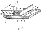
- FIG. 5 shows a glazing 70 fitted with a frame made up of two elements.
- the glazing is presented installed in the body bay.
- the elastomer frame has a first external part 71 which encases the edge of the glazing and a second section 75 placed along the first and directed towards the interior of the glazing which itself has the U-shaped structure.
- the frame 71 has, here , at its periphery a rib 72 directed towards the sheet 80 of the bodywork bay.
- the frame 71 is obtained by an encapsulation technique carried out at the periphery of the glazing 70.
- the profile 75 is deposited by extrusion using a calibrated nozzle.
- the two lateral wings 76 and 77 of this latter profile 75 are each equipped on their internal face with longitudinal ribs intended to allow mechanical attachment. It is these ribs which, in the case of total encapsulation, would cause problems with demolding.
- the installation adhesive is deposited in the internal channel of the profile 75.
- the glazing fitted on the one hand with its double elastomer frame, and on the other hand with the bead of laying adhesive is placed in the bay of the bodywork, the adhesive adheres to the sheet 80.
- the laying adhesive does not adhere to the elastomer constituting the U-shaped profile. It is only because the internal part of the U which widens downwards comprises the suitable ribs that the hardened adhesive allows mechanical attachment between the sheet and the glass by means of the installation adhesive and the elastomer deposited on the glass.
- the glazing thus prepared is placed in the half-mold lower provided for encapsulation.
- the upper half-mold is then put in place and the assembly closed in a sealed manner on the glass.
- a polymer is then injected under pressure under conditions suitable for quality encapsulation. If it is a thermoplastic elastomer, it is at the temperature which allows injection. This temperature is such that after demolding the glazing itself is generally at least at a temperature of 80 ° C. If the encapsulation has been done cold, the glass is reheated.
- the glazing which is then fitted with the demoulded outer frame 71 is transferred to a work table generally situated near the encapsulation station. As soon as it is in position, the profile 75 is extruded under the usual conditions.
Abstract
Description
L'invention concerne un vitrage pour le montage par collage sur la tôle d'une baie en particulier un vitrage automobile comportant un profilé en forme de cadre à sa périphérie, profilé qui comporte une section en U dirigée vers la tôle de la baie et est constitué d'un polymère, le profilé comportant de part et d'autre du U deux ailes équipées vers l'intérieur de nervures servant à l'accrochage du cordon de colle placé à l'intérieur dudit U et le procédé pour le fabriquer.The invention relates to a glazing for mounting by gluing on the sheet of a bay, in particular an automotive glazing comprising a frame-shaped profile at its periphery, a profile which has a U-shaped section directed towards the sheet of the bay and is made of a polymer, the profile comprising on either side of the U two wings fitted inwards with ribs used for hanging the bead of adhesive placed inside said U and the method for manufacturing it.
Un vitrage du type précédent est connu par le document EP-B-0 258 128. Dans ce document la liaison entre le vitrage prééquipé et la tôle de la baie de la fenêtre se fait essentiellement grâce à une liaison adhésive entre la colle et le profilé polymérisé en forme de cadre. La structure de la partie creuse du profilé avec ses nervures longitudinales a pour fonction dans ce cas d'améliorer encore la liaison entre la colle de pose et le polymère du profilé. Ce sont les nervures longitudinales qui produisent l'accrochage mécanique supplémentaire entre le profilé polymérisé et la colle. Le profilé polymérisé en forme de cadre est constitué dans le vitrage connu de polyuréthane soit avec un système monocomposant qui durcit à l'humidité soit avec un système à deux composants qui réagissent immédiatement après leur mélange au moment de l'extrusion sur le vitrage.Glazing of the above type is known from document EP-B-0 258 128. In this document the connection between the pre-fitted glazing and the sheet metal of the window opening is essentially made by an adhesive bond between the glue and the profile. polymerized in the form of a frame. The structure of the hollow part of the profile with its longitudinal ribs has the function in this case of further improving the connection between the laying adhesive and the polymer of the profile. These are the longitudinal ribs which produce the additional mechanical attachment between the polymerized profile and the adhesive. The frame-shaped polymerized profile is formed in the known glazing of polyurethane either with a single-component system which cures with moisture or with a two-component system which react immediately after their mixing upon extrusion on the glazing.
Grâce à ce document il est également connu de diminuer volontairement l'adhésion entre le profil polymérisé et la colle de pose ou même de l'empêcher totalement de telle manière que la liaison ne soit assurée que par l'accrochage mécanique procuré par la forme de la partie commune au profilé et à la colle de montage. On obtient dans ce cas la diminution ou la suppression de la liaison adhésive entre les deux par l'interposition d'un matériau intermédiaire ad hoc.Thanks to this document it is also known to reduce voluntarily adhesion between the polymerized profile and the laying adhesive or even to prevent it completely in such a way that the connection is only ensured by the mechanical attachment provided by the shape of the part common to the profile and to the adhesive mounting. In this case, the adhesive bond between the two is reduced or eliminated by the interposition of an ad hoc intermediate material.
L'état de la technique antérieure permet de situer la mission que se donne l'invention dans le fait de trouver une combinaison de matériaux pour le profilé polymérisé d'une part et pour la colle de pose de l'autre telle qu'elle permette d'une part sans l'interposition d'un autre matériau d'éviter l'adhésion entre les deux matériaux tout en garantissant une excellente tenue mécanique de l'un par rapport à l'autre.The state of the prior art makes it possible to situate the mission that the invention gives itself in finding a combination of materials for the polymerized profile on the one hand and for the laying adhesive on the other as it allows on the one hand without the interposition of another material to avoid adhesion between the two materials while ensuring excellent mechanical strength of one with respect to the other.
L'invention se donne également pour tâche de permettre un durcissement rapide de la colle de pose de manière à permettre, en cas de nécessité, un démontage du vitrage qu'on vient de poser, peu de temps après son installation dans la baie.The invention also gives itself the task of allowing rapid hardening of the laying adhesive so as to allow, if necessary, disassembly of the glazing which has just been installed, shortly after its installation in the bay.
L'invention propose, pour atteindre ce but un vitrage du type divulgué dans EP-A-0 258 128 tel que défini dans le préambule de la revendication 1; ce vitrage étant caractérisé par le fait d'avoir d'une part un profilé en forme de cadre à base d'un élastomère polyoléfine thermoplastique fait d'un polypropylène isotactique et d'un caoutchouc éthylène-propylène-diène et de l'autre une colle à base d'un système de polyuréthane monocomposant polymérisant à l'humidité.The invention proposes, to achieve this object a glazing of the type disclosed in EP-A-0 258 128 as defined in the preamble of claim 1; this glazing being characterized by having on the one hand a frame-shaped profile based on a thermoplastic polyolefin elastomer made of an isotactic polypropylene and an ethylene-propylene-diene rubber and on the other a glue based on a one-component polyurethane system which cures with humidity.
Selon l'invention des vitrages prééquipés peuvent être montés sans aucune préparation supplémentaire grâce aux méthodes traditionnelles de collage. Il suffit qu'après avoir déposé un cordon de la colle de pose à l'intérieur du profilé en U on pose l'ensemble dans la baie. Après durcissement de la colle, le vitrage peut être à tout moment extrait de sa feuillure grâce à une simple pression. Lors de cette opération, les côtés du profilé en U se déforment et s'écartent de la colle durcie.According to the invention pre-equipped glazing can be fitted without any additional preparation thanks to traditional bonding methods. It is sufficient that after having deposited a bead of installation adhesive inside the U-shaped profile, the assembly is placed in the bay. After the glue has hardened, the glazing can be removed from its rebate at any time by simply pressing it. During this operation, the sides of the U-profile are deformed and move away from the hardened adhesive.
Plus tard le vitrage démonté peut être de nouveau utilisé et monté à nouveau. Pour réaliser cette opération on commence par enlever la colle durcie qui adhère à la carrosserie puis l'on procède comme lors de la première monte.Later the dismantled glazing can be used again and mounted again. To perform this operation we start by removing the hardened glue which adheres to the bodywork then we proceed as during the original assembly.
Cette technique de pose de vitrage est particulièrement avantageuse dans le cas des vitrages automobiles car elle permet de démonter simplement un vitrage qui vient d'être posé tout en autorisant sa réutilisation ultérieure. Ainsi lorsqu'on doit faire un raccord de peinture sur une carrosserie, dans le voisinage d'un pare-brise par exemple, on peut effectuer toutes les opérations de retouche après avoir démonté le vitrage. Il suffit à la fin de l'opération de procéder à la pose comme la première fois. De même à la fin de la vie d'une automobile il est très facile de séparer les vitrages de la tôle peinte de manière à procéder à leurs recyclages respectifs.This glazing installation technique is particularly advantageous in the case of automotive glazing because it allows to simply dismantle a glazing which has just been installed while allowing its subsequent reuse. So when you have to make a paint connection on a body, in the vicinity of a windshield for example, you can perform all touch-up operations after dismantling the glazing. It is enough at the end of the operation to proceed with the installation as the first time. Likewise at the end of the life of an automobile, it is very easy to separate the glazing from the painted sheet metal so as to recycle them.
Comme élastomère polyoléfine thermoplastique à base de polypropylène isotactique et de caoutchouc éthylène-propylène-diène (EPDM), on utilisera avantageusement le produit SANTOPRENE A, type 111-64 de la Société Advanced-Elastomer-Systems. Comme colle de pose le produit BETASEAL de la Société Gurit-Essex s'est montré particulièrement intéressant. La combinaison de ces deux matériaux fournit des propriétés mécaniques à l'ensemble, particulièrement satisfaisantes ainsi que des conditions d'adhérence entre eux adaptées au problème.As a thermoplastic polyolefin elastomer based on isotactic polypropylene and ethylene-propylene-diene rubber (EPDM), the product SANTOPRENE A, type 111-64 from the company Advanced-Elastomer-Systems, will advantageously be used. As a laying adhesive, the BETASEAL product from Gurit-Essex was particularly interesting. The combination of these two materials provides particularly satisfactory mechanical properties to the assembly as well as conditions of adhesion between them adapted to the problem.
Dans ce qui suit on présente des exemples de réalisation de l'invention illustrés par les dessins.In what follows, examples of embodiment of the invention are illustrated by the drawings.
Parmi les figures :
- la figure 1 montre un vitrage automobile prééquipé d'un profilé polymérisé collé sur le verre d'un seul côté.
- la figure 2 illustre le procédé de fabrication du vitrage de la figure 1.
- la figure 3 montre un vitrage équipé d'un cadre profilé emprisonnant le chant du verre.
- sur la figure 4 on montre un dispositif destiné à revêtir le creux du profilé en U avec un dépôt contenant de l'humidité,
- et la figure 5 montre un vitrage équipé d'un cadre profilé en deux parties.
- Figure 1 shows a car window pre-equipped with a polymerized profile glued to the glass on one side.
- FIG. 2 illustrates the method of manufacturing the glazing of FIG. 1.
- FIG. 3 shows a glazing unit fitted with a profiled frame trapping the edge of the glass.
- FIG. 4 shows a device intended to coat the hollow of the U-shaped section with a deposit containing moisture,
- and Figure 5 shows a glazing unit fitted with a profiled frame in two parts.
Sur la figure 1 on voit un vitrage automobile prééquipé pour le montage direct par collage dans la baie d'une automobile. Le vitrage 1 est pourvu d'un cadre polymérisé 2 déposé d'un seul côté du verre par extrusion. Le dispositif pour produire un tel vitrage est représenté figure 2.In Figure 1 we see a car window pre-equipped for direct mounting by gluing in the bay of an automobile. The glazing 1 is provided with a polymerized frame 2 deposited on one side of the glass by extrusion. The device for producing such glazing is shown in FIG. 2.
Le vitrage représenté figure 1 est équipé du côté destiné à être placé vis-à-vis de la tôle de la carrosserie d'un dépôt 3 en forme de cadre fait d'un émail cuit à chaud. Après dépôt sur le cadre 3 d'un primaire adapté, on dépose le profilé 2 par extrusion sur l'émail 3. Le profil 2 a une section qui comporte essentiellement une forme de U avec un fond 5 et deux ailes 6 et 7. Le profilé 2 est équipé par ailleurs d'une lèvre 8 qui remplit des fonctions d'étanchéité et de centrage.The glazing shown in FIG. 1 is equipped on the side intended to be placed opposite the sheet metal of the bodywork with a
Le profil 2 est fait d'une matière thermoplastique constituée essentiellement d'un élastomère polyoléfine à base de polypropylène isotactique et de caoutchouc éthylène-propylène-diène (EPDM). Un produit qui convient parfaitement est le SANTOPRENE de la Société Advanced-Elastomer-System. Le primaire déposé sur la couche d'émail 3 est avantageusement constitué d'un système polyuréthane à deux composants modifié dans un solvant. Celui-ci peut être un mélange de trichloréthylène et de 1,1,1 - trichloréthane et de chlorure de méthylène. Ce sont par exemple les produits X-8310 de la Société Henkel ou AK-920 de Koemmerling.Profile 2 is made of a thermoplastic material consisting essentially of a polyolefin elastomer based on isotactic polypropylene and ethylene-propylene-diene rubber (EPDM). A product which is perfectly suited is the SANTOPRENE from the Advanced-Elastomer-System Company. The primer deposited on the
Les ailes latérales 6 et 7 du profilé possèdent des nervures longitudinales. L'espace interne du profilé limité par les ailes latérales s'élargit vers le bas, il prend ainsi la forme d'un sapin de noël. Lors de la pose du vitrage on remplit cet espace interne avec la colle de pose 10. Ce sera par exemple le produit Bétaseal de Gurit-Essex. Cette colle destinée à adhérer sur la tôle 38 qui limite la baie de la carrosserie a la caractéristique de n'établir aucun lien adhésif avec le profilé 2. La conséquence en est qu'il n'y a pas collage entre la colle et le profilé et que l'assemblage ne tiendra après durcissement de la colle que grâce à un accrochage mécanique entre la colle durcie 10 et le profilé 2. La colle 10 est déposée dans le creux du profilé 2 à l'aide d'une buse de telle manière qu'elle remplisse complètement le creux du profilé et que par ailleurs elle déborde sous la forme d'une excroissance 11. Celle-ci constitue la réserve de colle qui permettra la fixation par collage de l'ensemble du vitrage automobile dans la baie.The
Sur la figure 2 on retrouve le vitrage 1 placé avec précision sur un support 13 pour permettre le dépôt du cadre en polymère 2. Le vitrage 1 est chauffé jusqu'à une température de 70 à 90°C. Le robot 15 comporte un bras et une "main" 14. Celle-ci est équipée d'une buse d'extrusion 16. La buse possède un orifice 17 calibré qui permet d'extruder le profilé 2 avec la section voulue.In Figure 2 we find the glazing 1 placed precisely on a support 13 to allow the deposition of the polymer frame 2. The glazing 1 is heated to a temperature of 70 to 90 ° C. The
La buse d'extrusion 16 est déplacée par le robot 15 au bord du vitrage 1 selon un programme prévu à l'avance. Les commandes sont fournies par un processeur 19 par l'intermédiaire des liaisons 20. La buse d'extrusion 16 est équipée d'un élément de chauffage 21 de manière à maintenir la matière à extruder à une température d'environ 200°C, température nécessaire pour permettre l'extrusion dans de bonnes conditions.The
La matière à extruder se présente sous forme de granulés, on les introduit dans la trémie 23 d'où ils sont introduits dans l'extrudeuse à vis 24 où ils sont fondus et conduits sous pression à la tête d'extrusion 16. Le cylindre 25 de l'extrudeuse 24 qui contient une vis sans fin est chauffé grâce à plusieurs anneaux chauffants 26. Ce système permet de maintenir à une température homogène tous les éléments de l'extrudeuse. Le moteur 27 qui anime la vis 24 est commandé, tout comme le robot 15, par le processeur 19.The material to be extruded is in the form of granules, they are introduced into the
La liaison entre le cylindre 25 de l'extrudeuse 24 et la buse d'extrusion 16 se fait grâce à un tuyau chauffant 30 capable de supporter de hautes pressions. Le tuyau chauffant 30 doit en effet supporter des pressions pouvant atteindre 250 bars. Il comporte des résistances chauffantes 31 qui garantissent que le tuyau 30 se trouve à une température de l'ordre de 200°C.The connection between the
Par ailleurs, ce tuyau 30 doit être suffisamment flexible pour pouvoir autoriser le déplacement de la buse 16 sans limitation lors de l'extrusion que le robot 15 effectue à la périphérie du vitrage 1.Furthermore, this
Le tuyau haute pression 30 possède naturellement une certaine résistance à la torsion qui pourrait éventuellement être gênante lors de l'extrusion. En effet, lorsque la "main" 14 du robot a effectué une rotation de 360° autour du vitrage, cette "main" a elle-même tourné de 360° par rapport à l'autre extrémité du tuyau 30. Pour éviter une détérioration du tuyau, on l'équipe d'un ou plusieurs joints tournants 32.The
Sur la figure 3, le vitrage 34 prééquipé selon l'invention possède cette fois un cadre 35 en polymère obtenu par une technique d'encapsulation c'est-à-dire par moulage haute pression. On voit que dans ce cas le vitrage 34 est enchâssé dans son cadre en élastomère 35. Ce cadre 35 est équipé d'une lèvre débordante 36. Lorsque le vitrage est posé, la lèvre 36 s'appuie sur la feuillure 37 du cadre de la fenêtre et obture ainsi l'espace laissé libre entre le vitrage et la carrosserie. Cette lèvre qui occupe en général toute la périphérie du vitrage permet également à celui-ci de se centrer automatiquement dans la baie lors de la pose. La tôle 38 de la baie qui se trouve vis-à-vis du bord du vitrage et sensiblement parallèle à lui est utilisée pour le collage du vitrage prééquipé dans la baie. Le cadre profilé 35 possède en face de la tôle 38 une section en U 39 dont les ailes latérales 40, 41 sont équipées de nervures longitudinales sur leurs faces internes. La largeur du U décroît de sa base vers ses extrémités. Le creux est rempli de la colle de pose 42. Les matériaux utilisés respectivement pour constituer le cadre encapsulé 35 et la colle de pose 42 sont les mêmes que ceux qui ont été décrits lors de la description de la figure 1.
Sur la figure 3, on voit comment l'excroissance de la colle de pose qui a été déposée à l'intérieur du creux du profilé en U s'écrase pour venir adhérer à la tôle 38 de la baie. C'est sous cette forme qu'elle va durcir pour alors assurer un accrochage mécanique entre le cadre profilé 35 et la baie de la carrosserie sur laquelle elle adhère.In Figure 3, the
In FIG. 3, it can be seen how the protuberance of the laying adhesive which has been deposited inside the hollow of the U-shaped profile is crushed so as to adhere to the
Lors de la pose dans la carrosserie du vitrage 1, 34, prééquipé de son cadre profilé 7, 35, 39, on dépose la masse de la colle de pose dans le creux du U du profilé en élastomère thermoplastique. On a vu que cette colle était de préférence constituée d'une matière plastique qui polymérise par suite d'une réaction avec l'humidité. Si la seule humidité disponible est l'humidité de l'air la polymérisation peut être très longue. En effet, comme on le voit figure 3 les surfaces de contact entre le cordon de colle de pose 42 et l'atmosphère ambiante sont très limitées. Cependant, dans de nombreux cas, il peut être intéressant que la prise de colle s'effectue rapidement de manière à ce que par exemple on puisse démonter le pare-brise pour effectuer à son voisinage une retouche à la peinture de la carrosserie.During the installation in the body of the
Pour raccourcir les durées nécessaires au durcissement de la colle de pose on a prévu dans le cadre de l'invention de déposer sur les surfaces internes du profilé en U au moins partiellement une couche qui contient de l'humidité ou des ions hydroxyles.In order to shorten the durations necessary for the hardening of the laying adhesive, it has been provided in the context of the invention to deposit on the internal surfaces of the U-shaped profile at least partially a layer which contains moisture or hydroxyl ions.
Ainsi l'humidité nécessaire à la prise de la colle de pose ne provient plus seulement de l'atmosphère environnant le cordon de colle mais provient également des surfaces de contact avec le profilé en élastomère thermoplastique. On peut grâce au choix de la matière de la couche et/ou grâce au choix de la fraction de la surface interne du U traitée, maîtriser les paramètres de la prise de la colle. Il est en effet important que la prise soit le plus rapide possible une fois le vitrage posé dans la carrosserie mais il est cependant nécessaire qu'elle soit suffisamment lente au niveau de la partie débordante du cordon de colle de pose pour que le durcissement ne soit pas effectué avant la mise en contact avec la tôle pour qu'elle puisse adhérer correctement à la carrosserie.Thus the humidity necessary for the setting of the glue of installation no longer comes only from the atmosphere surrounding the adhesive bead but also comes from the contact surfaces with the thermoplastic elastomer profile. Thanks to the choice of the material of the layer and / or thanks to the choice of the fraction of the internal surface of the treated U, control the parameters of the setting of the glue. It is indeed important for the setting to be as rapid as possible once the glazing has been installed in the bodywork, but it is however necessary that it be sufficiently slow at the level of the projecting part of the bead of laying adhesive so that hardening is not not made before contacting the sheet so that it can adhere properly to the body.
Les produits qui peuvent être utilisés sous forme de couches déposées sur la surface interne du U peuvent être par exemple des substances qui contiennent de l'eau et/ou des groupes hydroxyles comme les hydrates de carbone ou les alcools polyvinyliques. On a eu d'excellents résultats avec par exemple la méthylcellulose ou des dérivés cellulosés. L'effet de la rétention et de la libération de l'eau peut être selon les besoins amélioré par l'addition de sels hydrophiles ou hygroscopiques.The products which can be used in the form of layers deposited on the internal surface of the U can be for example substances which contain water and / or hydroxyl groups such as carbohydrates or polyvinyl alcohols. Excellent results have been obtained with, for example, methylcellulose or cellulose derivatives. The effect of water retention and release can be improved as needed by the addition of hydrophilic or hygroscopic salts.
L'opération de dépôt d'une couche d'un matériau qui retient l'eau sur les parois internes du U du profilé en élastomère thermoplastique peut être effectuée à n'importe quel moment. Il est cependant préférable qu'elle suive immédiatement l'extrusion ou l'encapsulation du cadre profilé en élastomère thermoplastique.The operation of depositing a layer of a material which retains water on the internal walls of the U of the thermoplastic elastomer profile can be carried out at any time. It is however preferable that it immediately follow the extrusion or the encapsulation of the profiled frame of thermoplastic elastomer.
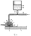
La figure 4 montre un exemple de réalisation du dépôt d'une telle couche. Elle montre une coupe du vitrage 1 qui est équipé à sa périphérie d'un cadre émaillé 3 et d'un cadre profilé 2 obtenu par extrusion directe sur l'émail 3. Le cadre profilé 2 pourrait aussi bien être obtenu par une technique d'encapsulation par moulage sous pression. De même, le cadre au lieu de n'être posé que sur l'une des surfaces du vitrage pourrait l'enchâsser. Le creux à l'intérieur du profilé 2 en U est constitué par les faces internes des deux ailes latérales 6 et 7 et par le fond 5. Conformément à l'invention les faces internes des ailes latérales 6 et 7 comportent des nervures longitudinales.FIG. 4 shows an exemplary embodiment of the deposition of such a layer. It shows a section of the glazing 1 which is equipped at its periphery with an
Dès que le profilé 2 a été complètement déposé à la périphérie du vitrage et alors que sa température est encore comprise entre 150 et 200°C on dépose à l'aide d'un pistolet 60 une solution aqueuse de méthylcellulose à l'intérieur du U. Ce dépôt peut être effectué tout comme l'extrusion du profilé 2 lui-même grâce à un robot qui dirige le pistolet 60. Il est même prévu que les deux outils, buse d'extrusion d'une part et pistolet de pulvérisation de l'autre puissent se succéder tout en étant entraîné simultanément par la "main" du robot.As soon as the profile 2 has been completely deposited on the periphery of the glazing and while its temperature is still between 150 and 200 ° C., an aqueous methylcellulose solution is deposited using a
Des solutions convenant à une pulvérisation pour déposer la couche contenant de l'eau ou des ions OH à la surface de l'intérieur du U du profilé 2 étaient constituées par exemple de 96 parties d'eau et de 4 parties de méthylcellulose ou bien de 95 parties d'eau, de 4 parties de méthylcellulose et d'une partie de sel marin.Solutions suitable for spraying to deposit the layer containing water or OH ions on the surface of the interior of the U of the profile 2 consisted for example of 96 parts of water and 4 parts of methylcellulose or else 95 parts of water, 4 parts of methylcellulose and one part of sea salt.
Dans l'exemple de réalisation de la figure 4 on souffle de l'air dans le canal 61 qui conduit au pistolet 60. Ce canal 61 est relié à la sortie d'un réservoir 62 où est stockée une quantité importante 63 de la solution aqueuse de méthylcellulose. Par effet venturi, le courant d'air dans le canal 61 extrait la solution à la sortie de la vanne 64. Cette vanne permet de réguler le débit. Le brouillard de liquide qui sort du pistolet 60 est projeté sur les parois internes du U où il constitue un dépôt 65. Du fait qu'au moment de la pulvérisation de la solution le matériau du profilé 2 est encore à une température relativement élevée le séchage du dépôt s'effectue rapidement. La méthylcellulose, après séchage, est capable d'attirer et d'intégrer l'humidité de l'air environnant. Plus tard, cette humidité stockée dans le couche de méthylcellulose suffit, lorsqu'elle entre en contact avec la matière de la colle de pose déposée dans la partie creuse du U, pour provoquer son durcissement rapide.In the embodiment of FIG. 4, air is blown into the
Par comparaison avec les techniques d'extrusion, l'utilisation d'une méthode d'encapsulation par moulage haute pression pour déposer le profilé périphérique en élastomère thermofusible nécessite des moules spéciaux adaptés, ce qui complique l'opération d'encapsulation. En revanche l'encapsulation comparée à l'extrusion permet de donner au profilé des formes plus variées en particulier l'encapsulation permet la réalisation d'un joint périphérique qui entoure le chant du vitrage.Compared with extrusion techniques, the use of an encapsulation method by high pressure molding to deposit the peripheral profile in hot-melt elastomer requires molds special adapted, which complicates the encapsulation operation. On the other hand, the encapsulation compared to the extrusion makes it possible to give the profile more varied forms, in particular the encapsulation allows the production of a peripheral seal which surrounds the edge of the glazing.
La figure 5 montre un vitrage 70 équipé d'un cadre constitué de deux éléments. Le vitrage est présenté installé dans la baie de carrosserie. Le cadre en élastomère comporte une première partie externe 71 qui enchâsse le bord du vitrage et un deuxième profilé 75 placé le long du premier et dirigé vers l'intérieur du vitrage qui possède, lui, la structure en U. Le cadre 71 possède, ici, à sa périphérie une nervure 72 dirigée vers la tôle 80 de la baie de carrosserie. Le cadre 71 est obtenu par une technique d'encapsulation réalisée à la périphérie du vitrage 70. En revanche, le profilé 75 est déposé, lui, par extrusion à l'aide d'une buse calibrée. Les deux ailes latérales 76 et 77 de ce dernier profil 75 sont équipées chacune sur leur face interne de nervures longitudinales destinées à permettre l'accrochage mécanique. Ce sont ces nervures qui dans le cas d'une encapsulation totale poseraient des problèmes au démoulage. Lorsque le vitrage est prêt à la pose, on dépose dans le canal interne du profilé 75 la colle de pose. Lorsque le vitrage équipé d'une part de son double cadre en élastomère, d'autre part du cordon de la colle de pose, est placé dans la baie de la carrosserie, la colle adhère à la tôle 80. En revanche, dans la mesure où les matériaux sont ceux qui ont été décrits plus haut, la colle de pose n'adhère pas à l'élastomère constituant le profilé en U. C'est seulement parce que la partie interne du U qui s'élargit vers le bas comporte les nervures adaptées que la colle durcie permet un accrochage mécanique entre la tôle et le verre par l'intermédiaire de la colle de pose et de l'élastomère déposé sur le verre.FIG. 5 shows a
Pour réaliser le cadre représenté figure 5, on procède de la manière suivante : le vitrage 70 qui a été équipé de manière connue lors de sa fabrication, d'un cadre en émail 81 qui est opaque est d'abord revêtu d'une couche de primaire 82 et cela sur toutes les surfaces qui seront en contact avec le cadre. Il est intéressant d'utiliser pour ce primaire un produit qui convienne aussi bien à l'adhérence du polymère d'encapsulation qu'à l'élastomère thermoplastique d'extrusion. Dans le cas où tous deux sont constitués du même élastomère thermoplastique les primaires qui ont été cités plus haut conviennent.To make the frame shown in Figure 5, we proceed as follows: the glazing 70 which was fitted in a known manner during its manufacture, an
Le vitrage ainsi préparé est placé dans le demi-moule inférieur prévu pour l'encapsulation. Le demi-moule supérieur est alors mis en place et l'ensemble fermé de manière étanche sur le verre. On injecte ensuite sous pression un polymère dans les conditions adaptées à une encapsulation de qualité. S'il s'agit d'un élastomère thermoplastique il est à la température qui permet l'injection. Cette température est telle qu'après démoulage le vitrage lui-même est en général au moins à une température de 80°C. Si l'encapsulation a été faite à froid, on réchauffe le verre. Le vitrage qui est alors équipé du cadre extérieur 71 démoulé est transféré sur une table de travail située en général près du poste d'encapsulation. Dès qu'il est en position on procède à l'extrusion du profilé 75 dans les conditions habituelles.The glazing thus prepared is placed in the half-mold lower provided for encapsulation. The upper half-mold is then put in place and the assembly closed in a sealed manner on the glass. A polymer is then injected under pressure under conditions suitable for quality encapsulation. If it is a thermoplastic elastomer, it is at the temperature which allows injection. This temperature is such that after demolding the glazing itself is generally at least at a temperature of 80 ° C. If the encapsulation has been done cold, the glass is reheated. The glazing which is then fitted with the demoulded
Claims (7)
- Pane for mounting by gluing onto the surrounding sheet of a window opening, in particular automobile pane, comprising a frame-shaped profile at its periphery, which profile possesses a U-section facing towards the sheeting of the window opening and is constituted of a polymer, the profile possessing two flanges provided, towards the interior of the U, with ribs serving for gripping the positioning adhesive cord which hardens in place in the U-shaped channel during the positioning of the pane and the bonding of the adhesive to the window opening, the profile and the adhesive not exhibiting any bond to one another so that the connection between the profile and the hardened adhesive is purely of a mechanical nature due to the shape, characterized in that the frame-shaped profile is at least partly, in the zone with a U-shaped section, based upon a thermoplastic polyolefin elastomer made of an isotactic polypropylene and an ethylene-propylene-diene rubber, and in that the positioning adhesive is based upon a single-component polyurethane system polymerizing with humidity.
- Pane according to claim 1, characterized in that the interior of the U-section of the frame-shaped profile has the shape of a Christmas tree.
- Pane according to claim 1 or 2, characterized in that the internal surface of the U of the frame-shaped profile which comes into contact with the positioning adhesive is provided, at least partly, with a film that contains humidity and/or hydroxyl ions.
- Pane according to claim 3, characterized in that the film that contains humidity and/or hydroxyl ions is constituted of a carbohydrate of high molecular weight and/or a polyvinyl alcohol.
- Pane according to claim 3, characterized in that the film that contains humidity and/or hydroxyl ions is based upon methyl cellulose.
- Pane according to one of claims 3 to 5, characterized in that the film that contains humidity and/or hydroxyl ions comprises, in addition, a hydrophilic or hygroscopic salt.
- Method of making a pane according to one of claims 3 to 6, characterized in that the frame-shaped profile which has a U-section is deposited on the pane and in that, immediately after this deposition while the profile is still hot, the solution making possible the production of the film that contains humidity and/or hydroxyl ions is deposited.
Priority Applications (1)
| Application Number | Priority Date | Filing Date | Title |
|---|---|---|---|
| EP97104468A EP0785058B1 (en) | 1993-01-16 | 1994-01-13 | Method and device for the fabrication of a vehicle glazing preassembled in order to be glued in an opening |
Applications Claiming Priority (6)
| Application Number | Priority Date | Filing Date | Title |
|---|---|---|---|
| DE4301026A DE4301026A1 (en) | 1993-01-16 | 1993-01-16 | Vehicle window pane |
| DE4301026 | 1993-01-16 | ||
| DE4302981A DE4302981A1 (en) | 1993-01-16 | 1993-02-03 | Auto-glass pane pre-finished for adhesive bonding with a window frame and process for producing it |
| DE4302981 | 1993-02-03 | ||
| DE4311584 | 1993-04-08 | ||
| DE4311584A DE4311584A1 (en) | 1993-01-16 | 1993-04-08 | Process for producing a pane of glass provided with a frame structure suitable for adhesive fitting |
Related Child Applications (1)
| Application Number | Title | Priority Date | Filing Date |
|---|---|---|---|
| EP97104468.0 Division-Into | 1997-03-15 |
Publications (3)
| Publication Number | Publication Date |
|---|---|
| EP0620134A2 EP0620134A2 (en) | 1994-10-19 |
| EP0620134A3 EP0620134A3 (en) | 1995-01-25 |
| EP0620134B1 true EP0620134B1 (en) | 1997-11-05 |
Family
ID=27204661
Family Applications (2)
| Application Number | Title | Priority Date | Filing Date |
|---|---|---|---|
| EP97104468A Expired - Lifetime EP0785058B1 (en) | 1993-01-16 | 1994-01-13 | Method and device for the fabrication of a vehicle glazing preassembled in order to be glued in an opening |
| EP94400086A Expired - Lifetime EP0620134B1 (en) | 1993-01-16 | 1994-01-13 | Vehicle glazing preassembled in order to be glued in an opening and method for its manufacture |
Family Applications Before (1)
| Application Number | Title | Priority Date | Filing Date |
|---|---|---|---|
| EP97104468A Expired - Lifetime EP0785058B1 (en) | 1993-01-16 | 1994-01-13 | Method and device for the fabrication of a vehicle glazing preassembled in order to be glued in an opening |
Country Status (13)
| Country | Link |
|---|---|
| US (2) | US5723196A (en) |
| EP (2) | EP0785058B1 (en) |
| JP (1) | JPH06320944A (en) |
| KR (1) | KR100296212B1 (en) |
| AT (2) | ATE218427T1 (en) |
| CA (1) | CA2113386A1 (en) |
| CZ (1) | CZ286396B6 (en) |
| DE (2) | DE69430759T2 (en) |
| ES (2) | ES2110702T3 (en) |
| FI (1) | FI940207A (en) |
| PL (1) | PL175008B1 (en) |
| PT (1) | PT785058E (en) |
| TW (1) | TW302351B (en) |
Cited By (2)
| Publication number | Priority date | Publication date | Assignee | Title |
|---|---|---|---|---|
| DE20006330U1 (en) * | 2000-04-07 | 2001-05-23 | Bbg Braunsberger Gmbh & Co Kg | Glass pane with plastic edging |
| US6890468B2 (en) | 1999-05-24 | 2005-05-10 | Societa Italiana Vetro-Siv-S.P.A. | Method for molding a glazing profile on a sheet of glazing material |
Families Citing this family (49)
| Publication number | Priority date | Publication date | Assignee | Title |
|---|---|---|---|---|
| CA2113386A1 (en) * | 1993-01-16 | 1994-07-17 | Gerd Cornils | Vehicle window glass equipped for glucing in an opening and manufacturing process therefor |
| DE19503314C1 (en) * | 1995-02-02 | 1996-06-20 | Sekurit Saint Gobain Deutsch | Glass screen, esp. for use in motor vehicles |
| DE19537693C1 (en) * | 1995-10-10 | 1996-10-02 | Sekurit Saint Gobain Deutsch | Glass panel mfr. for a thermoplastic elastomer profiled frame |
| EP0825052B1 (en) * | 1996-08-22 | 2000-10-18 | Volkswagen Aktiengesellschaft | Fixing arrangement of a window pane in a motor vehicle |
| JP4460078B2 (en) * | 1996-10-17 | 2010-05-12 | サン−ゴバン グラス フランス | Glazing assembly |
| DE19649617A1 (en) * | 1996-11-29 | 1998-06-04 | Henniges Elastomer Kunststoff | Method for producing a connection between a component and a component |
| FR2770212B1 (en) | 1997-10-29 | 1999-11-26 | Eurokera | GLASS MATERIAL PLATE FOR FIXING IN A FRAME |
| DE19802203A1 (en) * | 1998-01-22 | 1999-08-05 | Henniges Elastomer Kunststoff | Method for producing a connection between a component and a component |
| DE19843843C2 (en) | 1998-09-24 | 2001-08-30 | Saint Gobain Sekurit D Gmbh | Window pane with a profile strand comprising a gap cover |
| DE19910467C1 (en) * | 1999-03-10 | 2000-10-19 | Schott Glas | Holder and method for producing a holder for essentially flat molded articles made of brittle material |
| DE19912176A1 (en) * | 1999-03-18 | 2000-09-21 | Volkswagen Ag | Sealing arrangement for a component in the manner of a door or flap |
| DE19927473A1 (en) * | 1999-06-16 | 2000-12-21 | Schade Plettenberg Glasmodule | Process for producing and gluing a plastic-coated pane |
| PT1324892E (en) * | 2000-10-10 | 2007-10-22 | Saint Gobain | Use of a glazing comprising a profiled string rim for its installation in a recess |
| US6607622B2 (en) | 2001-02-15 | 2003-08-19 | Centre Luxembourgeois De Recherches Pour Le Verre Et La Ceramique S.A. (C.R.V.C.) | Method of applying an extruded profile to a window glazing |
| JP2002240122A (en) * | 2001-02-21 | 2002-08-28 | Asahi Glass Co Ltd | Method for producing plate with resin frame |
| FR2828191B1 (en) * | 2001-08-06 | 2003-11-14 | Saint Gobain | PROCESS FOR TREATING LAMINATED GLAZING AND APPLICATION |
| WO2004024843A1 (en) * | 2002-08-30 | 2004-03-25 | Asahi Glass Company, Limited | Adhesive composition and glass plate with thermoplastic elastomer molding |
| US20040229017A1 (en) * | 2003-05-14 | 2004-11-18 | Medtronic Midas Rex | Permanent colored markings on medical devices |
| FR2856951B1 (en) * | 2003-07-01 | 2006-06-23 | Saint Gobain | GLAZING COMPRISING A REINFORCING ELEMENT |
| JP2006124985A (en) * | 2004-10-27 | 2006-05-18 | Yokohama Rubber Co Ltd:The | Shaping method for glazing channel for double glazing and its shaping device |
| US7703830B2 (en) * | 2005-05-25 | 2010-04-27 | Dura Global Technologies, Inc. | Window assembly having an integral bonding system |
| GB2432870A (en) * | 2005-11-18 | 2007-06-06 | Gdx North America Inc | Sealing assemblies and methods of making them |
| JP4277920B2 (en) * | 2007-05-25 | 2009-06-10 | トヨタ自動車株式会社 | Weather strip structure |
| FR2921652B1 (en) * | 2007-10-02 | 2014-11-07 | Saint Gobain | METHOD AND APPARATUS FOR PRINTING PUMPS BY PAD PRINTING, GLAZING (S) WITH PRINTING LAYER DEPOSITED BY PADDOGRAPHY AND USE OF A PUSHING DEVICE. |
| KR101678057B1 (en) * | 2010-10-04 | 2016-12-06 | 삼성전자 주식회사 | Patterning mold and manufacturing method thereof |
| DE102014114414A1 (en) * | 2014-10-03 | 2016-04-07 | Bbg Gmbh & Co. Kg | Frame construction for a glass pane and method for its production |
| US10562274B1 (en) * | 2016-02-22 | 2020-02-18 | Apple Inc. | Glass fastening and sealing systems |
| EP3426614A1 (en) | 2016-03-09 | 2019-01-16 | Corning Incorporated | Cold forming of complexly curved glass articles |
| TWI800921B (en) | 2016-06-28 | 2023-05-01 | 美商康寧公司 | Laminating thin strengthened glass to curved molded plastic surface for decorative and display cover application |
| JP7071294B2 (en) | 2016-07-05 | 2022-05-18 | コーニング インコーポレイテッド | Cold-formed glass articles and their assembly methods |
| FR3055639B1 (en) * | 2016-09-08 | 2021-12-10 | Saint Gobain | ELEMENT OF CONSTRUCTION |
| CN110049958B (en) | 2016-10-25 | 2022-07-19 | 康宁公司 | Cold-formed glass laminate for display |
| EP3978237A1 (en) | 2017-01-03 | 2022-04-06 | Corning Incorporated | Kit having a curved glass substrate |
| US11016590B2 (en) | 2017-01-03 | 2021-05-25 | Corning Incorporated | Vehicle interior systems having a curved cover glass and display or touch panel and methods for forming the same |
| KR102558993B1 (en) | 2017-05-15 | 2023-07-24 | 코닝 인코포레이티드 | Contoured glassware and its manufacturing method |
| JP2020533217A (en) | 2017-07-18 | 2020-11-19 | コーニング インコーポレイテッド | Cold molding of intricately curved glass articles |
| CN111183123A (en) | 2017-09-12 | 2020-05-19 | 康宁公司 | Tactile assembly for electroless plate glass and method for producing same |
| TWI806897B (en) | 2017-09-13 | 2023-07-01 | 美商康寧公司 | Light guide-based deadfront for display, related methods and vehicle interior systems |
| US11065960B2 (en) | 2017-09-13 | 2021-07-20 | Corning Incorporated | Curved vehicle displays |
| TW201918462A (en) | 2017-10-10 | 2019-05-16 | 美商康寧公司 | Vehicle interior systems having a curved cover glass with improved reliability and methods for forming the same |
| DE102017220691A1 (en) * | 2017-11-20 | 2019-05-23 | Bayerische Motoren Werke Aktiengesellschaft | Arrangement structure and method for producing a component arrangement |
| WO2019103469A1 (en) | 2017-11-21 | 2019-05-31 | Corning Precision Materials Co., Ltd. | Aspheric mirror for head-up display system and methods for forming the same |
| JP7407707B2 (en) | 2017-11-30 | 2024-01-04 | コーニング インコーポレイテッド | System and method for vacuum forming an aspherical mirror |
| US11550148B2 (en) | 2017-11-30 | 2023-01-10 | Corning Incorporated | Vacuum mold apparatus, systems, and methods for forming curved mirrors |
| CN111989302B (en) | 2018-03-13 | 2023-03-28 | 康宁公司 | Carrier interior systems with crack resistant curved cover glass and methods for forming these carrier interior systems |
| WO2020018284A1 (en) | 2018-07-16 | 2020-01-23 | Corning Incorporated | Vehicle interior systems having a cold-bent glass substrate and methods for forming the same |
| EP3771695A1 (en) | 2019-07-31 | 2021-02-03 | Corning Incorporated | Method and system for cold-forming glass |
| EP3771700A1 (en) * | 2019-08-02 | 2021-02-03 | Corning Incorporated | Cold-formed glass assemblies and methods of making |
| US11772361B2 (en) | 2020-04-02 | 2023-10-03 | Corning Incorporated | Curved glass constructions and methods for forming same |
Family Cites Families (33)
| Publication number | Priority date | Publication date | Assignee | Title |
|---|---|---|---|---|
| GB703873A (en) * | 1951-09-06 | 1954-02-10 | Windshields Of Worcester Ltd | Improved means for glazing vehicle and other windows |
| US3194570A (en) * | 1962-01-29 | 1965-07-13 | Federal Mogul Bower Bearings | Multiple-lip seal |
| US3779794A (en) * | 1970-03-05 | 1973-12-18 | Essex Chemical Corp | Polyurethane sealant-primer system |
| FR2157189A5 (en) * | 1971-10-21 | 1973-06-01 | Peugeot & Renault | Windscreen seals - moulded in situ with the use of a flexible mould which can be dismantled |
| US4155698A (en) * | 1975-04-08 | 1979-05-22 | Albert Obrist Ag | Method and apparatus for injection molding of plastic closures |
| US4235582A (en) * | 1975-10-22 | 1980-11-25 | Professional Packaging Limited | Method and apparatus for molding holders for disc-like objects |
| GB2072568B (en) * | 1980-03-26 | 1983-09-21 | Global Castors & Hardware Ltd | Moulded components |
| US4403004A (en) * | 1981-10-23 | 1983-09-06 | Transfer Print Foils, Inc. | Sandwich metalized resin laminate |
| EP0121480B1 (en) * | 1983-03-31 | 1995-06-14 | Saint-Gobain Vitrage International | Mounting of a pane in an opening by means of adhesives, especially of a vehicle windshield, for an easier removal of it |
| FR2543534B1 (en) * | 1983-03-31 | 1986-08-14 | Saint Gobain Vitrage | IMPROVEMENT IN MOUNTING BY GLUING A GLASS IN A BAY, ESPECIALLY A MOTOR VEHICLE |
| US4551372A (en) * | 1983-03-31 | 1985-11-05 | Saint-Gobain Vitrage | Laminated safety glass |
| JPS6099619A (en) * | 1983-11-07 | 1985-06-03 | Matsushita Electric Ind Co Ltd | Mold assembly |
| US4581276A (en) * | 1984-05-25 | 1986-04-08 | Saint-Gobain Vitrage | Adhesive bonding means for mounting glass sheets in a window aperture |
| DE3500205A1 (en) * | 1985-01-05 | 1986-07-10 | VEGLA Vereinigte Glaswerke GmbH, 5100 Aachen | ADHESIVE CONNECTION FOR GLUING A GLASS PANEL TO A WINDOW FRAME |
| DE3518145A1 (en) * | 1985-05-21 | 1986-11-27 | Elkamet-Werk Lahn-Kunststoff GmbH, 7100 Heilbronn | Window pane, in particular for vehicles |
| US4762481A (en) * | 1985-11-01 | 1988-08-09 | Libbey-Owens-Ford Co. | Mold structure for producing a window assembly |
| US4662113A (en) * | 1985-11-01 | 1987-05-05 | Libbey-Owens-Ford Co. | Window assembly and method of making the same |
| US4834931A (en) * | 1985-11-01 | 1989-05-30 | Libbey-Owens-Ford Co. | Method of making a window assembly |
| JPH0624884B2 (en) * | 1985-12-28 | 1994-04-06 | 日産自動車株式会社 | Corner-moor mounting structure for automobile windmills |
| DE3612923C2 (en) * | 1986-04-17 | 1995-08-17 | Opel Adam Ag | Method for fastening a decorative strip to an adhesive window pane of a motor vehicle |
| DE3618278A1 (en) * | 1986-05-30 | 1987-12-03 | Ver Glaswerke Gmbh | GLASS PANEL WITH PROFILE BAR CLOSED IN THE EDGE AREA |
| DE3627537A1 (en) * | 1986-08-13 | 1988-02-18 | Ver Glaswerke Gmbh | GLASS DISC PROVIDED WITH AN ELASTIC SEALING PROFILE, IN PARTICULAR CAR GLASS DISC |
| DE3627536A1 (en) * | 1986-08-13 | 1988-02-25 | Ver Glaswerke Gmbh | PROVIDED FOR THE DIRECT GLUE, IN PARTICULAR CAR GLASS |
| DE3730345A1 (en) * | 1987-09-10 | 1989-03-30 | Ver Glaswerke Gmbh | MOTOR VEHICLE WINDOW |
| DE3730344A1 (en) * | 1987-09-10 | 1989-03-30 | Ver Glaswerke Gmbh | CAR GLASS PANEL FOR DIRECT GLUE |
| DE3905906C2 (en) * | 1989-02-25 | 1995-03-23 | Gurit Essex Ag | Gap seal for windows, especially for vehicle windows |
| ATE118413T1 (en) * | 1989-09-12 | 1995-03-15 | Saint Gobain Vitrage | GLAZING WITH A PROFILE FRAME, IN PARTICULAR VEHICLE GLAZING, AND METHOD AND DEVICE FOR THE PRODUCTION THEREOF. |
| DE9003934U1 (en) * | 1990-04-04 | 1990-06-07 | Vorwerk & Sohn Gmbh & Co Kg, 5600 Wuppertal, De | |
| DE4031236A1 (en) * | 1990-10-04 | 1992-04-09 | Ver Glaswerke Gmbh | DEVICE FOR SHAPING A PROFILE STRAND BY EXTRUDING DIRECTLY ON THE EDGE OF A GLASS DISC |
| DE4100631A1 (en) * | 1991-01-11 | 1992-07-16 | Ver Glaswerke Gmbh | CAR GLASS DISC PREPARED FOR ASSEMBLY BY GLUE |
| ATE141222T1 (en) * | 1991-07-03 | 1996-08-15 | Gurit Essex Ag | RESOLVABLE ADHESIVE CONNECTIONS, METHOD FOR THE PRODUCTION THEREOF AND USE OF DEVICES FOR RELEASING SUCH ADHESIVE CONNECTIONS |
| US5620794A (en) * | 1992-07-01 | 1997-04-15 | Gurit-Essex Ag | Releasable adhesive joint, a method for establishing a releasable adhesive joint and an apparatus for releasing such adhesive joints |
| CA2113386A1 (en) * | 1993-01-16 | 1994-07-17 | Gerd Cornils | Vehicle window glass equipped for glucing in an opening and manufacturing process therefor |
-
1994
- 1994-01-13 CA CA002113386A patent/CA2113386A1/en not_active Abandoned
- 1994-01-13 DE DE69430759T patent/DE69430759T2/en not_active Expired - Fee Related
- 1994-01-13 ES ES94400086T patent/ES2110702T3/en not_active Expired - Lifetime
- 1994-01-13 ES ES97104468T patent/ES2177848T3/en not_active Expired - Lifetime
- 1994-01-13 AT AT97104468T patent/ATE218427T1/en not_active IP Right Cessation
- 1994-01-13 DE DE69406574T patent/DE69406574T2/en not_active Expired - Fee Related
- 1994-01-13 EP EP97104468A patent/EP0785058B1/en not_active Expired - Lifetime
- 1994-01-13 EP EP94400086A patent/EP0620134B1/en not_active Expired - Lifetime
- 1994-01-13 AT AT94400086T patent/ATE159900T1/en not_active IP Right Cessation
- 1994-01-13 PT PT97104468T patent/PT785058E/en unknown
- 1994-01-14 KR KR1019940000560A patent/KR100296212B1/en not_active IP Right Cessation
- 1994-01-14 PL PL94301899A patent/PL175008B1/en not_active IP Right Cessation
- 1994-01-14 FI FI940207A patent/FI940207A/en not_active Application Discontinuation
- 1994-01-14 CZ CZ199488A patent/CZ286396B6/en not_active IP Right Cessation
- 1994-01-17 JP JP6003187A patent/JPH06320944A/en active Pending
- 1994-01-18 US US08/188,161 patent/US5723196A/en not_active Expired - Fee Related
- 1994-01-24 TW TW083100562A patent/TW302351B/zh active
-
1997
- 1997-10-10 US US08/948,613 patent/US5897937A/en not_active Expired - Fee Related
Cited By (2)
| Publication number | Priority date | Publication date | Assignee | Title |
|---|---|---|---|---|
| US6890468B2 (en) | 1999-05-24 | 2005-05-10 | Societa Italiana Vetro-Siv-S.P.A. | Method for molding a glazing profile on a sheet of glazing material |
| DE20006330U1 (en) * | 2000-04-07 | 2001-05-23 | Bbg Braunsberger Gmbh & Co Kg | Glass pane with plastic edging |
Also Published As
| Publication number | Publication date |
|---|---|
| EP0785058A3 (en) | 1999-06-16 |
| EP0620134A2 (en) | 1994-10-19 |
| PT785058E (en) | 2002-11-29 |
| EP0785058A2 (en) | 1997-07-23 |
| ES2177848T3 (en) | 2002-12-16 |
| JPH06320944A (en) | 1994-11-22 |
| CA2113386A1 (en) | 1994-07-17 |
| KR940018332A (en) | 1994-08-16 |
| TW302351B (en) | 1997-04-11 |
| EP0620134A3 (en) | 1995-01-25 |
| PL175008B1 (en) | 1998-10-30 |
| PL301899A1 (en) | 1994-07-25 |
| CZ286396B6 (en) | 2000-04-12 |
| ATE218427T1 (en) | 2002-06-15 |
| ES2110702T3 (en) | 1998-02-16 |
| FI940207A0 (en) | 1994-01-14 |
| ATE159900T1 (en) | 1997-11-15 |
| KR100296212B1 (en) | 2001-11-30 |
| US5723196A (en) | 1998-03-03 |
| DE69406574T2 (en) | 1998-05-07 |
| FI940207A (en) | 1994-07-17 |
| DE69406574D1 (en) | 1997-12-11 |
| US5897937A (en) | 1999-04-27 |
| EP0785058B1 (en) | 2002-06-05 |
| CZ8894A3 (en) | 1995-08-16 |
| DE69430759D1 (en) | 2002-07-11 |
| DE69430759T2 (en) | 2003-02-06 |
Similar Documents
| Publication | Publication Date | Title |
|---|---|---|
| EP0620134B1 (en) | Vehicle glazing preassembled in order to be glued in an opening and method for its manufacture | |
| EP0524060B1 (en) | Method and device for making glazing with a polymer-based frame | |
| EP0595667B1 (en) | Method for making car glazing with an elastomer frame with a selected shape | |
| EP0524092B1 (en) | Method and device for making an article with a profiled strip | |
| EP0121481B1 (en) | Mounting a glass panel by means of adhesives in an opening of a vehicle | |
| EP0494824B1 (en) | Motor vehicle glazing incorporating means of adhesion | |
| EP0436438B1 (en) | Method and device for manufacturing a weather strip on an insert, peripherally on a windshield, and the windshield itself | |
| EP0345134B1 (en) | Process for producing a motor vehicle glazing ready to be installed | |
| EP0421833B1 (en) | Glazing with profile frame, in particular vehicle glazing, and process and device for the manufacture of such a glazing | |
| EP0128837B1 (en) | Ready-made window panes, especially for motor vehicles | |
| EP0531201B1 (en) | Assembling of motor vehicle glazing from inside | |
| EP0333538B1 (en) | Method and appararus for producing a gasket on the marginal part of a glazing, and glazing obtained | |
| EP0382602B1 (en) | Ready to fit glazing and its production process | |
| EP0585167B1 (en) | Motorvehicle glazing equipped with a polymeric frame and fabrication process | |
| EP1080967B1 (en) | U-shaped profile seal with a rigid reinforcement made of elastomer or plastomer | |
| FR2843068A1 (en) | Formation of plastic edge seal or joint in laminated or solid automobile glass or plastic panel, forms first part by extrusion, second part by deposition | |
| FR2832666A1 (en) | Ready-to-bond component manufacturing procedure, e.g. for motor vehicle roof or door module, has part of component moulded onto adhesive bead |
Legal Events
| Date | Code | Title | Description |
|---|---|---|---|
| PUAI | Public reference made under article 153(3) epc to a published international application that has entered the european phase |
Free format text: ORIGINAL CODE: 0009012 |
|
| AK | Designated contracting states |
Kind code of ref document: A2 Designated state(s): AT BE DE ES FR GB IT LU NL PT SE |
|
| PUAL | Search report despatched |
Free format text: ORIGINAL CODE: 0009013 |
|
| AK | Designated contracting states |
Kind code of ref document: A3 Designated state(s): AT BE DE ES FR GB IT LU NL PT SE |
|
| 17P | Request for examination filed |
Effective date: 19950306 |
|
| 17Q | First examination report despatched |
Effective date: 19960401 |
|
| GRAG | Despatch of communication of intention to grant |
Free format text: ORIGINAL CODE: EPIDOS AGRA |
|
| RAP1 | Party data changed (applicant data changed or rights of an application transferred) |
Owner name: SEKURIT SAINT GOBAIN DEUTSCHLAND GMBH UND CO. KG Owner name: SAINT-GOBAIN VITRAGE |
|
| GRAH | Despatch of communication of intention to grant a patent |
Free format text: ORIGINAL CODE: EPIDOS IGRA |
|
| GRAH | Despatch of communication of intention to grant a patent |
Free format text: ORIGINAL CODE: EPIDOS IGRA |
|
| GRAA | (expected) grant |
Free format text: ORIGINAL CODE: 0009210 |
|
| DX | Miscellaneous (deleted) | ||
| AK | Designated contracting states |
Kind code of ref document: B1 Designated state(s): AT BE DE ES FR GB IT LU NL PT SE |
|
| REF | Corresponds to: |
Ref document number: 159900 Country of ref document: AT Date of ref document: 19971115 Kind code of ref document: T |
|
| REF | Corresponds to: |
Ref document number: 69406574 Country of ref document: DE Date of ref document: 19971211 |
|
| ITF | It: translation for a ep patent filed |
Owner name: RACHELI & C. S.R.L. |
|
| REG | Reference to a national code |
Ref country code: ES Ref legal event code: FG2A Ref document number: 2110702 Country of ref document: ES Kind code of ref document: T3 |
|
| GBT | Gb: translation of ep patent filed (gb section 77(6)(a)/1977) |
Effective date: 19980203 |
|
| REG | Reference to a national code |
Ref country code: PT Ref legal event code: SC4A Free format text: AVAILABILITY OF NATIONAL TRANSLATION Effective date: 19980115 |
|
| PLBE | No opposition filed within time limit |
Free format text: ORIGINAL CODE: 0009261 |
|
| STAA | Information on the status of an ep patent application or granted ep patent |
Free format text: STATUS: NO OPPOSITION FILED WITHIN TIME LIMIT |
|
| 26N | No opposition filed | ||
| REG | Reference to a national code |
Ref country code: FR Ref legal event code: ST |
|
| REG | Reference to a national code |
Ref country code: FR Ref legal event code: RN |
|
| REG | Reference to a national code |
Ref country code: FR Ref legal event code: FC |
|
| REG | Reference to a national code |
Ref country code: FR Ref legal event code: CD |
|
| REG | Reference to a national code |
Ref country code: GB Ref legal event code: IF02 |
|
| PGFP | Annual fee paid to national office [announced via postgrant information from national office to epo] |
Ref country code: PT Payment date: 20031230 Year of fee payment: 11 |
|
| PGFP | Annual fee paid to national office [announced via postgrant information from national office to epo] |
Ref country code: SE Payment date: 20040107 Year of fee payment: 11 Ref country code: GB Payment date: 20040107 Year of fee payment: 11 |
|
| PGFP | Annual fee paid to national office [announced via postgrant information from national office to epo] |
Ref country code: AT Payment date: 20040113 Year of fee payment: 11 |
|
| PGFP | Annual fee paid to national office [announced via postgrant information from national office to epo] |
Ref country code: FR Payment date: 20040114 Year of fee payment: 11 |
|
| PGFP | Annual fee paid to national office [announced via postgrant information from national office to epo] |
Ref country code: LU Payment date: 20040115 Year of fee payment: 11 |
|
| PGFP | Annual fee paid to national office [announced via postgrant information from national office to epo] |
Ref country code: NL Payment date: 20040121 Year of fee payment: 11 |
|
| PGFP | Annual fee paid to national office [announced via postgrant information from national office to epo] |
Ref country code: ES Payment date: 20040123 Year of fee payment: 11 |
|
| PGFP | Annual fee paid to national office [announced via postgrant information from national office to epo] |
Ref country code: DE Payment date: 20040203 Year of fee payment: 11 |
|
| PGFP | Annual fee paid to national office [announced via postgrant information from national office to epo] |
Ref country code: BE Payment date: 20040217 Year of fee payment: 11 |
|
| PG25 | Lapsed in a contracting state [announced via postgrant information from national office to epo] |
Ref country code: LU Free format text: LAPSE BECAUSE OF NON-PAYMENT OF DUE FEES Effective date: 20050113 Ref country code: IT Free format text: LAPSE BECAUSE OF NON-PAYMENT OF DUE FEES;WARNING: LAPSES OF ITALIAN PATENTS WITH EFFECTIVE DATE BEFORE 2007 MAY HAVE OCCURRED AT ANY TIME BEFORE 2007. THE CORRECT EFFECTIVE DATE MAY BE DIFFERENT FROM THE ONE RECORDED. Effective date: 20050113 Ref country code: GB Free format text: LAPSE BECAUSE OF NON-PAYMENT OF DUE FEES Effective date: 20050113 Ref country code: AT Free format text: LAPSE BECAUSE OF NON-PAYMENT OF DUE FEES Effective date: 20050113 |
|
| PG25 | Lapsed in a contracting state [announced via postgrant information from national office to epo] |
Ref country code: SE Free format text: LAPSE BECAUSE OF NON-PAYMENT OF DUE FEES Effective date: 20050114 Ref country code: ES Free format text: LAPSE BECAUSE OF NON-PAYMENT OF DUE FEES Effective date: 20050114 |
|
| PG25 | Lapsed in a contracting state [announced via postgrant information from national office to epo] |
Ref country code: BE Free format text: LAPSE BECAUSE OF NON-PAYMENT OF DUE FEES Effective date: 20050131 |
|
| PG25 | Lapsed in a contracting state [announced via postgrant information from national office to epo] |
Ref country code: PT Free format text: LAPSE BECAUSE OF NON-PAYMENT OF DUE FEES Effective date: 20050713 |
|
| BERE | Be: lapsed |
Owner name: *SEKURIT SAINT GOBAIN DEUTSCHLAND G.M.B.H. UND CO. Effective date: 20050131 Owner name: *SAINT-GOBAIN VITRAGE Effective date: 20050131 |
|
| PG25 | Lapsed in a contracting state [announced via postgrant information from national office to epo] |
Ref country code: NL Free format text: LAPSE BECAUSE OF NON-PAYMENT OF DUE FEES Effective date: 20050801 |
|
| PG25 | Lapsed in a contracting state [announced via postgrant information from national office to epo] |
Ref country code: DE Free format text: LAPSE BECAUSE OF NON-PAYMENT OF DUE FEES Effective date: 20050802 |
|
| EUG | Se: european patent has lapsed | ||
| GBPC | Gb: european patent ceased through non-payment of renewal fee |
Effective date: 20050113 |
|
| PG25 | Lapsed in a contracting state [announced via postgrant information from national office to epo] |
Ref country code: FR Free format text: LAPSE BECAUSE OF NON-PAYMENT OF DUE FEES Effective date: 20050930 |
|
| REG | Reference to a national code |
Ref country code: PT Ref legal event code: MM4A Effective date: 20050713 |
|
| NLV4 | Nl: lapsed or anulled due to non-payment of the annual fee |
Effective date: 20050801 |
|
| REG | Reference to a national code |
Ref country code: FR Ref legal event code: ST |
|
| REG | Reference to a national code |
Ref country code: ES Ref legal event code: FD2A Effective date: 20050114 |
|
| BERE | Be: lapsed |
Owner name: *SEKURIT SAINT GOBAIN DEUTSCHLAND G.M.B.H. UND CO. Effective date: 20050131 Owner name: *SAINT-GOBAIN VITRAGE Effective date: 20050131 |