EP0611257A1 - Climbing console - Google Patents
Climbing console Download PDFInfo
- Publication number
- EP0611257A1 EP0611257A1 EP94810060A EP94810060A EP0611257A1 EP 0611257 A1 EP0611257 A1 EP 0611257A1 EP 94810060 A EP94810060 A EP 94810060A EP 94810060 A EP94810060 A EP 94810060A EP 0611257 A1 EP0611257 A1 EP 0611257A1
- Authority
- EP
- European Patent Office
- Prior art keywords
- wedge
- frame
- wall
- hook
- climbing
- Prior art date
- Legal status (The legal status is an assumption and is not a legal conclusion. Google has not performed a legal analysis and makes no representation as to the accuracy of the status listed.)
- Granted
Links
Images

Classifications
-
- E—FIXED CONSTRUCTIONS
- E04—BUILDING
- E04G—SCAFFOLDING; FORMS; SHUTTERING; BUILDING IMPLEMENTS OR AIDS, OR THEIR USE; HANDLING BUILDING MATERIALS ON THE SITE; REPAIRING, BREAKING-UP OR OTHER WORK ON EXISTING BUILDINGS
- E04G3/00—Scaffolds essentially supported by building constructions, e.g. adjustable in height
- E04G3/20—Scaffolds essentially supported by building constructions, e.g. adjustable in height supported by walls
-
- E—FIXED CONSTRUCTIONS
- E04—BUILDING
- E04G—SCAFFOLDING; FORMS; SHUTTERING; BUILDING IMPLEMENTS OR AIDS, OR THEIR USE; HANDLING BUILDING MATERIALS ON THE SITE; REPAIRING, BREAKING-UP OR OTHER WORK ON EXISTING BUILDINGS
- E04G5/00—Component parts or accessories for scaffolds
- E04G5/04—Means for fastening, supporting, or bracing scaffolds on or against building constructions
- E04G5/046—Means for fastening, supporting, or bracing scaffolds on or against building constructions for fastening scaffoldings on walls
-
- E—FIXED CONSTRUCTIONS
- E04—BUILDING
- E04G—SCAFFOLDING; FORMS; SHUTTERING; BUILDING IMPLEMENTS OR AIDS, OR THEIR USE; HANDLING BUILDING MATERIALS ON THE SITE; REPAIRING, BREAKING-UP OR OTHER WORK ON EXISTING BUILDINGS
- E04G5/00—Component parts or accessories for scaffolds
- E04G5/06—Consoles; Brackets
- E04G5/062—Consoles; Brackets specially adapted for attachment to building walls
Definitions
- the invention relates to a climbing bracket which can be hung on a wall and has a frame and a hook which is mounted displaceably in the frame and can be fixed in a wall recess.
- brackets When concreting high walls, climbing brackets are usually used, which can be hung in specially provided wall recesses.
- the brackets typically have a flat triangular frame, one side of which rests against the wall when the bracket is installed and the second side of which forms a walkway perpendicular to the wall Wall protrudes.
- the catwalk is z. B. formed by placed on adjacent consoles boards.
- a post for fall protection can be inserted at the outer end of the frame.
- the object of the invention is now to develop the known climbing brackets in such a way that they can be easily and safely assembled and disassembled.
- the solution is that in the case of a climbing console of the type mentioned at the beginning, the hook can be relaxed or relaxed in the wall recess with a transverse wedge which can be moved parallel to the wall.
- the climbing brackets according to the invention have great advantages in practice.
- the frame and the hook movable in it can have slots which are aligned with one another and run in the direction of movement of the hook and in which the transverse wedge is slidably mounted. If the cross wedge is driven in one direction, the hook is pulled slightly into the frame and consequently fixed in the wall recess. If the cross wedge is driven back in the other direction, the lock is released.
- a spring can be accommodated in the frame, which presses the hook out of the frame into a relaxed position. So the spring works in the opposite direction to the wedge.
- the frame is typically designed in the manner of a braced right angle, a slide being slidably mounted on one of the right-angled arms. This is used to hold a wall formwork and can be fixed in the desired position with a locking wedge movable in the direction of displacement.
- the locking wedge can be clamped against a cross wedge provided on the slide and movable parallel to the wall.
- the cross wedge thus acts on one side of the locking wedge and is supported in suitably designed slots in the slide.
- the locking wedge is held captive between the slide and frame, it can have a nose near its wedge tip which is large enough not to be able to slide away under the cross wedge.
- the cross wedges according to the invention are typically realized by flat, wedge-shaped cut plates which are held captively with the aid of elements (pins, screws, bolts, etc.) protruding from the plane of the plate.
- the climbing console can have advantageous features known per se, such as plug-in connections for securing posts, square tube profiles, etc.
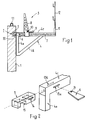
- FIG. 1 shows a wall 1 which has not yet been erected and which must be continued upwards (reinforcing wire 1.1). It has a recess 2 on the outside with a projection 20 for fastening a climbing bracket 3.
- the climbing bracket 3 comprises a flat frame 4 with triangular welded profile tubes 4a, 4b, 4c.
- the two profile tubes 4a, 4c are at right angles to one another and are braced through the profile tube 4b.
- the profiled tube 4a rests on the wall 1 when the climbing bracket is mounted, while the profiled tube 4c projects perpendicular to the wall 1.
- the latter can e.g. B. serve as a support for a catwalk formed by wooden boards.
- the profile tube 4c has a plug-in sleeve 11, into which a post 12 can be inserted to form a railing.
- a hook 5 is provided, which can be hung in the recess 2.
- the hook 5 is displaceable in the profile tube 4c in the direction of the tube axis stored.
- a cross wedge 6, which is displaceable perpendicular to the plane of the frame 4, serves to fix the hook 5 in the recess 2.
- the profile tube 4c has mutually opposite openings 13a, 13b through which the cross wedge 6 can be passed.
- the essentially cuboidal hook 5 has a slot 14 arranged parallel to its longitudinal axis at a suitable point. This is at the same height as the openings 13a, 13b, so that the cross wedge 6 can also be passed through the slot 14 brought into alignment with the openings 13a, 13b mentioned.
- the hook 5 has on its underside a recess 15 into which the projection 20 of the recess 2 projects. By moving the cross wedge 6, the hook 5, respectively. one side wall of the recess 15 pressed against the corresponding projection 20 of the recess 2.
- the relaxed hook position is shown in FIG. 3a and the tensioned hook position in FIG. 3b.
- the terms “front” / “rear” and “right” / “left” are used below on the basis of the orientation that leads to the end of the hook 5 protruding from the profiled tube 4c being at the front while the the spring 7 facing end is at the rear.
- the right side denotes the upper side in FIG. 3a / b and the left side in FIG. 3a / b the lower side of the figure.
- the wedge 6 is thus narrower on the right side in Fig. 3a, b than on the left side.
- Fig. 3b the cross wedge 6 is struck to the right.
- the hook 5 has been drawn into the profile tube 4c, the hook 5, respectively. its recess 15 is wedged in the recess 2, respectively. on the projection 20.
- the transverse wedge 6 is supported on the front narrow sides of the openings 13a, 13b.
- a bolt or pin 21 provided at the narrower end of the transverse wedge 6 creates a widening thereof, so that the transverse wedge cannot be pulled out of the slot-shaped opening 13b (for example in the relaxed position according to FIG. 3a).
- the captivity of the cross wedge 6 can be ensured in that the width of the cross wedge 6 is greater than the length of the slot-shaped opening 13a.
- a displaceable slide 8 is mounted on the profile tube 4c. It serves to hold the formwork in place.
- a displaceable locking wedge 9 arranged parallel to the profile tube 4c serves to fix the carriage 8 in a desired position. According to the invention it is secured with a cross wedge 10 or. jammed.
- FIG. 4 shows an axial longitudinal section of the profile tube 4c with the slide 8 attached
- FIG. 5 shows an axial cross section along the line AA (cf. FIG. 4).
- the carriage 8 has a sleeve 18 encompassing the profile tube 4c.
- the locking wedge 9 is pushed in a slot 19 between the outer wall of the carriage 8 and profile tube 4c.
- this slot 19 is not intended to interact directly with the locking wedge 9 for fixing the slide 8.
- a cross wedge 10 which is slidably mounted in two aligned lateral openings 17a, 17b and which ensures the actual fixing, is provided in the interior of the slide 8. If it is turned to the right (in the illustration according to FIG.
- the locking wedge 9 does not have to be knocked out with difficulty, but the cross wedge 10 (in the illustration according to FIG. 5) is knocked to the left, as a result of which the space between the underside of the cross wedge 10 and the top of the profile tube 4c is enlarged.
- the locking wedge 9 is released and can therefore be pulled out with ease.
- a nose 16 formed at the narrow end of the locking wedge 19 prevents the locking wedge from being pulled under the cross wedge 10.
- the locking wedge is thus captively movable between slide 8 and profile tube 4c.
- the transverse wedge 10 can also be held captively in the same way as the transverse wedge 6 with the aid of a pin.
- the cross wedge is typically a metal plate with a trapezoidal outline.
- a different spatial shape can also be selected as long as the wedge can perform the function according to the invention.
- the hook can also be mounted in the profile tube 4a instead of in the profile tube 4c and can be pivoted about an axis (perpendicular to the plane of the frame), wherein the pivoting of the hooks allows movement from a tensioned position to a relaxed position and vice versa.
- cross wedge according to the invention considerably simplifies and increases the safety when handling climbing brackets.
Abstract
Description
Die Erfindung bezieht sich auf eine an einer Wand einhängbare Kletterkonsole mit einem Rahmen und einem im Rahmen verschiebbar gelagerten, in einer Wandaussparung fixierbaren Haken.The invention relates to a climbing bracket which can be hung on a wall and has a frame and a hook which is mounted displaceably in the frame and can be fixed in a wall recess.
Beim Betonieren von hohen Wänden werden in der Regel Kletterkonsolen eingesetzt, die in speziell dafür vorgesehene Wandaussparungen einhängbar sind. Die Konsolen weisen typischerweise einen flachen dreieckigen Rahmen auf, dessen eine Seite bei installierter Konsole an der Wand anliegt und dessen zweite Seite zur Bildung eines Laufstegs senkrecht zur Wand absteht. Der Laufsteg wird z. B. durch auf benachbarte Konsolen aufgelegte Bretter gebildet. Ferner ist am äusseren Ende des Rahmens ein Pfosten für eine Absturzsicherung einsteckbar.When concreting high walls, climbing brackets are usually used, which can be hung in specially provided wall recesses. The brackets typically have a flat triangular frame, one side of which rests against the wall when the bracket is installed and the second side of which forms a walkway perpendicular to the wall Wall protrudes. The catwalk is z. B. formed by placed on adjacent consoles boards. Furthermore, a post for fall protection can be inserted at the outer end of the frame.
Aufgabe der Erfindung ist es nun, die bekannten Kletterkonsolen dahingehend weiterzubilden, dass sie einfach und gefahrlos montier- und demontierbar sind.The object of the invention is now to develop the known climbing brackets in such a way that they can be easily and safely assembled and disassembled.
Gemäss der Erfindung besteht die Lösung darin, dass bei einer Kletterkonsole der eingangs genannten Art der Haken mit einem parallel zur Wand verschiebbaren Querkeil in der Wandaussparung ver- bzw. entspannbar ist.According to the invention, the solution is that in the case of a climbing console of the type mentioned at the beginning, the hook can be relaxed or relaxed in the wall recess with a transverse wedge which can be moved parallel to the wall.
Da es für den Bauarbeiter in der Regel einfacher und weniger gefährlich ist, Hammerschläge zum Betätigen des Keils parallel und nicht senkrecht zur Wand auszuüben sind, haben die erfindungsgemässen Kletterkonsolen in der Praxis grosse Vorteile.Since it is generally easier and less dangerous for the construction worker to strike the hammer in parallel to actuate the wedge and not perpendicular to the wall, the climbing brackets according to the invention have great advantages in practice.
Der Rahmen und der in diesem bewegliche Haken können zu diesem Zweck miteinander fluchtende, in Bewegungsrichtung des Hakens verlaufende Schlitze aufweisen, in denen der Querkeil verschiebbar gelagert ist. Wird der Querkeil in die eine Richtung getrieben, dann wird der Haken leicht in den Rahmen hineingezogen und infolgedessen in der Wandaussparung fixiert. Wird der Querkeil in die andere Richtung zurückgetrieben, dann wird die Verriegelung gelöst.For this purpose, the frame and the hook movable in it can have slots which are aligned with one another and run in the direction of movement of the hook and in which the transverse wedge is slidably mounted. If the cross wedge is driven in one direction, the hook is pulled slightly into the frame and consequently fixed in the wall recess. If the cross wedge is driven back in the other direction, the lock is released.
Um das Lösen des Hakens zu vereinfachen, kann im Rahmen eine Feder untergebracht sein, die den Haken aus dem Rahmen hinaus in eine entspannte Lage drückt. Die Feder arbeitet also entgegengesetzt zum Keil.In order to simplify the release of the hook, a spring can be accommodated in the frame, which presses the hook out of the frame into a relaxed position. So the spring works in the opposite direction to the wedge.
Typischerweise ist der Rahmen in der Art eines verstrebten rechten Winkels ausgebildet, wobei an einem der rechtwinkligen Arme ein Schlitten verschiebbar gelagert ist. Dieser dient zum Festhalten einer Wandverschalung und ist in der jeweils gewünschten Position mit einem in Verschiebungsrichtung beweglichen Arretierungskeil fixierbar.The frame is typically designed in the manner of a braced right angle, a slide being slidably mounted on one of the right-angled arms. This is used to hold a wall formwork and can be fixed in the desired position with a locking wedge movable in the direction of displacement.
Gemäss einer besonders bevorzugten Ausführungsform der Erfindung ist der Arretierungskeil mit gegen einen am Schlitten vorgesehenen parallel zur Wand beweglichen Querkeil verklemmbar. Der Querkeil wirkt also auf eine Seite des Arretierungskeils und ist in geeignet ausgebildeten Schlitzen des Schlittens abgestützt.According to a particularly preferred embodiment of the invention, the locking wedge can be clamped against a cross wedge provided on the slide and movable parallel to the wall. The cross wedge thus acts on one side of the locking wedge and is supported in suitably designed slots in the slide.
Damit der Arretierungskeil unverlierbar zwischen Schlitten und Rahmen festgehalten wird, kann er in der Nähe seiner Keilspitze eine Nase aufweisen, welche genügend gross ist, um nicht unter dem Querkeil weggleiten zu können.So that the locking wedge is held captive between the slide and frame, it can have a nose near its wedge tip which is large enough not to be able to slide away under the cross wedge.
Die erfindungsgemässen Querkeile sind typischerweise durch flache, keilförmig geschnittene Plättchen verwirklicht, die mit Hilfe von aus der Plattenebene herausragenden Elementen (Zapfen, Schrauben, Bolzen etc.) unverlierbar gehalten sind.The cross wedges according to the invention are typically realized by flat, wedge-shaped cut plates which are held captively with the aid of elements (pins, screws, bolts, etc.) protruding from the plane of the plate.
Im übrigen kann die Kletterkonsole an sich bekannte vorteilhafte Merkmale wie Steckverbindungen für Sicherungspfosten, Vierkantrohrprofile usw. aufweisen.In addition, the climbing console can have advantageous features known per se, such as plug-in connections for securing posts, square tube profiles, etc.
Anhand eines Ausführungsbeispiels und im Zusammenhang mit den Figuren soll die Erfindung nun näher erläutert werden. Es zeigen:
- Fig. 1
- Eine erfindungsgemässe Kletterkonsole in der Seitenansicht;
- Fig. 2
- eine Explosionsdarstellung des durch Querkeil fixierbaren Hakens;
- Fig. 3a,b
- Schnittdarstellungen, bei denen sich der Haken einmal in entspannter und einmal in fixierter Stellung befindet;
- Fig. 4
- eine Schnittdarstellung des Mechanismus zum Arretieren des Schlittens;
- Fig. 5
- eine Schnittdarstellung gemäss Ansicht A-A aus Fig. 4.
- Fig. 1
- A climbing console according to the invention in side view;
- Fig. 2
- an exploded view of the hook fixable by cross wedge;
- 3a, b
- Sectional views, in which the hook is once in a relaxed and once in a fixed position;
- Fig. 4
- a sectional view of the mechanism for locking the carriage;
- Fig. 5
- 3 shows a sectional illustration according to view AA from FIG. 4.
In Fig. 1 ist eine noch nicht fertig errichtete Wand 1 gezeigt, die es nach oben fortzuführen gilt (Armierungsdraht 1.1). Sie weist auf der Aussenseite eine Aussparung 2 mit einem Vorsprung 20 zum Befestigen einer Kletterkonsole 3 auf.1 shows a wall 1 which has not yet been erected and which must be continued upwards (reinforcing wire 1.1). It has a
Die Kletterkonsole 3 umfasst einen ebenen Rahmen 4 mit dreieckförmig zusammengeschweissten Profilrohren 4a, 4b, 4c. Die beiden Profilrohre 4a, 4c stehen rechtwinklig zueinander und sind durch das Profilrohr 4b verstrebt. Wie aus Fig. 1 zu ersehen ist, liegt das Profilrohr 4a bei montierter Kletterkonsole an der Wand 1 auf, während das Profilrohr 4c senkrecht zur Wand 1 absteht. Letzteres kann z. B. als Träger für einen durch Holzbretter gebildeten Laufsteg dienen. Am äusseren Ende weist das Profilrohr 4c eine Steckhülse 11 auf, in welche ein Pfosten 12 zur Bildung eines Geländers eingesteckt werden kann.The
Zur Befestigung der Kletterkonsole 3 ist ein Haken 5 vorgesehen, welcher in der Aussparung 2 einhängbar ist. Der Haken 5 ist im Profilrohr 4c in Richtung der Rohrachse verschiebbar gelagert. Ein Querkeil 6, welcher senkrecht zur Ebene des Rahmens 4 verschiebbar ist, dient dazu, den Haken 5 in der Aussparung 2 zu fixieren.To attach the
Zur Erläuterung dieses Mechanismus wird auf die Fig. 2 und 3 Bezug genommen. Das Profilrohr 4c weist einander gegenüberliegende Oeffnungen 13a, 13b auf, durch die der Querkeil 6 hindurchführbar ist. Ebenso weist der im wesentlichen quaderförmige Haken 5 an geeigneter Stelle einen parallel zu seiner Längsachse angeordneten Schlitz 14 auf. Dieser ist auf gleicher Höhe wie die Oeffnungen 13a, 13b, so dass der Querkeil 6 durch den in fluchtender Stellung mit den genannten Oeffnungen 13a, 13b gebrachten Schlitz 14 ebenfalls hindurchführbar ist.To explain this mechanism, reference is made to FIGS. 2 and 3. The
Der Haken 5 weist auf seiner Unterseite eine Ausnehmung 15 auf, in welche der Vorsprung 20 der Aussparung 2 hineinragt. Durch Verschieben des Querkeils 6 wird der Haken 5 resp. die eine Seitenwand der Ausnehmung 15 gegen den entsprechenden Vorsprung 20 der Aussparung 2 gedrückt.The
In Fig. 3a ist die entspannte und in Fig. 3b die verspannte Hakenposition gezeigt.The relaxed hook position is shown in FIG. 3a and the tensioned hook position in FIG. 3b.
Zur Vereinfachung der Beschreibung werden im folgenden die Begriffe "vorne"/"hinten" und "rechts"/"links" unter Zugrundelegung derjenigen Orientierung verwendet, die dazu führt, dass das aus dem Profilrohr 4c herausragende Ende des Hakens 5 vorne ist, während das der Feder 7 zugewandte Ende hinten ist. Mit "rechts" wird die in Fig. 3a/b obere Seite und mit "links" die in Fig. 3a/b untere Seite der Figur bezeichnet. Der Keil 6 ist also in Fig. 3a,b auf der rechten Seite schmaler als auf der linken Seite.In order to simplify the description, the terms “front” / “rear” and “right” / “left” are used below on the basis of the orientation that leads to the end of the
In der Fig. 3a ist nun der Querkeil 6 nach links geschlagen. Die hintere Schmalseite des Schlitzes 14 liegt an der hinteren Längsseite des Querkeils 6 an. Der Haken 5 wird durch die Feder 7 in diese vordere Position gedrückt.In Fig. 3a, the
In Fig. 3b ist der Querkeil 6 nach rechts geschlagen. Der Haken 5 ist dadurch in das Profilrohr 4c hineingezogen worden, der Haken 5 resp. seine Ausnehmung 15 verkeilt sich in der Aussparung 2 resp. am Vorsprung 20. Der Querkeil 6 stützt sich an den vorderen Schmalseiten der Oeffnungen 13a, 13b ab.In Fig. 3b the
Ein am schmaleren Ende des Querkeils 6 vorgesehener Bolzen oder Zapfen 21 schafft eine Verbreiterung desselben, so dass der Querkeil nicht aus der schlitzförmigen Oeffnung 13b herausgezogen werden kann (z. B. in der entspannten Position gemäss Fig. 3a). In die andere Richtung kann die Unverlierbarkeit des Querkeils 6 dadurch gewährleistet werden, dass die Breite des Querkeils 6 grösser ist als die Länge der schlitzförmigen Oeffnung 13a.A bolt or pin 21 provided at the narrower end of the
Wie aus Fig. 1 weiter zu entnehmen ist, ist am Profilrohr 4c ein verschiebbarer Schlitten 8 gelagert. Er dient zum Festhalten der Verschalung. Ein parallel zum Profilrohr 4c angeordneter, verschiebbarer Arretierungskeil 9 dient dazu, den Schlitten 8 in einer gewünschten Position zu fixieren. Gemäss der Erfindung wird er mit einem Querkeil 10 gesichert resp. verklemmt.As can also be seen from FIG. 1, a
Fig. 4 zeigt einen Achsenlängsschnitt des Profilrohrs 4c mit aufgesetztem Schlitten 8 und Fig. 5 einen Achsenquerschnitt entlang der Linie A-A (vgl. Fig. 4). Der Schlitten 8 weist eine das Profilrohr 4c umgreifende Manschette 18 auf. In einen Schlitz 19 zwischen Aussenwand des Schlittens 8 und Profilrohr 4c ist der Arretierungskeil 9 geschoben. Dieser Schlitz 19 ist nun aber nicht dazu bestimmt, unmittelbar mit dem Arretierungskeil 9 zur Fixierung des Schlittens 8 zusammenzuwirken. Vielmehr ist im Inneren des Schlittens 8 ein in zwei fluchtend angeordneten seitlichen Oeffnungen 17a, 17b verschiebbar gelagerter Querkeil 10 vorgesehen, der die eigentliche Fixierung gewährleistet. Wird er (in der Darstellung gemäss Fig. 5) nach rechts geschlagen, dann verbleibt zwischen der Unterseite des Querkeils 10 und der dieser zugewandten Oberseite des Profilrohrs 4c ein geringerer Zwischenraum als wenn der Querkeil 10 vollständig nach links geschlagen ist. Zum Arretieren des Schlittens 8 wird somit der Querkeil 10 in diejenige Lage gebracht, die für den Arretierungskeil 9 relativ wenig Zwischenraum lässt. Sodann wird der Arretierungskeil 9 mit kräftigen Schlägen in den genannten Zwischenraum hineingetrieben, wodurch der Schlitten 8 auf dem Profilrohr 4c arretiert wird.FIG. 4 shows an axial longitudinal section of the
Es ist natürlich auch möglich, zunächst den Arretierungskeil 9 ganz unter den Schlitten 8 zu treiben und erst dann den Querkeil 10 bis zum Verklemmen mit dem Arretierungskeil 9 nach rechts zu schlagen.It is of course also possible to first drive the locking
Zum Lösen der Arretierung muss nun nicht etwa der Arretierungskeil 9 mühsam herausgeschlagen werden, sondern es wird der Querkeil 10 (in der Darstellung gemäss Fig. 5) nach links geschlagen, wodurch der Zwischenraum zwischen Unterseite des Querkeils 10 und Oberseite des Profilrohrs 4c vergrössert wird. Der Arretierungskeil 9 wird freigegeben und kann daher ohne Mühe herausgezogen werden.To release the locking, the locking
Eine am schmalen Ende des Arretierungskeils 19 ausgebildete Nase 16 verhindert, dass der Arretierungskeil unter dem Querkeil 10 hindurchgezogen werden kann. Der Arretierungskeil ist damit unverlierbar beweglich zwischen Schlitten 8 und Profilrohr 4c festgehalten. Auch der Querkeil 10 kann in gleicher Weise wie der Querkeil 6 mit Hilfe eines Zapfens unverlierbar festgehalten werden.A
Der Querkeil ist typischerweise eine Metallplatte mit trapezförmigem Umriss. Selbstverständlich kann aber auch eine andersartige Raumform gewählt werden, solange der Keil die erfindungsgemässe Funktion wahrnehmen kann.The cross wedge is typically a metal plate with a trapezoidal outline. Of course, a different spatial shape can also be selected as long as the wedge can perform the function according to the invention.
Auch in anderen Aspekten kann die oben beschriebene Ausführungsform abgewandelt werden. Im Prinzip kann der Haken statt im Profilrohr 4c auch im Profilrohr 4a und zwar um eine Achse (senkrecht zur Rahmenebene) schwenkbar gelagert sein, wobei durch das Schwenken der Haken von einer verspannten in eine entspannte Position und umgekehrt bewegt werden kann.The embodiment described above can also be modified in other aspects. In principle, the hook can also be mounted in the
Zusammenfassend kann festgehalten werden, dass der erfindungsgemässe Querkeil eine beträchtliche Vereinfachung und Erhöhung der Sicherheit bei der Handhabung von Kletterkonsolen mit sich bringt.In summary, it can be stated that the cross wedge according to the invention considerably simplifies and increases the safety when handling climbing brackets.
Claims (9)
Applications Claiming Priority (2)
| Application Number | Priority Date | Filing Date | Title |
|---|---|---|---|
| DE9301494U | 1993-02-04 | ||
| DE9301494U DE9301494U1 (en) | 1993-02-04 | 1993-02-04 |
Publications (2)
| Publication Number | Publication Date |
|---|---|
| EP0611257A1 true EP0611257A1 (en) | 1994-08-17 |
| EP0611257B1 EP0611257B1 (en) | 1997-04-16 |
Family
ID=6888933
Family Applications (1)
| Application Number | Title | Priority Date | Filing Date |
|---|---|---|---|
| EP94810060A Expired - Lifetime EP0611257B1 (en) | 1993-02-04 | 1994-02-04 | Climbing console |
Country Status (3)
| Country | Link |
|---|---|
| EP (1) | EP0611257B1 (en) |
| AT (1) | ATE151841T1 (en) |
| DE (2) | DE9301494U1 (en) |
Cited By (7)
| Publication number | Priority date | Publication date | Assignee | Title |
|---|---|---|---|---|
| DE29500048U1 (en) * | 1995-01-03 | 1995-04-06 | Effkemann Manfred | Scaffolding suspension |
| WO1997029259A1 (en) * | 1996-02-09 | 1997-08-14 | Ebersjoe Hans | An entrance device |
| DE19700952A1 (en) * | 1996-07-20 | 1998-01-29 | Tulke Elvira | Device for anchoring scaffolds, especially against walls of houses |
| US20100025151A1 (en) * | 2004-12-01 | 2010-02-04 | Jose Ramon Guinart Pallares | Integral safety system which can be used for construction |
| EP3032002A1 (en) | 2014-12-12 | 2016-06-15 | Mägert & Co. Innovation | Climbing console and lagging member for such |
| EP3150780A1 (en) * | 2015-09-29 | 2017-04-05 | Safety Solutions Jonsereds AB | A temporary edge protection system |
| EP3543428A3 (en) * | 2018-03-20 | 2019-11-13 | Pino Albanese | Method for connecting a climbing bracket which is activatable automatically safe with an anchoring device, system for attaching a climbing bracket, climbing bracket around an anchoring device and a formwork plate holder |
Families Citing this family (5)
| Publication number | Priority date | Publication date | Assignee | Title |
|---|---|---|---|---|
| DE102004020345B4 (en) * | 2004-04-27 | 2010-04-22 | Bügel, Klaus | Support system for a Konsolgerüst and Konsolgerüst having the carrier system |
| ES2293757B1 (en) * | 2004-07-01 | 2009-03-16 | Jose Antonio Alba Irurzun | IMPROVED MENSULA AND REGISTRATION SYSTEM. |
| DE102007012197A1 (en) * | 2007-03-14 | 2008-09-18 | Kentzler-Kaschner Dental Gmbh | Sensor holder for dental radiography, has carriage fixable in different positions relative to guiding part by holding device, and holding device comprising clamping part, by which carriage is continuously locakable relative to guiding part |
| EP3006647A4 (en) * | 2013-05-28 | 2016-11-16 | Total Kankyo Co Ltd | High-rise building and maintenance method therefor |
| FR3100554B1 (en) * | 2019-09-08 | 2021-08-20 | Sateco Sa | Folding cantilever work structure comprising an interface member configured to fill a horizontal gap |
Citations (10)
| Publication number | Priority date | Publication date | Assignee | Title |
|---|---|---|---|---|
| FR1190417A (en) * | 1958-01-24 | 1959-10-12 | protective scaffolding | |
| US3070337A (en) * | 1959-12-01 | 1962-12-25 | Gates & Sons | Scaffold support bracket |
| GB985913A (en) * | 1960-06-14 | 1965-03-10 | Kwikform Ltd | Improvements in or relating to builders scaffolding |
| DE1222230B (en) * | 1958-05-29 | 1966-08-04 | Karl Heilwagen & Co | Reusable cantilever scaffolding anchored to a structure |
| FR2054794A5 (en) * | 1969-07-30 | 1971-05-07 | Provence Metal Const | |
| FR2277209A1 (en) * | 1974-07-05 | 1976-01-30 | Batimetal Sa | Sectional shuttering with locking pins - has pins through tapered bore sleeves welded to panel reinforcement |
| DE3429630A1 (en) * | 1984-08-11 | 1986-02-20 | Peri-Werk Artur Schwörer GmbH & Co KG, 7912 Weißenhorn | Transverse strut for stacking tower |
| DE3903575A1 (en) * | 1989-02-07 | 1990-08-09 | Wolfgang Baumann | Retaining apparatus which is to be used in the building industry and is intended for retaining auxiliary devices, in particular guardrail boards or shuttering boards |
| US4964747A (en) * | 1990-01-09 | 1990-10-23 | Vinson Michael A | Concrete form bracket |
| DE4115597A1 (en) * | 1991-05-14 | 1992-11-19 | Baumann Verwertungs Gmbh | Formwork support for construction of extensions to existing building - includes support designed for easy removal from cast external corners |
-
1993
- 1993-02-04 DE DE9301494U patent/DE9301494U1/de not_active Expired - Lifetime
-
1994
- 1994-02-04 EP EP94810060A patent/EP0611257B1/en not_active Expired - Lifetime
- 1994-02-04 AT AT94810060T patent/ATE151841T1/en not_active IP Right Cessation
- 1994-02-04 DE DE59402408T patent/DE59402408D1/en not_active Expired - Fee Related
Patent Citations (10)
| Publication number | Priority date | Publication date | Assignee | Title |
|---|---|---|---|---|
| FR1190417A (en) * | 1958-01-24 | 1959-10-12 | protective scaffolding | |
| DE1222230B (en) * | 1958-05-29 | 1966-08-04 | Karl Heilwagen & Co | Reusable cantilever scaffolding anchored to a structure |
| US3070337A (en) * | 1959-12-01 | 1962-12-25 | Gates & Sons | Scaffold support bracket |
| GB985913A (en) * | 1960-06-14 | 1965-03-10 | Kwikform Ltd | Improvements in or relating to builders scaffolding |
| FR2054794A5 (en) * | 1969-07-30 | 1971-05-07 | Provence Metal Const | |
| FR2277209A1 (en) * | 1974-07-05 | 1976-01-30 | Batimetal Sa | Sectional shuttering with locking pins - has pins through tapered bore sleeves welded to panel reinforcement |
| DE3429630A1 (en) * | 1984-08-11 | 1986-02-20 | Peri-Werk Artur Schwörer GmbH & Co KG, 7912 Weißenhorn | Transverse strut for stacking tower |
| DE3903575A1 (en) * | 1989-02-07 | 1990-08-09 | Wolfgang Baumann | Retaining apparatus which is to be used in the building industry and is intended for retaining auxiliary devices, in particular guardrail boards or shuttering boards |
| US4964747A (en) * | 1990-01-09 | 1990-10-23 | Vinson Michael A | Concrete form bracket |
| DE4115597A1 (en) * | 1991-05-14 | 1992-11-19 | Baumann Verwertungs Gmbh | Formwork support for construction of extensions to existing building - includes support designed for easy removal from cast external corners |
Cited By (10)
| Publication number | Priority date | Publication date | Assignee | Title |
|---|---|---|---|---|
| DE29500048U1 (en) * | 1995-01-03 | 1995-04-06 | Effkemann Manfred | Scaffolding suspension |
| WO1997029259A1 (en) * | 1996-02-09 | 1997-08-14 | Ebersjoe Hans | An entrance device |
| DE19700952A1 (en) * | 1996-07-20 | 1998-01-29 | Tulke Elvira | Device for anchoring scaffolds, especially against walls of houses |
| DE19700952C2 (en) * | 1996-07-20 | 1999-11-04 | Tulke Elvira | Device for anchoring scaffolding |
| US20100025151A1 (en) * | 2004-12-01 | 2010-02-04 | Jose Ramon Guinart Pallares | Integral safety system which can be used for construction |
| US8245816B2 (en) * | 2004-12-01 | 2012-08-21 | Jose Ramon Guinart Pallares | Integral safety system which can be used for construction |
| EP3032002A1 (en) | 2014-12-12 | 2016-06-15 | Mägert & Co. Innovation | Climbing console and lagging member for such |
| EP3032002B1 (en) | 2014-12-12 | 2021-03-24 | Mägert & Co. Innovation | Climbing console and lagging member for such |
| EP3150780A1 (en) * | 2015-09-29 | 2017-04-05 | Safety Solutions Jonsereds AB | A temporary edge protection system |
| EP3543428A3 (en) * | 2018-03-20 | 2019-11-13 | Pino Albanese | Method for connecting a climbing bracket which is activatable automatically safe with an anchoring device, system for attaching a climbing bracket, climbing bracket around an anchoring device and a formwork plate holder |
Also Published As
| Publication number | Publication date |
|---|---|
| ATE151841T1 (en) | 1997-05-15 |
| DE59402408D1 (en) | 1997-05-22 |
| DE9301494U1 (en) | 1993-04-15 |
| EP0611257B1 (en) | 1997-04-16 |
Similar Documents
| Publication | Publication Date | Title |
|---|---|---|
| DE2704398B2 (en) | Framework that can be assembled from uprights and bars | |
| DE60022490T2 (en) | FRAME ELEMENTS WITH CLOSURE ELEMENT | |
| EP0611257B1 (en) | Climbing console | |
| DE3147081A1 (en) | Supporting framework for concrete shutterings | |
| DE3627583C2 (en) | ||
| EP3440281B1 (en) | Metal fitting for a toe board of a scaffold | |
| EP0369153B1 (en) | Device for connecting additional elements to forming panels | |
| DE4007950A1 (en) | Shuttering panel clamping connector - has fixed and adjustable claws on traverse, engaging panel frame recesses | |
| DE3108020A1 (en) | "PROTECTIVE DEVICE FOR METAL FRAME" | |
| DE102019204713A1 (en) | Formwork system for the production of concrete walls | |
| DE2156392A1 (en) | Component for masts subject to bending loads, especially for elevator, crane and antenna masts | |
| EP3748107B1 (en) | Mounting adapter, safety rail, kit for a scaffold, scaffold and method therefor | |
| DE3401906A1 (en) | Apparatus for the suspended fastening of a scaffold element | |
| DE2648543A1 (en) | Collapsible scaffolding structure with stiff connectors - has tubular members with pins for holding transverse platform members | |
| EP0331796B1 (en) | Reinforced suspension member for cables | |
| DE102016111211A1 (en) | Formwork system for the construction of low construction sections of in-situ concrete | |
| DE3222811C1 (en) | Connection device for dismantled half-timbered buildings | |
| CH705280B1 (en) | Abschalplattenträger for a console. | |
| EP1362150B1 (en) | Scaffolding frame for a system scaffold | |
| DE202023105830U1 (en) | Device for attaching fall protection to scaffolding | |
| DE202023106733U1 (en) | Device for attaching fall protection to scaffolding | |
| DE10112369B4 (en) | Scaffolding frames for a system scaffolding | |
| DE8004954U1 (en) | ANGLE BRACKET FOR DETERMINING CONTROL PANELS ABOVE CORNER | |
| AT328168B (en) | TENSIONING ELEMENT FOR FASTENING, CONNECTING AND / OR ALIGNING FORMWORK PARTS | |
| EP0392628B1 (en) | Shuttering for pouring walls and vertical support for such shuttering |
Legal Events
| Date | Code | Title | Description |
|---|---|---|---|
| PUAI | Public reference made under article 153(3) epc to a published international application that has entered the european phase |
Free format text: ORIGINAL CODE: 0009012 |
|
| AK | Designated contracting states |
Kind code of ref document: A1 Designated state(s): AT CH DE FR LI |
|
| 17P | Request for examination filed |
Effective date: 19950120 |
|
| 17Q | First examination report despatched |
Effective date: 19950927 |
|
| GRAG | Despatch of communication of intention to grant |
Free format text: ORIGINAL CODE: EPIDOS AGRA |
|
| GRAH | Despatch of communication of intention to grant a patent |
Free format text: ORIGINAL CODE: EPIDOS IGRA |
|
| GRAH | Despatch of communication of intention to grant a patent |
Free format text: ORIGINAL CODE: EPIDOS IGRA |
|
| GRAA | (expected) grant |
Free format text: ORIGINAL CODE: 0009210 |
|
| AK | Designated contracting states |
Kind code of ref document: B1 Designated state(s): AT CH DE FR LI |
|
| PG25 | Lapsed in a contracting state [announced via postgrant information from national office to epo] |
Ref country code: FR Effective date: 19970416 |
|
| REF | Corresponds to: |
Ref document number: 151841 Country of ref document: AT Date of ref document: 19970515 Kind code of ref document: T |
|
| REG | Reference to a national code |
Ref country code: CH Ref legal event code: EP |
|
| REF | Corresponds to: |
Ref document number: 59402408 Country of ref document: DE Date of ref document: 19970522 |
|
| EN | Fr: translation not filed | ||
| PG25 | Lapsed in a contracting state [announced via postgrant information from national office to epo] |
Ref country code: AT Free format text: LAPSE BECAUSE OF NON-PAYMENT OF DUE FEES Effective date: 19980204 |
|
| PLBE | No opposition filed within time limit |
Free format text: ORIGINAL CODE: 0009261 |
|
| STAA | Information on the status of an ep patent application or granted ep patent |
Free format text: STATUS: NO OPPOSITION FILED WITHIN TIME LIMIT |
|
| 26N | No opposition filed | ||
| PGFP | Annual fee paid to national office [announced via postgrant information from national office to epo] |
Ref country code: DE Payment date: 20040308 Year of fee payment: 11 |
|
| PG25 | Lapsed in a contracting state [announced via postgrant information from national office to epo] |
Ref country code: DE Free format text: LAPSE BECAUSE OF NON-PAYMENT OF DUE FEES Effective date: 20050901 |
|
| REG | Reference to a national code |
Ref country code: CH Ref legal event code: PFA Owner name: MAEGERT BAUTECHNIK AG Free format text: MAEGERT BAUTECHNIK AG#PARALLELSTRASSE 60#CH-3714 FRUTIGEN (CH) -TRANSFER TO- MAEGERT BAUTECHNIK AG#ZWYDENWEG 16#6052 HERGISWIL (CH) |
|
| PGFP | Annual fee paid to national office [announced via postgrant information from national office to epo] |
Ref country code: CH Payment date: 20130312 Year of fee payment: 20 |
|
| REG | Reference to a national code |
Ref country code: CH Ref legal event code: PL |