EP0610483B1 - Device for enriching water with co 2? gas in order to generate carbonated water and use of the device - Google Patents
Device for enriching water with co 2? gas in order to generate carbonated water and use of the device Download PDFInfo
- Publication number
- EP0610483B1 EP0610483B1 EP93919164A EP93919164A EP0610483B1 EP 0610483 B1 EP0610483 B1 EP 0610483B1 EP 93919164 A EP93919164 A EP 93919164A EP 93919164 A EP93919164 A EP 93919164A EP 0610483 B1 EP0610483 B1 EP 0610483B1
- Authority
- EP
- European Patent Office
- Prior art keywords
- water
- circulating pump
- ice
- gas
- storage container
- Prior art date
- Legal status (The legal status is an assumption and is not a legal conclusion. Google has not performed a legal analysis and makes no representation as to the accuracy of the status listed.)
- Expired - Lifetime
Links
Images
Classifications
-
- B—PERFORMING OPERATIONS; TRANSPORTING
- B01—PHYSICAL OR CHEMICAL PROCESSES OR APPARATUS IN GENERAL
- B01F—MIXING, e.g. DISSOLVING, EMULSIFYING OR DISPERSING
- B01F23/00—Mixing according to the phases to be mixed, e.g. dispersing or emulsifying
- B01F23/20—Mixing gases with liquids
- B01F23/23—Mixing gases with liquids by introducing gases into liquid media, e.g. for producing aerated liquids
- B01F23/236—Mixing gases with liquids by introducing gases into liquid media, e.g. for producing aerated liquids specially adapted for aerating or carbonating beverages
- B01F23/2362—Mixing gases with liquids by introducing gases into liquid media, e.g. for producing aerated liquids specially adapted for aerating or carbonating beverages for aerating or carbonating within receptacles or tanks, e.g. distribution machines
-
- B—PERFORMING OPERATIONS; TRANSPORTING
- B67—OPENING, CLOSING OR CLEANING BOTTLES, JARS OR SIMILAR CONTAINERS; LIQUID HANDLING
- B67D—DISPENSING, DELIVERING OR TRANSFERRING LIQUIDS, NOT OTHERWISE PROVIDED FOR
- B67D1/00—Apparatus or devices for dispensing beverages on draught
- B67D1/0042—Details of specific parts of the dispensers
- B67D1/0057—Carbonators
-
- B—PERFORMING OPERATIONS; TRANSPORTING
- B01—PHYSICAL OR CHEMICAL PROCESSES OR APPARATUS IN GENERAL
- B01F—MIXING, e.g. DISSOLVING, EMULSIFYING OR DISPERSING
- B01F35/00—Accessories for mixers; Auxiliary operations or auxiliary devices; Parts or details of general application
- B01F35/20—Measuring; Control or regulation
- B01F35/21—Measuring
- B01F35/212—Measuring of the driving system data, e.g. torque, speed or power data
-
- B—PERFORMING OPERATIONS; TRANSPORTING
- B67—OPENING, CLOSING OR CLEANING BOTTLES, JARS OR SIMILAR CONTAINERS; LIQUID HANDLING
- B67D—DISPENSING, DELIVERING OR TRANSFERRING LIQUIDS, NOT OTHERWISE PROVIDED FOR
- B67D1/00—Apparatus or devices for dispensing beverages on draught
- B67D1/08—Details
- B67D1/0857—Cooling arrangements
- B67D1/0858—Cooling arrangements using compression systems
- B67D1/0861—Cooling arrangements using compression systems the evaporator acting through an intermediate heat transfer means
-
- B—PERFORMING OPERATIONS; TRANSPORTING
- B01—PHYSICAL OR CHEMICAL PROCESSES OR APPARATUS IN GENERAL
- B01F—MIXING, e.g. DISSOLVING, EMULSIFYING OR DISPERSING
- B01F35/00—Accessories for mixers; Auxiliary operations or auxiliary devices; Parts or details of general application
- B01F35/90—Heating or cooling systems
- B01F2035/98—Cooling
-
- Y—GENERAL TAGGING OF NEW TECHNOLOGICAL DEVELOPMENTS; GENERAL TAGGING OF CROSS-SECTIONAL TECHNOLOGIES SPANNING OVER SEVERAL SECTIONS OF THE IPC; TECHNICAL SUBJECTS COVERED BY FORMER USPC CROSS-REFERENCE ART COLLECTIONS [XRACs] AND DIGESTS
- Y10—TECHNICAL SUBJECTS COVERED BY FORMER USPC
- Y10S—TECHNICAL SUBJECTS COVERED BY FORMER USPC CROSS-REFERENCE ART COLLECTIONS [XRACs] AND DIGESTS
- Y10S261/00—Gas and liquid contact apparatus
- Y10S261/07—Carbonators
Definitions
- the present invention relates to a device and the use of a device for enriching water with CO2 gas for the production of carbonated water in a storage container, which is provided for cooling its contents and for forming an ice jacket in the wall area with cooling lines of a cooling circuit in the inside of which a circulation pump is arranged, through which CO2 gas from the head region of the storage container is mixed into the water and / or the water inside the storage container is rotated and / or circulated, and in which both water and CO2 gas in the head region can be supplied and removed from the carbonated water in the bottom area.
- Such devices for enriching water with CO2 gas for the production of carbonated water are used, for example, in devices through which CO2-containing soft drinks can be prepared and mixed by mixing carbonated water with an appropriate beverage concentrate.
- the beverage concentrate Soda water to be mixed is created in the storage container by enriching water with CO2 gas supplied and cooled for better carbonation and as a prerequisite for a prepared cool soft drink.
- Normal water of drinking quality is fed to this reservoir, the so-called carbonator, either from the line of a water supply system or from a reservoir under sufficient pressure, whereby the water supplied can itself be under pressure or can be pumped into the carbonator exclusively or additionally by a pressure pump.
- the carbonator is supplied with CO2 gas, namely from a CO2 gas reservoir via a pressure reducing valve, so that a pressure of, for example, approximately 4 bar is built up in the carbonator.
- CO2 gas namely from a CO2 gas reservoir via a pressure reducing valve
- the carbonation of the water in the carbonator with the supplied CO2 gas is carried out or supported by various measures, the use of circulation pumps arranged in the carbonator having proven successful. These suck this CO2 gas from the head area of the carbonator filled with CO2 gas and introduce it into the water which is set in motion, in particular in rotation.
- cooling the carbonator serves on the one hand to improve the carbonation and on the other hand as a prerequisite that the final prepared and dispensed beverage has the desired low and essentially constant temperature.
- the carbonator is expediently cooled by means of a cooling system which is able to build up an ice jacket in the side region of the side walls of the carbonator, which is formed to a certain extent by the circulated water.
- a cooling system which is able to build up an ice jacket in the side region of the side walls of the carbonator, which is formed to a certain extent by the circulated water.
- a shut-off valve is opened in a line adjoining the bottom area of the carbonator and the cooled, carbonated water is removed for this purpose. Since the water is cooled in the vicinity of the freezing point in the area of the cooling coils with regard to the ice jacket which is being formed, there is a certain risk that ice particles or parts will get into the area of the outflow opening and block it. Ice formation in this area itself is rather impossible, because due to the special behavior of the water with regard to its specific density in the vicinity of the freezing point, the somewhat warmer water would sink downwards, and since the outlet opening is expediently arranged in the vicinity of the circulation pump, which radiates some heat is.
- a device which meets these requirements is characterized in that a time control circuit is provided and the circulation pump within the Storage container, which is used to produce carbonated water by enriching water with CO2 gas, controlled by the time control circuit, is put into operation and taken out of operation in continuous cycles.
- a device with measures according to these features of the invention is characterized in that the sufficient carbonation of the water with CO2 gas is accomplished and / or supported in the operating phases of the circulation pump and the ice jacket is formed essentially in a ring shape on the cooled wall of the storage container.
- the carbonized water can layer up according to its natural density, whereby the slightly warmer water sinks down and the somewhat colder water rises together with any ice particles or ice particles that may be present, whereby the ice particles and ice particles tend to come together and lie on the ice jacket in the upper area of the carbonator.
- the circulation pump can be clocked by a timing control circuit that functions simply in terms of control technology.
- the device according to the invention is preferably operated in such a way that the on-time of the circulating pump is approximately 1 to 2 minutes and the ratio of the on-time to the off-time is approximately 1:10 to 1:20. It turns out that a switch-on time of one to two minutes within switch-on-switch-off cycles from 1:10 to 1:20 is sufficient re-carbonation of the water and is able to achieve a sufficiently uniform ice jacket design.
- the use of the device according to the invention is characterized in that when carbonated water is removed from the storage container or when fresh water is supplied to the storage container, the circulation pump is put into operation during this phase including a follow-up phase. A follow-up phase of approx. 2 to 4 minutes is advisable. Then the control cycle starts again, in which the circulation pump is switched on for 1 to 2 minutes and the switch-off time between the switch-on phases is 10 to 20 times as long.
- a storage container 1 is suitable and intended for use in devices for the preparation of soft drinks by admixing an appropriate concentrate to carbonated water or possibly also to normal water.
- Fresh water is supplied to the reservoir via a supply line 2 and CO2 gas is supplied via a supply line 3.
- Sufficiently carbonated and chilled water is removed in portions via an outlet line 4 in order to prepare a soft drink.
- the sufficient carbonation is at least supported by a circulation pump 5, which sucks the CO2 gas located there from the head region 6 of the storage container 1 via an intake pipe 7 and mixes it into the stored water 8 at the level of the circulation pump 5. This CO2 gas is largely dissolved in the water 8.
- the circulation pump 5 is driven by an electric motor 9.
- the cooling of the water supply takes place via evaporator coils 10 of a cooling system, not shown, in such a way that an ice jacket 11 builds up in the interior of the storage container 1 in the region of the evaporator coils 10, which rest on the wall of the storage container 1 with good thermal conductivity.
- the thickness of this ice jacket 11 is monitored by an ice sensor 12, from which the refrigeration cycle and thus the cooling capacity is controlled.
- this ice jacket 11 has the effect that, without very sensitive detection and evaluation measures, the supply of water 8 is cooled to a very constant temperature in the immediate vicinity of the freezing point, and the temperature is also essentially maintained when water changes take place, ie when carbonized Water is removed via the outlet line 4 and - controlled by a water level sensor 13 - warmer water is supplied via the feed line 2 for this purpose.
- the ice jacket degrades relatively quickly around sub-areas, which then be built up again by cooling power supplied via the evaporator lines 10.
- a known measure is to prevent icing of the outlet opening by arranging it in the vicinity and / or below the circulating pump, the heating, in particular of the drive motor 9, having a positive effect against icing.
- this measure cannot be sufficient against floating ice particles.
- the electric motor 9 is driven intermittently.
- An operating phase of approx. 1 to 2 minutes is followed by a rest phase of approx. 10 to 20 times the length.
- the circulated water 8 calms down and ice particles and ice particles floating in this water, because of their lower density, endeavor to reach the area of the surface of the water in order to unite there and / or in the edge areas to put on the ice jacket 10.
- these hazard elements are thus neutralized.
- the electric motor 9 is actuated each time carbonized water is added or fresh water is added, and the circulation pump 5 is put into operation for these time periods including a follow-up time, after which the switch-on-switch-off cycle starts again as originally.
- the circuitry measures are arbitrarily simple and can be implemented, for example, in that a signal is derived from the water level sensor 13, which sets a counting chain into an initial situation during a water inflow, which causes the power supply switch 15 to the electric motor 9 to be closed. If the water level sensor 13 detects that enough water has been refilled, the water supply via the feed line 2 is blocked and the counting chain 14 begins to run off. For a time range of 1 to 2 minutes, depending on the design of the counting chain, the switch 15 remains closed, after which it is opened until the counting chain has reached the upper setting value, after which it can be switched back to the initial situation and run through again.
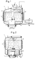
- FIG. 2 shows a modification of a storage container according to FIG. 1, wherein the storage container 1 'only has evaporator coils 10' applied to it in the upper wall area is so that the ice sheet is also preferably formed in the upper region of the storage container 1 '.
- the circulation pump 5 'and its drive motor 9' run coils 16 through which other water to be cooled is passed through the carbonized water. Due to the resting phases of the circulation pump, the somewhat warmer water 8 'collects in the lower zones of the storage container 1' because of its greater density, so that a risk of icing in the coils 16 is also prevented.
Abstract
Description
Die vorliegende Erfindung bezieht sich auf eine Vorrichtung und die Verwendung einer Vorrichtung zum Anreichern von Wasser mit CO₂-Gas zur Erzeugung von karbonisiertem Wasser in einem Vorratsbehälter, welcher zur Kühlung seines Inhalts und zur Bildung eines Eismantels im Wandungsbereich mit Kühlleitungen eines Kühlkreislaufs versehen ist, in dessen Inneren eine Umwälzpumpe angeordnet ist, durch welche CO₂-Gas aus dem Kopfbereich des Vorratsbehälters in das Wasser eingemischt und/oder das Wasser innerhalb des Vorratsbehälters in Rotation und/oder Zirkulation versetzt wird, und in den sowohl Wasser als auch CO₂-Gas im Kopfbereich zuführbar und aus dem karbonisiertes Wasser im Bodenbereich entnehmbar ist.The present invention relates to a device and the use of a device for enriching water with CO₂ gas for the production of carbonated water in a storage container, which is provided for cooling its contents and for forming an ice jacket in the wall area with cooling lines of a cooling circuit in the inside of which a circulation pump is arranged, through which CO₂ gas from the head region of the storage container is mixed into the water and / or the water inside the storage container is rotated and / or circulated, and in which both water and CO₂ gas in the head region can be supplied and removed from the carbonated water in the bottom area.
Derartige Vorrichtungen zum Anreichern von Wasser mit CO₂-Gas zur Erzeugung von karbonisiertem Wasser werden beispielsweise in Geräten zum Einsatz gebracht, durch welche CO₂-haltige Erfrischungsgetränke durch Mischung von karbonisiertem Wasser mit einem entsprechenden Getränkekonzentrat bereitet und ausgegeben werden können. Das dem Getränkekonzentrat zuzumischende Sodawasser wird dabei in dem Vorratsbehälter durch Anreicherung von Wasser mit zugeführtem CO₂-Gas erstellt und zur besseren Karbonisierung sowie als Voraussetzung für ein bereitetes kühles Erfrischungsgetränk gekühlt. Diesem Vorratsbehälter, dem sogenannten Karbonisator, wird normales Wasser in Trinkqualität entweder aus der Leitung eines Wasserversorgungssystems oder einem Vorratsbehälter unter ausreichendem Druck zugeführt, wobei das Zugeführte Wasser selbst unter Druck stehen kann oder aber durch eine Druckpumpe ausschließlich oder zusätzlich in den Karbonisator gefördert wird. Außerdem wird dem Karbonisator CO₂-Gas zugeführt, und zwar aus einem CO₂-Gas-Vorratsbehälter über ein Druckminder-Regelventil, so daß im Karbonisator ein Druck von beispielsweise ca. 4 Bar aufgebaut ist. Durch verschiedene Maßnahmen wird die Karbonisierung des Wassers im Karbonisator mit dem zugeführten CO₂-Gas durchgeführt bzw. unterstützt, wobei sich der Einsatz von im Karbonisator angeordneten Umwälzpumpen bewährt hat. Diese saugen aus dem mit CO₂-Gas gefüllten Kopfbereich des Karbonisators dieses CO₂-Gas an und führen dieses in das in Bewegung, insbesondere in Drehung versetzte Wasser ein. Wie bereits ausgeführt, dient eine Kühlung des Karbonisators zum einen der Verbesserung der Karbonisierung und zum anderen als Voraussetzung, daß das endgültig bereitete und ausgegebene Getränk die gewünschte niedrige und im wesentlichen konstante Temperatur aufweist. Die Kühlung des Karbonisators erfolgt zweckmäßig über ein Kühlsystem, das in der Lage ist, im Seitenbereich der Seitenwandungen des Karbonisators einen Eismantel aufzubauen, welcher sich durch das umgewälzte Wasser einigermaßen gleich stark ausbildet. Dadurch wird "Kältekapazität" gespeichert und das Kühlsystem braucht nicht extrem leistungsstark ausgelegt werden, wie dies bei Durchflußkühlung notwendig wäre. Anordnungen mit einem entsprechenden Aufbau sind bekannt (DE-A-40 25 986.2).Such devices for enriching water with CO₂ gas for the production of carbonated water are used, for example, in devices through which CO₂-containing soft drinks can be prepared and mixed by mixing carbonated water with an appropriate beverage concentrate. The beverage concentrate Soda water to be mixed is created in the storage container by enriching water with CO₂ gas supplied and cooled for better carbonation and as a prerequisite for a prepared cool soft drink. Normal water of drinking quality is fed to this reservoir, the so-called carbonator, either from the line of a water supply system or from a reservoir under sufficient pressure, whereby the water supplied can itself be under pressure or can be pumped into the carbonator exclusively or additionally by a pressure pump. In addition, the carbonator is supplied with CO₂ gas, namely from a CO₂ gas reservoir via a pressure reducing valve, so that a pressure of, for example, approximately 4 bar is built up in the carbonator. The carbonation of the water in the carbonator with the supplied CO₂ gas is carried out or supported by various measures, the use of circulation pumps arranged in the carbonator having proven successful. These suck this CO₂ gas from the head area of the carbonator filled with CO₂ gas and introduce it into the water which is set in motion, in particular in rotation. As already stated, cooling the carbonator serves on the one hand to improve the carbonation and on the other hand as a prerequisite that the final prepared and dispensed beverage has the desired low and essentially constant temperature. The carbonator is expediently cooled by means of a cooling system which is able to build up an ice jacket in the side region of the side walls of the carbonator, which is formed to a certain extent by the circulated water. As a result, "cooling capacity" is stored and the cooling system need not be designed to be extremely powerful, as is necessary with flow cooling would. Arrangements with a corresponding structure are known (DE-A-40 25 986.2).
Wird beispielsweise im beschriebenen Anwendungsfall die Ausgabe eines frisch bereiteten Erfrischungsgetränks gewünscht, so wird in einer an den Bodenbereich des Karbonisators anschließenden Leitung ein Absperrventil geöffnet und das gekühlte, karbonisierte Wasser zu diesem Zweck entnommen. Da das Wasser von im Hinblick auf den sich ausbildenden Eismantel im Bereich der Kühlschlangen in die Nähe des Gefrierpunktes gekühlt ist, besteht eine gewisse Gefahr, daß Eisteilchen oder -teile in den Bereich der Ausflußöffnung gelangen und diese verstopfen. Eine Eisbildung in diesem Bereich selbst ist eher ausgeschlossen, da wegen des besonderen Verhaltens des Wassers bezüglich seiner spezifischen Dichte in der Nähe des Gefrierpunktes das etwas wärmere Wasser nach unten absinken würde, und da die Auslauföffnung zweckmäßigerweise im Nahbereich der an sich etwas Wärme ausstrahlenden Umwälzpumpe angeordnet ist. Durch die Umwälzbewegung des Wassers, die zum Karbonisieren und zum gleichmäßigen Ausbilden des Eismantels an den Wandungen notwendig oder zumindest zweckdieniich ist, kann jedoch sich ablösendes Eis oder aber in den oberen Bereichen schwimmendes oder schwebendes Eis bei insbesondere geöffnetem Ausgabekanal in dessen Bereich gelangen.If, for example, in the described application, the delivery of a freshly prepared soft drink is desired, a shut-off valve is opened in a line adjoining the bottom area of the carbonator and the cooled, carbonated water is removed for this purpose. Since the water is cooled in the vicinity of the freezing point in the area of the cooling coils with regard to the ice jacket which is being formed, there is a certain risk that ice particles or parts will get into the area of the outflow opening and block it. Ice formation in this area itself is rather impossible, because due to the special behavior of the water with regard to its specific density in the vicinity of the freezing point, the somewhat warmer water would sink downwards, and since the outlet opening is expediently arranged in the vicinity of the circulation pump, which radiates some heat is. Due to the circulating movement of the water, which is necessary or at least expedient for the carbonization and for the uniform formation of the ice jacket on the walls, however, detaching ice or floating or floating ice in the upper areas can reach its area with the delivery channel in particular open.
Es ist nunmehr Aufgabe der vorliegenden Erfindung, eine Vorrichtung für diesen Anwendungsbereich zu schaffen, welche ein störungsfreies Arbeiten des Karbonisators sicherstellt.It is an object of the present invention to provide a device for this area of application which ensures trouble-free operation of the carbonator.
Eine Vorrichtung, die diesen Anforderungen gerecht wird, ist dadurch gekennzeichnet, daß eine Zeitsteuerschaltung vorgesehen ist und die Umwälzpumpe innerhalb des Vorratsbehälters, der zur Erzeugung von karbonisiertem Wasser durch Anreicherung von Wasser mit CO₂-Gas dient, durch die Zeitsteuerschaltung gesteuert, in fortlaufenden Zyklen in Betrieb und außer Betrieb gesetzt wird.A device which meets these requirements is characterized in that a time control circuit is provided and the circulation pump within the Storage container, which is used to produce carbonated water by enriching water with CO₂ gas, controlled by the time control circuit, is put into operation and taken out of operation in continuous cycles.
Eine Vorrichtung mit Maßnahmen nach diesen erfindungsgemäßen Merkmalen zeichnet sich dadurch aus, daß in den Betriebsphasen der Umwälzpumpe die ausreichende Karbonisierung des Wassers mit CO₂-Gas bewerkstelligt und/oder unterstützt wird und sich der Eismantel im wesentlichen gleichartig ringförmig an der gekühlten Wandung des Vorratsbehälters ausbildet. Während der dazwischenliegenden Zeiträume, in denen die Umwälzpumpe außer Betrieb gesetzt ist, kann sich das karbonisierte Wasser seiner natürlichen Dichte nach schichten, wobei das etwas wärmere Wasser nach unten sinkt und das etwas kältere Wasser zusammen mit ggf. vorhandenen Eispartikeln oder Eisteilchen nach oben steigt, wobei sich die Eispartikel und Eisteilchen eher zusammenfügen und sich an den Eismantel im oberen Bereich des Karbonisators anlegen. Beim nächsten Betriebszyklus der Umwälzpumpe sind diese Teilchen somit gebunden und im weitestgehenden Maße unschädlich. Die Taktung der Umwälzpumpe kann durch eine steuertechnisch einfach funktionierende Zeitsteuerschaltung durchgeführt werden.A device with measures according to these features of the invention is characterized in that the sufficient carbonation of the water with CO₂ gas is accomplished and / or supported in the operating phases of the circulation pump and the ice jacket is formed essentially in a ring shape on the cooled wall of the storage container. During the intervening periods in which the circulation pump is out of operation, the carbonized water can layer up according to its natural density, whereby the slightly warmer water sinks down and the somewhat colder water rises together with any ice particles or ice particles that may be present, whereby the ice particles and ice particles tend to come together and lie on the ice jacket in the upper area of the carbonator. During the next operating cycle of the circulating pump, these particles are bound and largely harmless. The circulation pump can be clocked by a timing control circuit that functions simply in terms of control technology.
Bevorzugt wird die erfindungsgemäße Vorrichtung so betrieben, daß die Einschaltdauer der Umwälzpumpe ca. 1 bis 2 min beträgt und das Verhältnis von Einschaltdauer zur Ausschaltdauer ca. 1:10 bis 1:20 ist. Es zeigt sich, daß eine Einschaltdauer von einer bis zwei Minuten innerhalb von Einschalt-Ausschalt-Zyklen von 1:10 bis 1:20 eine genügende Nachkarbonisierung des Wassers und eine genügend gleichmäßige Eismantelausgestaltung zu bewerkstelligen in der Lage ist. Nach einer weiteren Ausgestaltung ist die Verwendung der erfindungsgemäßen Vorrichtung dadurch gekennzeichnet, daß bei Entnahme von karbonisiertem Wasser aus dem Vorratsbehälter bzw. bei Nachförderung von Frischwasser in den Vorratsbehälter die Umwälzpumpe während dieser Phase einschließlich einer Nachlaufphase in Betrieb gesetzt ist. Dabei ist eine Nachlaufphase von ca. 2 bis 4 Minuten zweckmäßig. Danach setzt wieder der Regelzyklus ein, bei dem die Umwälzpume 1 bis 2 Minuten eingeschaltet ist und die Ausschaltdauer zwischen den Einschaltphasen jeweils 10 bis 20 mal so lang ist.The device according to the invention is preferably operated in such a way that the on-time of the circulating pump is approximately 1 to 2 minutes and the ratio of the on-time to the off-time is approximately 1:10 to 1:20. It turns out that a switch-on time of one to two minutes within switch-on-switch-off cycles from 1:10 to 1:20 is sufficient re-carbonation of the water and is able to achieve a sufficiently uniform ice jacket design. According to a further embodiment, the use of the device according to the invention is characterized in that when carbonated water is removed from the storage container or when fresh water is supplied to the storage container, the circulation pump is put into operation during this phase including a follow-up phase. A follow-up phase of approx. 2 to 4 minutes is advisable. Then the control cycle starts again, in which the circulation pump is switched on for 1 to 2 minutes and the switch-off time between the switch-on phases is 10 to 20 times as long.
Die Erfindung wird anhand von in der Zeichnung dargestellten Anwendungsbeispielen im folgenden näher erläutert. Es zeigen:
- Fig.
- 1 einen gekühlten Vorratsbehälter zur Bereitung und zur Bereithaltung von karbonisiertem Wasser mit einer Umwälzpumpe und
- Fig. 2
- einen ähnlichen Vorratsbehälter, jedoch zusätzlich mit Kühlschlangen innerhalb dieses Vorratsbehälters und an diesem Vorratsbehälter zum Kühlen eines weiteren Mediums.
- Fig.
- 1 a cooled storage container for the preparation and supply of carbonated water with a circulation pump and
- Fig. 2
- a similar storage container, but additionally with cooling coils within this storage container and on this storage container for cooling another medium.
Ein Vorratsbehälter 1, wie er in den Figuren dargestellt ist, ist für den Einsatz in Geräten zur Bereitung von Erfrischungsgetränken durch Zumischung eines entsprechenden Konzentrats zu karbonisiertem Wasser oder ggf. auch zu normalem Wasser geeignet und bestimmt.A storage container 1, as shown in the figures, is suitable and intended for use in devices for the preparation of soft drinks by admixing an appropriate concentrate to carbonated water or possibly also to normal water.
Über eine Zuleitung 2 wird dem Vorratsbehälter bei Bedarf Frischwasser und über eine Zuleitung 3 CO₂-Gas zugeführt. Über eine Ausgangsleitung 4 wird zum Bereiten eines Erfrischungsgetränks ausreichend karbonisiertes und gekühltes Wasser portionsweise entnommen. Die ausreichende Karbonisierung erfolgt zumindest unterstützt durch eine Umwälzpumpe 5, welche aus dem Kopfbereich 6 des Vorratsbehälters 1 das sich dort befindliche CO₂-Gas über ein Ansaugrohr 7 ansaugt und in Höhe der Umwälzpumpe 5 in das bevorratete Wasser 8 einmischt. Dabei wird dieses CO₂-Gas weitestgehend im Wasser 8 gelöst. Die Umwälzpumpe 5 wird durch einen Elektromotor 9 angetrieben.Fresh water is supplied to the reservoir via a supply line 2 and CO₂ gas is supplied via a supply line 3. Sufficiently carbonated and chilled water is removed in portions via an outlet line 4 in order to prepare a soft drink. The sufficient carbonation is at least supported by a circulation pump 5, which sucks the CO₂ gas located there from the head region 6 of the storage container 1 via an intake pipe 7 and mixes it into the stored
Die Kühlung des Wasservorrats erfolgt über Verdampferschlangen 10 eines nicht dargestellten Kühlsystems, und zwar derart, daß im Inneren des Vorratsbehälters 1 im Bereich der Verdampferschlangen 10, die gut thermisch leitend an der Wandung des Vorratsbehälters 1 anliegen, sich ein Eismantel 11 aufbaut. Die Stärke dieses Eismantels 11 wird durch einen Eissensor 12 überwacht, von dem aus der Kältekreislauf und damit die Kälteleistung gesteuert wird.The cooling of the water supply takes place via
Die Ausbildung dieses Eismantels 11 bewirkt, daß ohne sehr feinfühlige Erfassungs- und Auswertemaßnahmen der Vorrat des Wassers 8 auf eine sehr konstante Temperatur im unmittelbaren Bereich des Gefrierpunkts gekühlt wird, und zwar wird auch die Temperatur im wesentlichen gehalten, wenn Wasserwechsel stattfindet, d.h. wenn karbonisiertes Wasser über die Ausgangsleitung 4 entnommen wird und dafür - gesteuert durch einen Wasserstandssensor 13 - wärmeres Wasser über die Zuführungsleitung 2 zugeführt wird. In diesem Fall baut sich der Eismantel relativ rasch um Teilbereiche ab, die dann wieder durch über die Verdampferleitungen 10 zugeführte Kühlleistung aufgebaut werden.The formation of this
Die Tatsache, daß das bevorratete Wasser 8, aber auch der Eismantel 11 im Grenzbereich zum Wasser eine Temperatur im Gefrierbereich annehmen, führt dazu, daß auch frei im Wasser schwimmende oder schwebende Eispartikel oder Eisteilchen auftreten können, die durch die Tätigkeit der Umwälzpumpe beim Karbonisieren des Wassers mit umgewälzt werden. Wenn die Ausgangsleitung 4 geöffnet wird, können durch das aus dem Vorratsbehälter unter dem Druck des CO₂-Gases im Kopfbereich 6 ausströmende Wasser derartige Eisteilchen in die Auslauföffnung geraten. Dadurch würde der Ausgabeprozeß des Wassers über die Ausgangsleitung 4 gestört oder blockiert. Die Bereitung eines ordnungsgemäßen Erfischungsgetränks wäre damit nicht möglich.The fact that the stored
Um das zu verhindern, ist man bestrebt, diesen Problembereich eisfrei zu halten. Eine bekannte Maßnahme besteht darin, die Vereisung der Ausgangsöffnung dadurch zu verhindern, daß diese im Nahbereich und/oder unterhalb der Umwälzpumpe angeordnet wird, wobei sich die Erwärmung insbesondere des Antriebsmotors 9 als Hilfe gegen ein Vereisen positiv auswirkt. Diese Maßnahme kann aber gegen Eis-Schwebeteilchen nicht ausreichend sein. Aus diesem Grunde wird der Elektromotor 9 intermittierend angesteuert. Einer Betriebsphase von ca. 1 bis 2 min folgt eine Ruhephase von ca. der 10-fachen bis 20-fachen Länge. In dieser Ruhephase beruhigt sich das umgewälzte Wasser 8 und in diesem Wasser schwebende Eispartikel und Eisteilchen sind aufgrund ihrer niedrigeren Dichte bestrebt, in den Bereich der Oberfläche des Wassers zu gelangen, um sich dort zu vereinigen und/oder in den Randbereichen am Eismantel 10 anzulegen. Bei einer neuerlichen Arbeitsphase der Umwälzpumpe 5 sind diese Gefahrenelemente somit neutralisiert.To prevent this, efforts are being made to keep this problem area ice-free. A known measure is to prevent icing of the outlet opening by arranging it in the vicinity and / or below the circulating pump, the heating, in particular of the drive motor 9, having a positive effect against icing. However, this measure cannot be sufficient against floating ice particles. For this reason, the electric motor 9 is driven intermittently. An operating phase of approx. 1 to 2 minutes is followed by a rest phase of approx. 10 to 20 times the length. In this resting phase, the circulated
Um bei Wasserwechsel, d.h. bei entnommenem karbonisiertem Wasser und zugeführtem Frischwasser den Wasservorrat möglichst rasch auf den erforderlichen Karbonisierungsgrad zu bringen, wird bei jeder Entnahme von karbonisiertem Wasser bzw. Zugabe von Frischwasser der Elektromotor 9 angesteuert und die Umwälzpumpe 5 für diese Zeitspannen einschließlich einer Nachlaufzeit außerturnusmäßig in Betrieb gesetzt, wonach der Einschalte-Ausschalte-Turnus wieder wie ursprünglich einsetzt.In order to change water, i.e. with removed carbonized water and fresh water supplied to bring the water supply to the required degree of carbonation as quickly as possible, the electric motor 9 is actuated each time carbonized water is added or fresh water is added, and the circulation pump 5 is put into operation for these time periods including a follow-up time, after which the switch-on-switch-off cycle starts again as originally.
Die schaltungstechnischen Maßnahmen sind beliebig einfach und können beispielsweise dadurch realisiert sein, daß vom Wasserstandssensor 13 ein Signal abgeleitet wird, das eine Zählkette in eine Ausgangssituation während eines Wasserzulaufs gesetzt wird, die bewirkt, daß der Stromversorgungsschalter 15 zum Elektromotor 9 geschlossen wird. Erkennt der Wasserstandssensor 13, daß genügend Wasser nachgefüllt ist, so wird der Wasserzulauf über die Zuleitung 2 gesperrt und die Zählkette 14 beginnt abzulaufen. Für einen zeitlichen Bereich von 1 bis 2 min, je nach Auslegung der Zählkette, bleibt der Schalter 15 geschlossen, um danach geöffnet zu werden, bis die Zählkette den oberen Einstellwert erreicht hat, wonach sie wieder zur Ausgangssituation zurückgeschaltet werden kann und neu durchläuft.The circuitry measures are arbitrarily simple and can be implemented, for example, in that a signal is derived from the
Die Fig. 2 zeigt eine Modifikation eines Vorratsbehälters gemäß Fig. 1, wobei der Vorratsbehälter 1' nur im oberen Wandungsbereich mit Verdampferschlangen 10' beaufschlagt ist, damit sich der Eispanzer, auch bevorzugt im oberen Bereich des Vorratsbehälters 1' ausbildet. Um die Umwälzpumpe 5' und dessen Antriebsmotor 9' verlaufen Rohrschlangen 16, durch die durch das karbonisierte Wasser zu kühlendes, sonstiges Wasser geleitet wird. Durch die Ruhephasen der Umwälzpumpe sammelt sich das wegen seiner größeren Dichte etwas wärmere Wasser 8' in den unteren Zonen des Vorratsbehälters 1' an, so daß auch einer Vereisungsgefahr in den Rohrschlangen 16 vorgebeugt ist.FIG. 2 shows a modification of a storage container according to FIG. 1, wherein the storage container 1 'only has evaporator coils 10' applied to it in the upper wall area is so that the ice sheet is also preferably formed in the upper region of the storage container 1 '. Around the circulation pump 5 'and its drive motor 9
Claims (5)
- Device for enriching water with CO₂ gas for the production of carbonated water in a storage container (1), which for cooling of its content and for formation of an ice jacket (11) in the wall region is provided with cooling ducts (10) of a cooling circuit and in the interior of which is arranged a circulating pump (5) by which CO₂ gas from the head region (6) of the storage container is mixed in the water and/or the water within the storage container is set into rotation and/or circulation, and in which both water and CO₂ gas are fed into the head region and from which carbonated water is withdrawable in the base region, characterised thereby that a time control circuit is provided and the circulating pump can be put into and out of operation controlled by the time control circuit in continuous cycles.
- Use of the device according to claim 1, characterised thereby that the circulating pump is put into and out of operation controlled by the time control circuit in continuous cycles.
- Use according to claim 2, characterised thereby that the switch-on duration of the circulating pump amounts to 1 to 2 minutes and the ratio of switch-on duration to the switch-off duration is about 1:10 to 1:20.
- Use according to one of claims 2 or 3, characterised thereby that on removal of carbonated water from the storage container or on subsequent charging of fresh water into the storage container the circulating pump is put into operation during this phase inclusive of a follow-on phase.
- Use according to claim 5, characterised thereby that this follow-on phase amounts to about 2 to 4 minutes.
Applications Claiming Priority (3)
| Application Number | Priority Date | Filing Date | Title |
|---|---|---|---|
| DE4228771A DE4228771A1 (en) | 1992-08-28 | 1992-08-28 | Device for enriching water with CO¶2¶ gas to produce carbonated water |
| DE4228771 | 1992-08-28 | ||
| PCT/EP1993/002282 WO1994005409A1 (en) | 1992-08-28 | 1993-08-25 | Device for enriching water with co2 gas in order to generate carbonated water |
Publications (2)
| Publication Number | Publication Date |
|---|---|
| EP0610483A1 EP0610483A1 (en) | 1994-08-17 |
| EP0610483B1 true EP0610483B1 (en) | 1996-05-15 |
Family
ID=6466710
Family Applications (1)
| Application Number | Title | Priority Date | Filing Date |
|---|---|---|---|
| EP93919164A Expired - Lifetime EP0610483B1 (en) | 1992-08-28 | 1993-08-25 | Device for enriching water with co 2? gas in order to generate carbonated water and use of the device |
Country Status (10)
| Country | Link |
|---|---|
| US (1) | US5443763A (en) |
| EP (1) | EP0610483B1 (en) |
| JP (1) | JP3187053B2 (en) |
| AT (1) | ATE137991T1 (en) |
| AU (1) | AU4952993A (en) |
| CA (1) | CA2122053C (en) |
| DE (2) | DE4228771A1 (en) |
| DK (1) | DK0610483T3 (en) |
| WO (1) | WO1994005409A1 (en) |
| ZA (1) | ZA936289B (en) |
Families Citing this family (15)
| Publication number | Priority date | Publication date | Assignee | Title |
|---|---|---|---|---|
| US6427984B1 (en) | 2000-08-11 | 2002-08-06 | Hamilton Beach/Proctor-Silex, Inc. | Evaporative humidifier |
| US6576276B1 (en) * | 2000-10-25 | 2003-06-10 | The Coca-Cola Company | CO2-hydrate product and method of manufacture thereof |
| US6574981B2 (en) * | 2001-09-24 | 2003-06-10 | Lancer Partnership, Ltd. | Beverage dispensing with cold carbonation |
| US6662573B2 (en) * | 2002-04-30 | 2003-12-16 | Lancer Partnership, Ltd. | Cooling bank control assembly for a beverage dispensing system |
| US20070221286A1 (en) * | 2006-03-22 | 2007-09-27 | Vinit Chantalat | Apparatus and method for producing water-filled tire |
| US8567767B2 (en) | 2010-05-03 | 2013-10-29 | Apiqe Inc | Apparatuses, systems and methods for efficient solubilization of carbon dioxide in water using high energy impact |
| BR112013006636A2 (en) * | 2010-09-24 | 2017-07-18 | Manitowoc Foodservice Companies LLC | system and method for extracting energy savings in a remote beverage system |
| US20140079856A1 (en) | 2012-06-29 | 2014-03-20 | Darren Hatherell | Beverage Carbonating System and Method for Carbonating a Beverage |
| US9150400B2 (en) | 2013-03-15 | 2015-10-06 | Whirlpool Corporation | Beverage system icemaker and ice and water reservoir |
| US10201785B2 (en) * | 2013-07-18 | 2019-02-12 | Sodastream Industries Ltd. | Device for dispensing carbonated water |
| US9272892B2 (en) | 2013-07-29 | 2016-03-01 | Whirpool Corporation | Enhanced heat transfer to water |
| KR101876367B1 (en) | 2013-09-05 | 2018-07-10 | 삼성전자주식회사 | Refrigerator |
| BR102014018459B1 (en) * | 2014-07-28 | 2022-02-01 | Whirlpool S.A. | Carbonation tower for beverage dispensing devices |
| US11529594B2 (en) | 2018-11-15 | 2022-12-20 | Bonne O Inc. | Beverage carbonation system and beverage carbonator |
| EP4125507A1 (en) * | 2020-03-30 | 2023-02-08 | Société des Produits Nestlé S.A. | Beverage preparation device |
Family Cites Families (7)
| Publication number | Priority date | Publication date | Assignee | Title |
|---|---|---|---|---|
| US2591440A (en) * | 1945-12-08 | 1952-04-01 | Kollsman Paul | Carbonating apparatus |
| US2586499A (en) * | 1947-08-16 | 1952-02-19 | Anderson & Wagner Inc | Carbonating apparatus |
| US3225965A (en) * | 1961-10-05 | 1965-12-28 | Product R & D Inc | Apparatus for dispensing beverages |
| US3412741A (en) * | 1966-04-11 | 1968-11-26 | New Water Co Inc | Method and apparatus for treating liquids with gas |
| US4123176A (en) * | 1977-10-21 | 1978-10-31 | Barker Raymond H | Photographic developer turning system |
| US5184942A (en) * | 1990-08-16 | 1993-02-09 | The Coca Cola Company | Storage container with an electrically operable circulating pump |
| US5190189A (en) * | 1990-10-30 | 1993-03-02 | Imi Cornelius Inc. | Low height beverage dispensing apparatus |
-
1992
- 1992-08-28 DE DE4228771A patent/DE4228771A1/en not_active Withdrawn
-
1993
- 1993-08-25 JP JP50682894A patent/JP3187053B2/en not_active Expired - Fee Related
- 1993-08-25 DE DE59302605T patent/DE59302605D1/en not_active Expired - Fee Related
- 1993-08-25 AU AU49529/93A patent/AU4952993A/en not_active Abandoned
- 1993-08-25 WO PCT/EP1993/002282 patent/WO1994005409A1/en active IP Right Grant
- 1993-08-25 DK DK93919164.9T patent/DK0610483T3/en active
- 1993-08-25 EP EP93919164A patent/EP0610483B1/en not_active Expired - Lifetime
- 1993-08-25 AT AT93919164T patent/ATE137991T1/en not_active IP Right Cessation
- 1993-08-25 CA CA002122053A patent/CA2122053C/en not_active Expired - Fee Related
- 1993-08-27 ZA ZA936289A patent/ZA936289B/en unknown
-
1994
- 1994-04-28 US US08/233,971 patent/US5443763A/en not_active Expired - Lifetime
Also Published As
| Publication number | Publication date |
|---|---|
| JP3187053B2 (en) | 2001-07-11 |
| ATE137991T1 (en) | 1996-06-15 |
| DK0610483T3 (en) | 1996-10-07 |
| ZA936289B (en) | 1994-04-05 |
| CA2122053C (en) | 1997-01-07 |
| DE4228771A1 (en) | 1994-03-03 |
| CA2122053A1 (en) | 1994-03-17 |
| JPH07503183A (en) | 1995-04-06 |
| WO1994005409A1 (en) | 1994-03-17 |
| EP0610483A1 (en) | 1994-08-17 |
| DE59302605D1 (en) | 1996-06-20 |
| US5443763A (en) | 1995-08-22 |
| AU4952993A (en) | 1994-03-29 |
Similar Documents
| Publication | Publication Date | Title |
|---|---|---|
| EP0610483B1 (en) | Device for enriching water with co 2? gas in order to generate carbonated water and use of the device | |
| EP0610482B1 (en) | Device for preparing and dispensing refreshing beverages | |
| EP0609424B1 (en) | Device for preparing and dispensing refreshing beverages | |
| EP0802155B1 (en) | Method and device for carbonating of drinking water | |
| DE102008012486B4 (en) | Impregnation method and dispensing system with impregnation device | |
| DE60031984T2 (en) | BEVERAGE DISPENSER WITH IMPROVED COOLING CHAMBER DEVICE | |
| DE2455492A1 (en) | DISPENSER FOR BEVERAGES | |
| EP1776178A1 (en) | Method and device for carbonising a liquid, preferably tap water | |
| CH625402A5 (en) | Method and device for producing and dispensing carbonated liquids | |
| EP0609423B1 (en) | Device for enriching water with carbondioxide gas in order to generate carbonated water | |
| DE2359033C3 (en) | Device for preparing and dispensing beverages containing CO ↓ 2 ↓ | |
| DE60033537T2 (en) | DISTRIBUTION DEVICE FOR FROZEN CARBONIC DRINKS | |
| DE3707779A1 (en) | DEVICE FOR PRODUCING ICE CREAM, MILK SHAKE OR FROZEN SAUCE FOOD FROM A FLOWABLE APPROACH | |
| WO1994005590A9 (en) | Device for enriching water with co2 gas in order to generate carbonated water | |
| DE7303461U (en) | BEVERAGE BAR CABINET | |
| EP0610485B1 (en) | Device for dissolving carbondioxide gas in water to produce carbonized water | |
| DE4228772A1 (en) | Device for enriching water with CO¶2¶ gas to produce carbonated water | |
| DE69920939T2 (en) | BEVERAGE DISPENSER WITH IMPROVED COOLING CAPACITY | |
| DE3024590C2 (en) | ||
| DE3417004A1 (en) | POST MIX DRINKS | |
| WO1994005407A1 (en) | Device for preparing and dispensing refreshing beverages | |
| DE4228777A1 (en) | Device for producing and providing carbonated water in a storage container | |
| DE8414000U1 (en) | Dispenser for post-mix beverages | |
| DE3213580C2 (en) | Beverage maker with cooling of a beverage concentrate storage container through the drinking water circulated in the carbonator | |
| DE3430952A1 (en) | ARRANGEMENT OF A CIRCUIT PUMP IN A RESERVOIR |
Legal Events
| Date | Code | Title | Description |
|---|---|---|---|
| PUAI | Public reference made under article 153(3) epc to a published international application that has entered the european phase |
Free format text: ORIGINAL CODE: 0009012 |
|
| 17P | Request for examination filed |
Effective date: 19940322 |
|
| AK | Designated contracting states |
Kind code of ref document: A1 Designated state(s): AT CH DE DK ES FR GB IT LI NL SE |
|
| 17Q | First examination report despatched |
Effective date: 19950626 |
|
| GRAH | Despatch of communication of intention to grant a patent |
Free format text: ORIGINAL CODE: EPIDOS IGRA |
|
| GRAA | (expected) grant |
Free format text: ORIGINAL CODE: 0009210 |
|
| AK | Designated contracting states |
Kind code of ref document: B1 Designated state(s): AT CH DE DK ES FR GB IT LI NL SE |
|
| PG25 | Lapsed in a contracting state [announced via postgrant information from national office to epo] |
Ref country code: FR Effective date: 19960515 Ref country code: ES Free format text: THE PATENT HAS BEEN ANNULLED BY A DECISION OF A NATIONAL AUTHORITY Effective date: 19960515 |
|
| REF | Corresponds to: |
Ref document number: 137991 Country of ref document: AT Date of ref document: 19960615 Kind code of ref document: T |
|
| REF | Corresponds to: |
Ref document number: 59302605 Country of ref document: DE Date of ref document: 19960620 |
|
| ITF | It: translation for a ep patent filed |
Owner name: RITIRATO CON ISTANZA DEL: 28.10.96;STUDIO JAUMANN |
|
| PG25 | Lapsed in a contracting state [announced via postgrant information from national office to epo] |
Ref country code: SE Effective date: 19960815 |
|
| PGFP | Annual fee paid to national office [announced via postgrant information from national office to epo] |
Ref country code: DK Payment date: 19960815 Year of fee payment: 4 |
|
| REG | Reference to a national code |
Ref country code: DK Ref legal event code: T3 |
|
| EN | Fr: translation not filed | ||
| GBT | Gb: translation of ep patent filed (gb section 77(6)(a)/1977) |
Effective date: 19960919 |
|
| REG | Reference to a national code |
Ref country code: CH Ref legal event code: NV Representative=s name: RITSCHER & SEIFERT PATENTANWAELTE VSP |
|
| PLBE | No opposition filed within time limit |
Free format text: ORIGINAL CODE: 0009261 |
|
| STAA | Information on the status of an ep patent application or granted ep patent |
Free format text: STATUS: NO OPPOSITION FILED WITHIN TIME LIMIT |
|
| 26N | No opposition filed | ||
| PG25 | Lapsed in a contracting state [announced via postgrant information from national office to epo] |
Ref country code: DK Free format text: LAPSE BECAUSE OF NON-PAYMENT OF DUE FEES Effective date: 19970825 |
|
| REG | Reference to a national code |
Ref country code: DK Ref legal event code: EBP |
|
| REG | Reference to a national code |
Ref country code: GB Ref legal event code: IF02 |
|
| PGFP | Annual fee paid to national office [announced via postgrant information from national office to epo] |
Ref country code: CH Payment date: 20020717 Year of fee payment: 10 |
|
| PGFP | Annual fee paid to national office [announced via postgrant information from national office to epo] |
Ref country code: NL Payment date: 20020725 Year of fee payment: 10 |
|
| PG25 | Lapsed in a contracting state [announced via postgrant information from national office to epo] |
Ref country code: LI Free format text: LAPSE BECAUSE OF NON-PAYMENT OF DUE FEES Effective date: 20030831 Ref country code: CH Free format text: LAPSE BECAUSE OF NON-PAYMENT OF DUE FEES Effective date: 20030831 |
|
| PG25 | Lapsed in a contracting state [announced via postgrant information from national office to epo] |
Ref country code: NL Free format text: LAPSE BECAUSE OF NON-PAYMENT OF DUE FEES Effective date: 20040301 |
|
| REG | Reference to a national code |
Ref country code: CH Ref legal event code: PL |
|
| NLV4 | Nl: lapsed or anulled due to non-payment of the annual fee |
Effective date: 20040301 |
|
| PGFP | Annual fee paid to national office [announced via postgrant information from national office to epo] |
Ref country code: DE Payment date: 20040805 Year of fee payment: 12 |
|
| PGFP | Annual fee paid to national office [announced via postgrant information from national office to epo] |
Ref country code: GB Payment date: 20050816 Year of fee payment: 13 Ref country code: AT Payment date: 20050816 Year of fee payment: 13 |
|
| PG25 | Lapsed in a contracting state [announced via postgrant information from national office to epo] |
Ref country code: IT Free format text: LAPSE BECAUSE OF NON-PAYMENT OF DUE FEES Effective date: 20050825 |
|
| PG25 | Lapsed in a contracting state [announced via postgrant information from national office to epo] |
Ref country code: DE Free format text: LAPSE BECAUSE OF NON-PAYMENT OF DUE FEES Effective date: 20060301 |
|
| PG25 | Lapsed in a contracting state [announced via postgrant information from national office to epo] |
Ref country code: AT Free format text: LAPSE BECAUSE OF NON-PAYMENT OF DUE FEES Effective date: 20060825 |
|
| GBPC | Gb: european patent ceased through non-payment of renewal fee |
Effective date: 20060825 |
|
| PG25 | Lapsed in a contracting state [announced via postgrant information from national office to epo] |
Ref country code: GB Free format text: LAPSE BECAUSE OF NON-PAYMENT OF DUE FEES Effective date: 20060825 |