EP0609720B1 - Valve with working lever stop - Google Patents
Valve with working lever stop Download PDFInfo
- Publication number
- EP0609720B1 EP0609720B1 EP94100853A EP94100853A EP0609720B1 EP 0609720 B1 EP0609720 B1 EP 0609720B1 EP 94100853 A EP94100853 A EP 94100853A EP 94100853 A EP94100853 A EP 94100853A EP 0609720 B1 EP0609720 B1 EP 0609720B1
- Authority
- EP
- European Patent Office
- Prior art keywords
- wedge
- valve
- sleeve
- wedge element
- adjusting lever
- Prior art date
- Legal status (The legal status is an assumption and is not a legal conclusion. Google has not performed a legal analysis and makes no representation as to the accuracy of the status listed.)
- Expired - Lifetime
Links
Images
Classifications
-
- F—MECHANICAL ENGINEERING; LIGHTING; HEATING; WEAPONS; BLASTING
- F16—ENGINEERING ELEMENTS AND UNITS; GENERAL MEASURES FOR PRODUCING AND MAINTAINING EFFECTIVE FUNCTIONING OF MACHINES OR INSTALLATIONS; THERMAL INSULATION IN GENERAL
- F16K—VALVES; TAPS; COCKS; ACTUATING-FLOATS; DEVICES FOR VENTING OR AERATING
- F16K31/00—Actuating devices; Operating means; Releasing devices
- F16K31/44—Mechanical actuating means
- F16K31/60—Handles
- F16K31/605—Handles for single handle mixing valves
Definitions
- the invention relates to a valve with the features specified in the preamble of claim 1.
- a valve is known from GB-A-2 110 240.
- a stop sleeve which has stop stages arranged on the end face, is arranged on a toothed part of an actuating lever.
- EP-A-0 568 013 there is also shown a valve in which a bushing is provided on an actuating lever, on which a plurality of projections for swiveling limitation are formed on one end face.
- a valve is known in which a set screw is provided in the adjusting lever in a transverse threaded bore.
- the grub screw can be turned radially out of the adjusting lever so that the projecting end face of the grub screw interacts with the stop surface formed on the valve housing.
- the invention has for its object to provide a flow limiting device in a valve according to the preamble of claim 1, which can also be used retrospectively on the valve and which can be manufactured inexpensively.
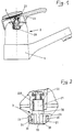
- a valve 1 is shown in part for arrangement on a washstand, etc. Through connection pipes, not shown in the drawing, the fitting 1 is supplied with cold water and hot water from the supply line network.
- a valve 2 is provided in the valve 1, the individual valve elements of which are encapsulated in a valve housing 20.
- An adjusting lever 21 made of square material is axially guided out of the valve housing 20, to which a handle 22 is fastened with the interposition of an insulating bushing 220.
- the handle 22 is movable in two degrees of freedom. By turning the handle 22 about the vertical axis, the mixing ratio of the incoming cold and hot water, with a pivoting about the horizontal axis, the water flow rate of the valve 2 can be adjusted.
- fixed stops 23 are formed on the valve housing 20, against which the actuating lever 21 rests in the maximum open position or the closed position of the valve 2, as can be seen in particular from FIG. 2 of the drawing.
- a wedge element 3 can be arranged between the actuating lever 21 and the fixed stop 23 .
- the wedge element 3 is integrally formed on a sleeve 30 which comprises the adjusting lever 21.
- the sleeve 30 with the wedge element 3 is axially supported on the one hand with side cheeks 33 in the region of the horizontal pivot axis on the housing 20 and on the other hand is secured in the plug-in position by the handle 22 with the insulating bushing 220.
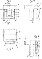
- the wedge element 3, as can be seen in particular from FIGS. 3 to 6, is formed in one piece with the sleeve 30 and the side cheeks 33 and is made of plastic by injection molding.
- the wedge element 3 consists of a higher wedge 31, which is guided as a U-shaped bracket around a flatter wedge (32), as can be seen in particular from FIGS. 3 and 6.
- the U-shaped bracket of the higher wedge 31 is provided in the region of the transition to the sleeve 30 with predetermined breaking points 34 designed as grooves, so that the higher bracket 31 can optionally be broken off.
- the wedge element can be installed in the following way: In the case of an already installed fitting 1, the handle 22 with the insulating bush 220 is first removed from the actuating lever 21 of the valve 2. Now the wedge element 3 with the sleeve 30 can be slid over the adjusting lever 21 until the side cheeks 33 come into contact with the valve housing 20. The handle 22 can then be fastened again to the actuating lever 21 with the insulating bushing 220. According to this, the maximum flow limitation is effective or the wedge element 3 prevents the originally possible maximum opening of the valve 2 with the wedge 31.
- the wedge element 3 can be removed again the wedge 31 is broken off at the predetermined breaking points 34 and then the wedge element 3 is reinstalled, so that in this version the flow restriction is reduced or the maximum flow rate is increased.
- three different maximum flow positions of the actuating lever 21 can be determined, namely, a relatively strong throttling with the wedge 31, a lower throttling with the wedge 32 and no throttling at all without the wedge element 3.
- the wedge element 3 can of course also be installed in the factory when the valve 1 is fully assembled, in addition to the subsequent installation in already installed valves.
- the sleeve 30 is not slotted, so that it can only be pushed axially onto the adjusting lever 21.
- the sleeve can also be slotted on the end face facing away from the wedge element 3, so that it can also be snapped onto the adjusting lever 21 laterally.
Abstract
Description
Die Erfindung betrifft ein Ventil mit den im Oberbegriff des Anspruchs 1 angegebenen Merkmalen. Ein derartiges Ventil ist aus der Druckschrift GB-A-2 110 240 bekannt. Hierbei ist eine Anschlaghülse, die stirnseitig angeordnete Anschlagstufen aufweist, auf einem verzahnten Teil eines Stellhebels angeordnet.
In der nicht vorveröffentlichten Druckschrift EP-A-0 568 013 ist außerdem ein Ventil gezeigt, bei dem eine auf einem Stellhebel angeordnete Buchse vorgesehen ist, an der an der einen Stirnseite mehrere Vorsprünge zur Schwenkbegrenzung ausgebildet sind.
Schließlich ist aus der deutschen Offenlegungsschrift DE-A 32 44 121 ein Ventil bekannt, bei dem in dem Stellhebel in einer quer angeordneten Gewindebohrung ein Gewindestift vorgesehen ist. Der Gewindestift kann radial aus dem Stellhebel herausgedreht werden, so daß die vorstehende Stirnfläche des Gewindestiftes mit der an dem Ventilgehäuse ausgebildeten Anschlagfläche zusammenwirkt. Durch ein entsprechendes Herausdrehen des Gewindestiftes kann somit die maximale Öffnung des Ventils und damit die maximal mögliche Durchflußmenge verringert werden.
Diese vorveröffentlichten Durchflußbegrenzungsausbildungen lassen sich jedoch nicht oder nur sehr schwer bei bereits installierten Ventilen einsetzen.The invention relates to a valve with the features specified in the preamble of claim 1. Such a valve is known from GB-A-2 110 240. Here, a stop sleeve, which has stop stages arranged on the end face, is arranged on a toothed part of an actuating lever.
In the unpublished publication EP-A-0 568 013 there is also shown a valve in which a bushing is provided on an actuating lever, on which a plurality of projections for swiveling limitation are formed on one end face.
Finally, from the German patent application DE-A 32 44 121 a valve is known in which a set screw is provided in the adjusting lever in a transverse threaded bore. The grub screw can be turned radially out of the adjusting lever so that the projecting end face of the grub screw interacts with the stop surface formed on the valve housing. By appropriately unscrewing the threaded pin, the maximum opening of the valve and thus the maximum possible flow rate can be reduced.
However, these previously published flow limitation designs cannot be used or can only be used with great difficulty with valves which are already installed.
Der Erfindung liegt die Aufgabe zugrunde, bei einem Ventil nach dem Oberbegriff des Anspruchs 1 eine Durchflußbegrenzungseinrichtung zu schaffen, die auch nachträglich an dem Ventil einsetzbar ist und die kostengünstig hergestellt werden kann.The invention has for its object to provide a flow limiting device in a valve according to the preamble of claim 1, which can also be used retrospectively on the valve and which can be manufactured inexpensively.
Diese Aufgabe wird erfindungsgemäß mit den Merkmalen des Anspruchs 1 gelöst.
Weitere Ausgestaltungen der Erfindung sind in den Ansprüchen 2 bis 4 angegeben.This object is achieved with the features of claim 1.
Further refinements of the invention are specified in
Mit diesen Maßnahmen kann auch nachträglich der Schwenkbereich des Stellhebels mit einfachen Mitteln begrenzt werden.With these measures, the pivoting range of the actuating lever can also be subsequently limited with simple means.
Ein Ausführungsbeispiel der Erfindung ist in der Zeichnung dargestellt und wird im folgenden näher beschrieben. Es zeigt
- Figur 1
- eine Armatur für einen Waschtisch mit einem Ventil zur Wassermischung und -dosierung mit Eingriffbedienung teilweise geschnitten;
Figur 2- einen Teil der in Figur 1 gezeigten Griffausbildung in vergrößerter Darstellung im Längsschnitt;
Figur 3- ein Keilelement in Vorderansicht in vergrößerter Darstellung;
- Figur 4
- das in
Figur 3 gezeigte Keilelement in Seitenansicht; - Figur 5
- das in
Figur 3 gezeigte Keilelement in Draufsicht; - Figur 6
- das in
Figur 3 gezeigte Keilelement in der Schnittebene VI.
- Figure 1
- a fitting for a washstand with a valve for water mixing and dosing with one-touch operation partially cut;
- Figure 2
- a part of the handle training shown in Figure 1 in an enlarged view in longitudinal section;
- Figure 3
- a wedge element in front view in an enlarged view;
- Figure 4
- the wedge element shown in Figure 3 in side view;
- Figure 5
- the wedge element shown in Figure 3 in plan view;
- Figure 6
- the wedge element shown in Figure 3 in the section plane VI.
In Figur 1 ist eine zum Teil dargestellte Armatur 1 für die Anordnung auf einem Waschtisch etc. gezeigt. Durch in der Zeichnung nicht dargestellte Anschlußrohre wird der Armatur 1 Kaltwasser und Warmwasser vom Versorgungsleitungsnetz zugeführt. In der Armatur 1 ist ein Ventil 2 vorgesehen, dessen einzelne Ventilelemente in einem Ventilgehäuse 20 gekapselt angeordnet sind. Aus dem Ventilgehäuse 20 ist axial ein aus Vierkantmaterial hergestellter Stellhebel 21 herausgeführt, an dem unter Zwischenlage einer Isolierbuchse 220 ein Griff 22 befestigt ist. Der Griff 22 ist in zwei Freiheitsgraden bewegbar. Mit einem Drehen des Griffs 22 um die vertikale Achse kann das Mischungsverhältnis des zufließenden Kalt- und Warmwassers, mit einem Schwenken um die horizontale Achse die Wasserdurchflußmenge des Ventils 2 eingestellt werden. Zur Begrenzung der Schwenkbewegung um die horizontale Achse sind Festanschläge 23 an dem Ventilgehäuse 20 ausgebildet, an denen der Stellhebel 21 in der maximalen Öffnungsposition oder der Schließposition des Ventils 2 anliegt, wie es insbesondere aus Figur 2 der Zeichnung zu entnehmen ist.In Figure 1, a valve 1 is shown in part for arrangement on a washstand, etc. Through connection pipes, not shown in the drawing, the fitting 1 is supplied with cold water and hot water from the supply line network. A
Zur wahlweisen Begrenzung der Maximalöffnung des Ventils 2 bzw. Begrenzung der maximalen Durchflußmenge kann zwischen dem Stellhebel 21 und dem Festanschlag 23 ein Keilelement 3 angeordnet werden. Das Keilelement 3 ist an einer Hülse 30 angeformt, welche den Stellhebel 21 umfaßt. Die Hülse 30 mit dem Keilelement 3 ist axial einerseits mit Seitenwangen 33 im Bereich der horizontalen Schwenkachse am Gehäuse 20 abgestützt und wird andererseits von dem Griff 22 mit der Isolierbuchse 220 in der Stecklage gesichert.
Das Keilelement 3 ist, wie es insbesondere aus den Figuren 3 bis 6 ersichtlich ist, einstückig mit der Hülse 30 und den Seitenwangen 33 ausgebildet und aus Kunststoff im Spritzgießverfahren hergestellt. Das Keilelement 3 besteht dabei aus einem höheren Keil 31, der als U-förmiger Bügel um einen flacheren Keil (32) herumgeführt ist, wie es insbesondere aus Figur 3 und 6 zu entnehmen ist. Der U-förmige Bügel des höheren Keils 31 ist hierbei im Bereich des Übergangs zur Hülse 30 mit als Hohlkehlen ausgebildeten Sollbruchstellen 34 versehen, so daß der höhere Bügel 31 wahlweise abgebrochen werden kann.To selectively limit the maximum opening of the
The
Die Montage des Keilelements kann in folgender Weise vorgenommen werden:
Bei einer bereits installierten Armatur 1 wird zunächst der Griff 22 mit der Isolierbuchse 220 von dem Stellhebel 21 des Ventils 2 abgenommen. Nunmehr kann das Keilelement 3 mit der Hülse 30 über den Stellhebel 21 gestreift werden, bis die Seitenwangen 33 an dem Ventilgehäuse 20 zur Anlage gelangen. Sodann kann erneut der Griff 22 mit der Isolierbuchse 220 an dem Stellhebel 21 befestigt werden. Hiernach ist die maximale Durchflußbegrenzung wirksam bzw. das Keilelement 3 verhindert mit dem Keil 31 die ursprünglich mögliche maximale Öffnung des Ventils 2. Sollte der Keil 31 eine zu starke Drosselung des Durchflusses bewirken, so kann nach einem nochmaligen Herausnehmen des Keilelements 3 der Keil 31 an den Sollbruchstellen 34 abgebrochen werden und danach das Keilelement 3 erneut eingebaut werden, so daß in dieser Version die Durchflußdrosselung verringert bzw. die maximale Durchflußmenge vergrößert wird.
Somit können drei verschiedene Maximaldurchflußpositionen des Stellhebels 21 bestimmt werden, nämlich, mit dem Keil 31 wird eine relativ starke Drosselung, mit dem Keil 32 eine geringere Drosselung und ohne Keilelement 3 überhaupt keine Drosselung vorgenommen.
Das Keilelement 3 kann selbstverständlich neben dem nachträglichen Einbau in bereits installierten Armaturen auch werksseitig bei der Fertigmontage der Armatur 1 mit einmontiert werden.The wedge element can be installed in the following way:
In the case of an already installed fitting 1, the
Thus, three different maximum flow positions of the actuating
The
Bei dem vorstehend aufgeführten Keilelement 3 ist die Hülse 30 ungeschlitzt ausgebildet, so daß es nur axial auf den Stellhebel 21 aufgeschoben werden kann. Selbstverständlich kann aber auch die Hülse an der vom Keilelement 3 abgekehrten Stirnseite geschlitzt ausgebildet werden, so daß sie auch seitlich auf den Stellhebel 21 aufgeschnappt werden kann.In the
Claims (4)
- Valve having a valve housing (20), from which there extends an adjusting lever (21), which can be swivelled around a horizontal axis, for the determination of at least the flow, there being provided for limiting, as desired, the maximum flow per unit of time a special stop arrangement comprising a stop sleeve (30), which can be pushed over the adjusting lever (21) and can be fixed in the mounted position and corresponds with a fixed stop (23) of the valve housing (20) and is retained in one direction axially by a handle (22) arranged on the adjusting lever (21), characterised in that the sleeve (30) bears a wedge element (3) and is provided with at least one lateral limb (33), which supports the sleeve (30) on the valve housing (20) in the other direction axially in the region of the horizontal axis, the wedge element (3) abutting the adjusting lever (21) with one wedge surface, while the other wedge surface works together with the fixed stop (23) formed on an internal face of the valve housing (20).
- Valve according to claim 1, characterised in that the sleeve (30) is of slit construction on the side remote from the wedge element (3), so that the sleeve (30), together with the wedge element (3), can be snapped radially onto the adjusting lever (21).
- Valve according to claim 1 or claim 2, characterised in that the wedge element (3) is provided with two wedges (31, 32) of differing height in such a manner that the higher wedge (31), in the form of a U-shaped hoop, surrounds the flatter wedge (32), it being possible to break off the U-shaped, higher wedge (31) by means of predetermined breaking points (34), so that one of the two wedges (31, 32), as desired, comes into effect as flow limiter.
- Valve according to any one of claims 1 to 3, characterised in that the wedge element (3) or the sleeve (30) in one piece with the wedge element (3) is produced from plastics by injection moulding.
Applications Claiming Priority (2)
| Application Number | Priority Date | Filing Date | Title |
|---|---|---|---|
| DE4303191A DE4303191A1 (en) | 1993-02-04 | 1993-02-04 | Valve with lever stop |
| DE4303191 | 1993-02-04 |
Publications (2)
| Publication Number | Publication Date |
|---|---|
| EP0609720A1 EP0609720A1 (en) | 1994-08-10 |
| EP0609720B1 true EP0609720B1 (en) | 1997-10-01 |
Family
ID=6479632
Family Applications (1)
| Application Number | Title | Priority Date | Filing Date |
|---|---|---|---|
| EP94100853A Expired - Lifetime EP0609720B1 (en) | 1993-02-04 | 1994-01-21 | Valve with working lever stop |
Country Status (5)
| Country | Link |
|---|---|
| EP (1) | EP0609720B1 (en) |
| AT (1) | ATE158848T1 (en) |
| DE (2) | DE4303191A1 (en) |
| DK (1) | DK0609720T3 (en) |
| ES (2) | ES2110129T3 (en) |
Cited By (2)
| Publication number | Priority date | Publication date | Assignee | Title |
|---|---|---|---|---|
| DE102009008564A1 (en) | 2009-02-12 | 2010-08-19 | Grohe Ag | Sanitary armature for valve cartouche, has handle, mixing valve, housing and control disk which moves translator to valve disk, where control disk and valve disk have water passage openings, and control lever is provided in rotating sleeve |
| DE102011115390A1 (en) | 2011-10-10 | 2013-04-11 | Grohe Ag | Flow rate adjusting device e.g. valve for sanitary fitting, has driver element whose distance with respect to bearing point of actuating lever is varied within range of movement of lever |
Families Citing this family (2)
| Publication number | Priority date | Publication date | Assignee | Title |
|---|---|---|---|---|
| IT1281653B1 (en) * | 1995-11-03 | 1998-02-20 | Galatron Srl | FLOW LIMIT DEVICE FOR HOT AND COLD WATER MIXING VALVES |
| DE102005020990B4 (en) * | 2005-05-03 | 2012-07-12 | Grohe Ag | Valve with applicable flow rate limitation |
Family Cites Families (6)
| Publication number | Priority date | Publication date | Assignee | Title |
|---|---|---|---|---|
| CH654638A5 (en) * | 1981-11-26 | 1986-02-28 | Karrer Weber & Cie Ag | SANITARY SINGLE LEVER MIXER TAP. |
| DE3211619C2 (en) * | 1982-03-30 | 1986-12-04 | Heinrich Schulte & Sohn Gmbh & Co Kg, 5860 Iserlohn | Single lever mixer tap |
| DE3244121A1 (en) * | 1982-11-29 | 1984-05-30 | Friedrich Grohe Armaturenfabrik Gmbh & Co, 5870 Hemer | SANITARY MIXING VALVE |
| DE3426480A1 (en) * | 1984-07-18 | 1986-01-30 | Grohe Armaturen Friedrich | Safety mixing valve |
| BE1003580A3 (en) * | 1989-10-31 | 1992-04-28 | Staar Sa | Adjusting device for flow valve. |
| IT1260746B (en) * | 1992-04-30 | 1996-04-22 | Orlando Bosio | FLOW RATE DELIVERY DEVICE IN SINGLE-LEVER MIXING CARTRIDGE FOR HOT AND COLD WATER |
-
1993
- 1993-02-04 DE DE4303191A patent/DE4303191A1/en not_active Withdrawn
-
1994
- 1994-01-21 DE DE59404179T patent/DE59404179D1/en not_active Expired - Fee Related
- 1994-01-21 ES ES94100853T patent/ES2110129T3/en not_active Expired - Lifetime
- 1994-01-21 EP EP94100853A patent/EP0609720B1/en not_active Expired - Lifetime
- 1994-01-21 DK DK94100853.4T patent/DK0609720T3/en active
- 1994-01-21 AT AT94100853T patent/ATE158848T1/en not_active IP Right Cessation
- 1994-01-31 ES ES09400242U patent/ES1026964Y/en not_active Expired - Lifetime
Cited By (4)
| Publication number | Priority date | Publication date | Assignee | Title |
|---|---|---|---|---|
| DE102009008564A1 (en) | 2009-02-12 | 2010-08-19 | Grohe Ag | Sanitary armature for valve cartouche, has handle, mixing valve, housing and control disk which moves translator to valve disk, where control disk and valve disk have water passage openings, and control lever is provided in rotating sleeve |
| DE102009008564B4 (en) * | 2009-02-12 | 2011-03-10 | Grohe Ag | plumbing fixture |
| DE102011115390A1 (en) | 2011-10-10 | 2013-04-11 | Grohe Ag | Flow rate adjusting device e.g. valve for sanitary fitting, has driver element whose distance with respect to bearing point of actuating lever is varied within range of movement of lever |
| DE102011115390B4 (en) | 2011-10-10 | 2019-02-14 | Grohe Ag | Flow rate adjustment device for a sanitary fitting |
Also Published As
| Publication number | Publication date |
|---|---|
| EP0609720A1 (en) | 1994-08-10 |
| ES1026964Y (en) | 1995-02-16 |
| ES2110129T3 (en) | 1998-02-01 |
| DE4303191A1 (en) | 1994-08-11 |
| ATE158848T1 (en) | 1997-10-15 |
| DK0609720T3 (en) | 1998-04-14 |
| ES1026964U (en) | 1994-06-16 |
| DE59404179D1 (en) | 1997-11-06 |
Similar Documents
| Publication | Publication Date | Title |
|---|---|---|
| EP0662577B1 (en) | Actuating device for a single-lever mixing valve | |
| EP0646688B1 (en) | Door handle especially for a vehicle door | |
| DE3612988A1 (en) | MIXED BATTERY | |
| DE3300624A1 (en) | VALVE WITH PRESET THE FLOW RATE | |
| DE3613854C1 (en) | Switching device | |
| EP1193432B1 (en) | Valve, in particular radiator valve | |
| EP0609720B1 (en) | Valve with working lever stop | |
| EP1239496B1 (en) | Hinge with switch | |
| DE102006012304B4 (en) | lever valve | |
| DE3428286C2 (en) | ||
| DE4407373A1 (en) | Pre=adjustable control thermostatic valve for hot water heater unit | |
| EP0137154B1 (en) | Multiple-way cock | |
| DE3041816C2 (en) | ||
| DE102005001303A1 (en) | Sanitary distribution valve for switching between water outlets has at least one inlet and two outlets, adjustable control device and adjustment limitation | |
| DE2944520A1 (en) | VALVE PART | |
| EP0932175B1 (en) | Pivotable actuator for safety switch | |
| DE3426480C2 (en) | ||
| EP0100468A2 (en) | Pivot bearing for doors, especially for swinging doors | |
| DE3535176C2 (en) | ||
| DE3219574A1 (en) | Single-lever mixer fitting | |
| EP0787880A1 (en) | Height adjusting device for a lower finishing part of doors or windows | |
| DE3644182A1 (en) | Shut-off device | |
| DE3305417C1 (en) | Adjusting device for mechanical connections incorporating pulling and pushing means | |
| DE3034619A1 (en) | Tilt and turn window or door corner bearing - has widened sections adjoining threaded pin faces fitting jaw recesses with min. play | |
| DE2231702A1 (en) | LIQUID TAP |
Legal Events
| Date | Code | Title | Description |
|---|---|---|---|
| PUAI | Public reference made under article 153(3) epc to a published international application that has entered the european phase |
Free format text: ORIGINAL CODE: 0009012 |
|
| AK | Designated contracting states |
Kind code of ref document: A1 Designated state(s): AT CH DE DK ES FR GB IT LI SE |
|
| 17P | Request for examination filed |
Effective date: 19940824 |
|
| 17Q | First examination report despatched |
Effective date: 19951006 |
|
| GRAG | Despatch of communication of intention to grant |
Free format text: ORIGINAL CODE: EPIDOS AGRA |
|
| GRAH | Despatch of communication of intention to grant a patent |
Free format text: ORIGINAL CODE: EPIDOS IGRA |
|
| GRAH | Despatch of communication of intention to grant a patent |
Free format text: ORIGINAL CODE: EPIDOS IGRA |
|
| GRAA | (expected) grant |
Free format text: ORIGINAL CODE: 0009210 |
|
| AK | Designated contracting states |
Kind code of ref document: B1 Designated state(s): AT CH DE DK ES FR GB IT LI SE |
|
| REF | Corresponds to: |
Ref document number: 158848 Country of ref document: AT Date of ref document: 19971015 Kind code of ref document: T |
|
| REG | Reference to a national code |
Ref country code: CH Ref legal event code: EP |
|
| REF | Corresponds to: |
Ref document number: 59404179 Country of ref document: DE Date of ref document: 19971106 |
|
| ET | Fr: translation filed | ||
| REG | Reference to a national code |
Ref country code: CH Ref legal event code: NV Representative=s name: BOVARD AG PATENTANWAELTE |
|
| ITF | It: translation for a ep patent filed |
Owner name: STUDIO JAUMANN P. & C. S.N.C. |
|
| GBT | Gb: translation of ep patent filed (gb section 77(6)(a)/1977) |
Effective date: 19971219 |
|
| REG | Reference to a national code |
Ref country code: ES Ref legal event code: FG2A Ref document number: 2110129 Country of ref document: ES Kind code of ref document: T3 |
|
| REG | Reference to a national code |
Ref country code: DK Ref legal event code: T3 |
|
| PLBE | No opposition filed within time limit |
Free format text: ORIGINAL CODE: 0009261 |
|
| STAA | Information on the status of an ep patent application or granted ep patent |
Free format text: STATUS: NO OPPOSITION FILED WITHIN TIME LIMIT |
|
| 26N | No opposition filed | ||
| PGFP | Annual fee paid to national office [announced via postgrant information from national office to epo] |
Ref country code: SE Payment date: 19981221 Year of fee payment: 6 |
|
| PGFP | Annual fee paid to national office [announced via postgrant information from national office to epo] |
Ref country code: FR Payment date: 19981230 Year of fee payment: 6 |
|
| PGFP | Annual fee paid to national office [announced via postgrant information from national office to epo] |
Ref country code: DK Payment date: 19990115 Year of fee payment: 6 |
|
| PGFP | Annual fee paid to national office [announced via postgrant information from national office to epo] |
Ref country code: CH Payment date: 19990118 Year of fee payment: 6 |
|
| PGFP | Annual fee paid to national office [announced via postgrant information from national office to epo] |
Ref country code: GB Payment date: 19990121 Year of fee payment: 6 |
|
| PGFP | Annual fee paid to national office [announced via postgrant information from national office to epo] |
Ref country code: AT Payment date: 19990126 Year of fee payment: 6 |
|
| PGFP | Annual fee paid to national office [announced via postgrant information from national office to epo] |
Ref country code: ES Payment date: 19990129 Year of fee payment: 6 |
|
| PG25 | Lapsed in a contracting state [announced via postgrant information from national office to epo] |
Ref country code: GB Free format text: LAPSE BECAUSE OF NON-PAYMENT OF DUE FEES Effective date: 20000121 Ref country code: DK Free format text: LAPSE BECAUSE OF NON-PAYMENT OF DUE FEES Effective date: 20000121 Ref country code: AT Free format text: LAPSE BECAUSE OF NON-PAYMENT OF DUE FEES Effective date: 20000121 |
|
| PG25 | Lapsed in a contracting state [announced via postgrant information from national office to epo] |
Ref country code: SE Free format text: LAPSE BECAUSE OF NON-PAYMENT OF DUE FEES Effective date: 20000122 Ref country code: ES Free format text: LAPSE BECAUSE OF NON-PAYMENT OF DUE FEES Effective date: 20000122 |
|
| PG25 | Lapsed in a contracting state [announced via postgrant information from national office to epo] |
Ref country code: LI Free format text: LAPSE BECAUSE OF NON-PAYMENT OF DUE FEES Effective date: 20000131 Ref country code: CH Free format text: LAPSE BECAUSE OF NON-PAYMENT OF DUE FEES Effective date: 20000131 |
|
| EUG | Se: european patent has lapsed |
Ref document number: 94100853.4 |
|
| GBPC | Gb: european patent ceased through non-payment of renewal fee |
Effective date: 20000121 |
|
| REG | Reference to a national code |
Ref country code: CH Ref legal event code: PL |
|
| PG25 | Lapsed in a contracting state [announced via postgrant information from national office to epo] |
Ref country code: FR Free format text: LAPSE BECAUSE OF NON-PAYMENT OF DUE FEES Effective date: 20000929 |
|
| REG | Reference to a national code |
Ref country code: DK Ref legal event code: EBP |
|
| REG | Reference to a national code |
Ref country code: FR Ref legal event code: ST |
|
| PGFP | Annual fee paid to national office [announced via postgrant information from national office to epo] |
Ref country code: DE Payment date: 20010123 Year of fee payment: 8 |
|
| REG | Reference to a national code |
Ref country code: ES Ref legal event code: FD2A Effective date: 20010910 |
|
| PG25 | Lapsed in a contracting state [announced via postgrant information from national office to epo] |
Ref country code: DE Free format text: LAPSE BECAUSE OF NON-PAYMENT OF DUE FEES Effective date: 20020801 |
|
| PG25 | Lapsed in a contracting state [announced via postgrant information from national office to epo] |
Ref country code: IT Free format text: LAPSE BECAUSE OF NON-PAYMENT OF DUE FEES;WARNING: LAPSES OF ITALIAN PATENTS WITH EFFECTIVE DATE BEFORE 2007 MAY HAVE OCCURRED AT ANY TIME BEFORE 2007. THE CORRECT EFFECTIVE DATE MAY BE DIFFERENT FROM THE ONE RECORDED. Effective date: 20050121 |