DE102009008564B4 - plumbing fixture - Google Patents
plumbing fixture Download PDFInfo
- Publication number
- DE102009008564B4 DE102009008564B4 DE200910008564 DE102009008564A DE102009008564B4 DE 102009008564 B4 DE102009008564 B4 DE 102009008564B4 DE 200910008564 DE200910008564 DE 200910008564 DE 102009008564 A DE102009008564 A DE 102009008564A DE 102009008564 B4 DE102009008564 B4 DE 102009008564B4
- Authority
- DE
- Germany
- Prior art keywords
- sanitary fitting
- handle
- fitting according
- lever
- stop element
- Prior art date
- Legal status (The legal status is an assumption and is not a legal conclusion. Google has not performed a legal analysis and makes no representation as to the accuracy of the status listed.)
- Expired - Fee Related
Links
Images
Classifications
-
- F—MECHANICAL ENGINEERING; LIGHTING; HEATING; WEAPONS; BLASTING
- F16—ENGINEERING ELEMENTS AND UNITS; GENERAL MEASURES FOR PRODUCING AND MAINTAINING EFFECTIVE FUNCTIONING OF MACHINES OR INSTALLATIONS; THERMAL INSULATION IN GENERAL
- F16K—VALVES; TAPS; COCKS; ACTUATING-FLOATS; DEVICES FOR VENTING OR AERATING
- F16K31/00—Actuating devices; Operating means; Releasing devices
- F16K31/44—Mechanical actuating means
- F16K31/60—Handles
- F16K31/605—Handles for single handle mixing valves
Abstract
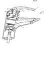
Sanitärarmatur (1) mit
– einem Handgriff (2) und
– einem Mischventil (3),
– das ein Gehäuse,
– eine in dem Gehäuse angeordnete Ventilsitzscheibe und
– eine translatorisch zur Ventilsitzscheibe bewegbare Steuerscheibe umfasst,
– wobei die Ventilsitzscheibe und die Steuerscheibe Wasserdurchlassöffnungen aufweisen, die in Überschneidung gebracht werden können und zur Steuerung der Durchflussmenge ein zumindest um eine horizontale Achse (12) verschwenkbarer Stellhebel (4), der in Wirkverbindung zur Steuerscheibe steht, in einer drehbaren Hülse (5) vorgesehen ist,
dadurch gekennzeichnet, dass zur Kopplung des Stellhebels (4) mit dem Handgriff (2) ein Verbindungselement (6) vorgesehen ist, das eine Aufnahme (7) mit einem darin angeordneten stufenlos verstellbaren Anschlagelement (8) aufweist.Sanitary fitting (1) with
- a handle (2) and
A mixing valve (3),
- a housing,
- In the housing arranged valve seat disc and
Comprising a control disc movable in translation relative to the valve seat disc,
- wherein the valve seat disc and the control disk have water passage openings which can be brought into overlap and for controlling the flow rate at least about a horizontal axis (12) pivotable adjusting lever (4), which is in operative connection to the control disk, in a rotatable sleeve (5) is provided,
characterized in that for coupling the adjusting lever (4) with the handle (2) a connecting element (6) is provided which has a receptacle (7) with a continuously adjustable stop element (8) arranged therein.
Description
Die Erfindung betrifft eine Sanitärarmatur gemäß dem Oberbegriff des Patentanspruchs 1.The invention relates to a sanitary fitting according to the preamble of patent claim 1.
Sanitärarmaturen dieser Art, so genannte Einhebel-Mischbatterien sind, bekannt. Die Schwenkbewegung des mit dem Handgriff verbundenen Stellhebels ist dabei durch die Ausformung des Mischventilgehäuses definiert. Üblicherweise sind die Handgriffe der Armatur dabei mit dem Stellhebel verschraubt. Soll bei der Betätigung des Handgriffs der Sanitärarmatur eine bestimmte Durchflussmenge an Wasser nicht überschritten werden, sind zusätzliche konstruktive Maßnahmen erforderlich, mit denen beispielsweise die Schwenkbewegung des Stellhebels begrenzt werden kann.Sanitary fittings of this type, so-called single-lever mixers are known. The pivoting movement of the actuating lever connected to the handle is defined by the shape of the mixing valve housing. Usually, the handles of the fitting are screwed to the adjusting lever. If, during operation of the handle of the sanitary fitting, a certain flow rate of water is not exceeded, additional design measures are required with which, for example, the pivotal movement of the control lever can be limited.
Aus der
Die Druckschrift
Auch aus der
Durch die
Schließlich zeigt die
Vor diesem Hintergrund besteht die Aufgabe der Erfindung darin, die Ausbildung einer Sanitärarmatur mit einem Einhebelmischventil zu vereinfachen und dabei die Schwenkbewegung bzw. den Stellweg des zugehörigen Stellhebels wählbar zu gestalten.Against this background, the object of the invention is to simplify the formation of a sanitary fitting with a Einhebelmischventil while making the pivotal movement and the travel of the associated control lever selectable.
Die Aufgabe wird durch eine Sanitärarmatur mit den Merkmalen des Patentanspruchs 1 gelöst. Vorteilhafte Ausgestaltungen der Erfindung sind Gegenstand von Unteransprüchen.The object is achieved by a sanitary fitting with the features of claim 1. Advantageous embodiments of the invention are the subject of dependent claims.
Mit der Erfindung wird eine Sanitärarmatur mit einem Handgriff und einem Mischventil, das ein Gehäuse, eine in dem Gehäuse angeordnete Ventilsitzscheibe und eine translatorisch zur Ventilsitzscheibe bewegbare Steuerscheibe umfasst, bereit gestellt, wobei die Ventilsitzscheibe und die Steuerscheibe eine oder mehrere Wasserdurchlassöffnungen aufweisen, die in Überschneidung gebracht werden können und zur Steuerung der Durchflussmenge ein zumindest um eine horizontale Achse verschwenkbarer Stellhebel, der in Wirkverbindung zur Steuerscheibe steht, in einer drehbaren Hülse vorgesehen ist. Zur Kopplung des Stellhebels mit dem Handgriff ist dabei ein Verbindungselement angeordnet, das eine Aufnahme für ein Anschlagelement aufweist.The invention provides a sanitary fitting with a handle and a mixing valve, which comprises a housing, a valve seat disk arranged in the housing and a control disk movable in translation relative to the valve seat disk, wherein the valve seat disk and the control disk have one or more water passage openings that overlap can be brought and for controlling the flow rate at least about a horizontal axis pivotable adjusting lever which is operatively connected to the control disk, is provided in a rotatable sleeve. For coupling the adjusting lever with the handle while a connecting element is arranged, which has a receptacle for a stop element.
Ein besonderer Vorteil der Erfindung besteht darin, dass somit eine Vorrichtung zur Durchflussmengenbegrenzung in das Verbindungselement integriert werden kann, ohne dass an dem Mischventil Änderungen gegenüber einem Mischventil ohne Mengenbegrenzung vorgenommen werden müssen. Das Verbindungselement ist für beide Arten von Mischventilen baugleich ausgeführt. In der Aufnahme des Verbindungselements kann somit wahlweise ein Anschlagelement angeordnet werden oder nicht.A particular advantage of the invention is that thus a device for limiting the flow rate can be integrated into the connecting element, without having to be made to the mixing valve changes compared to a mixing valve without quantity limitation. The connecting element is designed identical for both types of mixing valves. In the receptacle of the connecting element can thus optionally be arranged a stop element or not.
Das Verbindungselement ist vorteilhafterweise form- und/oder kraftschlüssig mit dem Stellhebel und dem Handgriff verbunden. Da die Vorrichtung zur Durchflussmengenbegrenzung an dem Verbindungselement angeordnet ist und mit der drehbaren Hülse des Mischventilgehäuses zusammenwirkt, ist es nicht notwendig, den Stellhebel, welcher im Allgemeinen aus Metall besteht, zu bearbeiten, wodurch Kosten verursachende Bearbeitungsvorgänge, wie beispielsweise Schneiden von Gewinden oder Fräsen von Nuten, eingespart werden können. Weiterhin wird der Querschnitt des Stellhebels nicht geschwächt, so dass sich die konstruktiven Änderungen an der Sanitärarmatur für die Durchflussmengenbegrenzung nicht auf die Festigkeit des Stellhebels auswirken.The connecting element is advantageously positively and / or non-positively connected to the adjusting lever and the handle. Since the flow rate limiting device is arranged on the connecting element and cooperates with the rotatable sleeve of the mixing valve housing, it is not necessary to machine the adjusting lever, which is generally made of metal, whereby machining operations such as cutting threads or milling of machining costs are caused Grooves, can be saved. Furthermore, the cross-section of the control lever is not weakened, so that the structural changes to the sanitary fitting for the flow rate limit does not affect the strength of the control lever.
Wenn ein Anschlagelement wahlweise in der Aufnahme des Verbindungselements angeordnet ist, begrenzt dieses die Schwenkbewegung des Stellhebels in der Hülse. Der mögliche Weg des Stellhebels zwischen Schließposition des Mischventils und maximal geöffneter Position verringert sich dadurch, die Durchlassöffnungen von Ventilsitzscheibe und Steuerscheibe überschneiden sich nur teilweise und die Durchflussmenge an Wasser verringert sich entsprechend.If a stop element is optionally arranged in the receptacle of the connecting element, this limits the pivotal movement of the actuating lever in the sleeve. The possible path of the actuating lever between the closed position of the mixing valve and the maximum open position is thereby reduced, the passage openings of the valve seat disc and the control disc overlap only partially and the flow rate of water is reduced accordingly.
Eine Ausbildung der Erfindung sieht vor, dass das Anschlagelement eine Keilform aufweist. Zudem ist das Anschlagelement in der Aufnahme axial verschieblich gelagert. Damit ist das Anschlagelement in der Aufnahme stufenlos verstellbar, wodurch auch eine stufenlose Durchflussmengenbegrenzung ermöglicht wird. An embodiment of the invention provides that the stop element has a wedge shape. In addition, the stop element is mounted axially displaceably in the receptacle. Thus, the stop element in the receptacle is infinitely adjustable, whereby a stepless flow rate limitation is made possible.
Zur Fixierung der Position des Anschlagelementes in der Aufnahme wird diese mittels eines Stellelementes, beispielsweise einer Schraube eingestellt. Damit sich die Schraube nicht bei der Betätigung des Handgriffs bzw. des Stellhebels eigenständig verdrehen kann, sind entsprechende Sicherungsmittel am Verbindungselement vorgesehen.To fix the position of the stop element in the receptacle, this is adjusted by means of an adjusting element, for example a screw. So that the screw can not rotate independently when the handle or the actuating lever is actuated, corresponding securing means are provided on the connecting element.
Vorteilhafterweise weisen Anschlagelement und/oder Aufnahme des Verbindungselements eine Führung, vorzugsweise in Form einer Nut- und Federverbindung, auf.Advantageously, stop element and / or receptacle of the connecting element have a guide, preferably in the form of a tongue and groove connection.
Gemäß einer anderen Weiterbildung ist es vorteilhaft, dass das Verbindungselement eine Positionierungshilfe aufweist, welche im Handgriff eingreift. Dadurch wird eine einfache und toleranzarme Kopplung des Verbindungselements mit dem Handgriff ermöglicht.According to another embodiment, it is advantageous that the connecting element has a positioning aid which engages in the handle. This allows a simple and low-tolerance coupling of the connecting element with the handle.
Die Erfindung wird nachfolgend unter Bezugnahme auf die Zeichnungen näher erläutert. Darin zeigen im Einzelnen:The invention will be explained in more detail with reference to the drawings. In detail:
BezugszeichenlisteLIST OF REFERENCE NUMBERS
- 11
- Sanitärarmaturplumbing fixture
- 22
- Handgriffhandle
- 33
- Ventilkartuschevalve cartridge
- 44
- Stellhebellever
- 55
- Schwenkhülsepivoting sleeve
- 66
- Verbindungselementconnecting element
- 77
- Aufnahmeadmission
- 88th
- Anschlagelementstop element
- 99
- Stellelementactuator
- 1010
- PositionierungshilfePositionierungshilfe
- 1111
- Befestigungsschraubefixing screw
- 1212
- Drehachseaxis of rotation
- 1313
- Befestigungsmittelfastener
Claims (9)
Priority Applications (1)
| Application Number | Priority Date | Filing Date | Title |
|---|---|---|---|
| DE200910008564 DE102009008564B4 (en) | 2009-02-12 | 2009-02-12 | plumbing fixture |
Applications Claiming Priority (1)
| Application Number | Priority Date | Filing Date | Title |
|---|---|---|---|
| DE200910008564 DE102009008564B4 (en) | 2009-02-12 | 2009-02-12 | plumbing fixture |
Publications (2)
| Publication Number | Publication Date |
|---|---|
| DE102009008564A1 DE102009008564A1 (en) | 2010-08-19 |
| DE102009008564B4 true DE102009008564B4 (en) | 2011-03-10 |
Family
ID=42338628
Family Applications (1)
| Application Number | Title | Priority Date | Filing Date |
|---|---|---|---|
| DE200910008564 Expired - Fee Related DE102009008564B4 (en) | 2009-02-12 | 2009-02-12 | plumbing fixture |
Country Status (1)
| Country | Link |
|---|---|
| DE (1) | DE102009008564B4 (en) |
Families Citing this family (1)
| Publication number | Priority date | Publication date | Assignee | Title |
|---|---|---|---|---|
| DE102011115390B4 (en) | 2011-10-10 | 2019-02-14 | Grohe Ag | Flow rate adjustment device for a sanitary fitting |
Citations (5)
| Publication number | Priority date | Publication date | Assignee | Title |
|---|---|---|---|---|
| DE3337968A1 (en) * | 1983-10-19 | 1985-05-02 | Friedrich Grohe Armaturenfabrik Gmbh & Co, 5870 Hemer | HAND LEVER FOR HANDLE MIXING VALVES |
| EP0568013B1 (en) * | 1992-04-30 | 1996-02-07 | AMFAG S.r.l. | Flow-rate limiting device in a single-control mixer cartridge |
| EP0609720B1 (en) * | 1993-02-04 | 1997-10-01 | Friedrich Grohe Aktiengesellschaft | Valve with working lever stop |
| DE19736908A1 (en) * | 1997-08-25 | 1999-03-11 | Guido Dipl Ing Nohr | Sanitary fitting, particularly mixing valve |
| DE102005020990A1 (en) * | 2005-05-03 | 2006-11-16 | Grohe Ag | Valve has control lever for determining flow rate through it, sleeve fitted on lever having recess, into which shaft of wedge-shaped component fits which has transverse ribs which fit into transverse grooves in recess |
-
2009
- 2009-02-12 DE DE200910008564 patent/DE102009008564B4/en not_active Expired - Fee Related
Patent Citations (5)
| Publication number | Priority date | Publication date | Assignee | Title |
|---|---|---|---|---|
| DE3337968A1 (en) * | 1983-10-19 | 1985-05-02 | Friedrich Grohe Armaturenfabrik Gmbh & Co, 5870 Hemer | HAND LEVER FOR HANDLE MIXING VALVES |
| EP0568013B1 (en) * | 1992-04-30 | 1996-02-07 | AMFAG S.r.l. | Flow-rate limiting device in a single-control mixer cartridge |
| EP0609720B1 (en) * | 1993-02-04 | 1997-10-01 | Friedrich Grohe Aktiengesellschaft | Valve with working lever stop |
| DE19736908A1 (en) * | 1997-08-25 | 1999-03-11 | Guido Dipl Ing Nohr | Sanitary fitting, particularly mixing valve |
| DE102005020990A1 (en) * | 2005-05-03 | 2006-11-16 | Grohe Ag | Valve has control lever for determining flow rate through it, sleeve fitted on lever having recess, into which shaft of wedge-shaped component fits which has transverse ribs which fit into transverse grooves in recess |
Also Published As
| Publication number | Publication date |
|---|---|
| DE102009008564A1 (en) | 2010-08-19 |
Similar Documents
| Publication | Publication Date | Title |
|---|---|---|
| DE60209666T2 (en) | Concentric quarter-turn thermostatic cartridge with ceramic discs and a mixer tap containing them | |
| EP2387739B1 (en) | Electronically controllable mixing device for tap water | |
| EP3420430B1 (en) | Thermostat mixing valve | |
| DE1949318B2 (en) | MIXING VALVE | |
| EP3021023B1 (en) | Sanitary fitting with offset operating element tilt axis | |
| EP3074676B1 (en) | Sanitary fitting | |
| EP3062002B1 (en) | Upper part of a valve | |
| DE19834575C5 (en) | Rotary valve | |
| DE60008954T2 (en) | Safety gas valve arrangement for a cooking stove | |
| DE19812049B4 (en) | liquid valve | |
| DE102009008564B4 (en) | plumbing fixture | |
| EP1462692B1 (en) | Valve head | |
| EP2206939B1 (en) | Valve | |
| EP3217103A1 (en) | Valve insert for a radiator valve and radiator having radiator valve | |
| EP2418409A1 (en) | Rotary handle | |
| EP1435480B1 (en) | Sanitary fitting | |
| EP0499716A1 (en) | Single handle mixing valve for sanitary installation | |
| DE10202560A1 (en) | Combined thermostat and shower mixer valve, comprising mechanism facilitating manual regulation in case of partial breakdown | |
| DE2634721A1 (en) | Liq. tap adaptor fitting - has coaxial inlet and outlet with valve between rotated to distribute flow | |
| DE69932240T2 (en) | SEQUENTIAL CARTRIDGE FOR A MIXING DEVICE WHICH IS INTERCHANGEABLE WITH A THERMOSTATIC CARTRIDGE | |
| DE102006050664A1 (en) | Actuating unit for valve, has drive shaft coupled with valve closing element, and drive shaft has head part for coupling with valve closing element | |
| DE10305724B4 (en) | radiator connection | |
| DE202020106639U1 (en) | Sanitary outlet unit | |
| EP2917623B1 (en) | Single lever mixing cartridge | |
| DE60224029T2 (en) | Faucet with the outlet in the upper part of the housing |
Legal Events
| Date | Code | Title | Description |
|---|---|---|---|
| OP8 | Request for examination as to paragraph 44 patent law | ||
| 8125 | Change of the main classification |
Ipc: F16K 11/02 AFI20090212BHDE |
|
| R020 | Patent grant now final |
Effective date: 20110702 |
|
| R119 | Application deemed withdrawn, or ip right lapsed, due to non-payment of renewal fee |