EP0609164B1 - Automatic filter press plate separating device - Google Patents
Automatic filter press plate separating device Download PDFInfo
- Publication number
- EP0609164B1 EP0609164B1 EP94460002A EP94460002A EP0609164B1 EP 0609164 B1 EP0609164 B1 EP 0609164B1 EP 94460002 A EP94460002 A EP 94460002A EP 94460002 A EP94460002 A EP 94460002A EP 0609164 B1 EP0609164 B1 EP 0609164B1
- Authority
- EP
- European Patent Office
- Prior art keywords
- plates
- carriage
- plate
- dismantling
- arms
- Prior art date
- Legal status (The legal status is an assumption and is not a legal conclusion. Google has not performed a legal analysis and makes no representation as to the accuracy of the status listed.)
- Expired - Lifetime
Links
Images


Classifications
-
- B—PERFORMING OPERATIONS; TRANSPORTING
- B01—PHYSICAL OR CHEMICAL PROCESSES OR APPARATUS IN GENERAL
- B01D—SEPARATION
- B01D25/00—Filters formed by clamping together several filtering elements or parts of such elements
- B01D25/12—Filter presses, i.e. of the plate or plate and frame type
- B01D25/164—Chamber-plate presses, i.e. the sides of the filtering elements being clamped between two successive filtering plates
-
- B—PERFORMING OPERATIONS; TRANSPORTING
- B01—PHYSICAL OR CHEMICAL PROCESSES OR APPARATUS IN GENERAL
- B01D—SEPARATION
- B01D25/00—Filters formed by clamping together several filtering elements or parts of such elements
- B01D25/12—Filter presses, i.e. of the plate or plate and frame type
- B01D25/172—Plate spreading means
-
- B—PERFORMING OPERATIONS; TRANSPORTING
- B01—PHYSICAL OR CHEMICAL PROCESSES OR APPARATUS IN GENERAL
- B01D—SEPARATION
- B01D25/00—Filters formed by clamping together several filtering elements or parts of such elements
- B01D25/32—Removal of the filter cakes
- B01D25/38—Removal of the filter cakes by moving parts, e.g. scrapers, contacting stationary filter elements sprayers
Definitions
- the present invention relates to the stripping in a filter press, i.e. the evacuation of cakes after a filtration operation was performed.
- the trays are suspended by lateral ears on two slides between a fixed head and a moving head. They are pressed against each other in one horizontal stack during filtration and, for the evacuation of cakes, they are pushed away from the stack, towards the head mobile.
- this manipulation of the trays is carried out automatically by means of a device as described in French patent FR-A-2 382 917 in the name of S.A. des Fonderies and umbles L. Choquenet.
- This device includes, on each side trays, a so-called hauling cart operating in combination with a blocking carriage. Its function is retain the second tray in the stack, while the first platform is gripped by the towing cart and moved towards the movable head, against which a stack of empty trays is reformed.
- the main object of the invention is to provide a device of automatic cleaning for filter presses comprising classic trays.
- a series of plates P1 to PN is placed on slides between a fixed head 1 and a movable head 2.
- the P trays are of classic design, made in polypropylene or other synthetic material. Their periphery is a frame 3 protruding around their wall 4, as can be see Figs. 3, 5 and 7. They have a central hole 5 for the filling and, around this hole, four bosses 6 of the same thickness than the frame 3, provided to avoid their deformation. They are covered on both sides with a filter cloth. Of lateral ears 7 keep them suspended on slides 8 between heads 1 and 2.
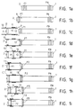
- Fig. 1a the plates P are shown clamped against each other, as they are during an operation of filtration.
- Fig. 1b they are just loose, the first plate P1 being retained by blocking means 9 to find at a determined distance from the moving head 2 when this is moved back to the end of its travel, Fig. 1 C.
- Fig. 1c is represented very schematic a device according to the invention, comprising a main carriage 10 moving on side rails of each side of the filter press, and carrying through a gantry crane, not shown, the stripping means, also not shown. On the main carriage 10, two carriages side 11 have a longitudinal displacement ability.
- the Fig. 1c shows the device moved back above the moving head 2, and the P1 plate unlocked
- the main carriage 10 has advanced and has positioned relative to the movable head 2 by means of reference point means 12. It is then locked in position, and in turn, it retains the P2 plate via the means 13 which it comprises in its front part.
- the secondary carriages 11 then move towards the front, to come and grab the P1 tray with their means of grip 14. They position the plate P1 in a position precise.
- the distance between the plate P1 and the movable head 2 is so at a precise dimension, just as they are perfectly positioned in relation to the stripping means which can get into action in a way that will be described later.
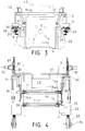
- the main carriage 10 has two platforms longitudinal 20 connected by crosspieces such as 21.
- Each platform 20 has front and rear rollers 22 bearing on the raceway 24 of a rail 23 mounted on the side of the frame 25 of the filter press.
- Centering rollers 26 with axes vertical roll on the inner side of the raceways 24, which comprise at their ends buffers 27.
- the movement of the main carriage 10 is ensured by a imprint chain and wheel drive system: two chains 28 run along the tracks 24, fixed at both ends. Each goes through a set of wheels with impressions 29 to 31 mounted on each side at the front of the carriage 10.
- the two wheels 30 are driven by motors 32, FIG. 4, operating synchronously.
- the carriage 10 is secured with a double locking assembly 33 - one brake system on each rail 23 - by means of jacks 34.
- the means 12 of the carriage 10 used for taking reference on the movable head 2, then on the trays stacked against it at measurement of the stripping, are visible in FIG. 4, where they did been shown only in the right hand side for clarity and better understanding of the drawing. They consist of two fingers, each mounted on the back of a platform 20 and controlled by a jack 35. At each advance of one step of the carriage 10, the fingers 12 come to engage in front of the ears 7 of the last Pn-1 tray stacked against the movable head 2. Of course, it also has ears like the trays, since the first reference point is taken in relation to it.
- the secondary carriages 11 used for handling the P plates are slidably mounted longitudinally on the platforms 20. They are controlled on the move by cylinders 36. As we saw previously with reference to FIGS. 1a to 1 hour, the carriages 11 include means for gripping tray with the mark 14. These means are made up on each carriage 11 of two independent fingers 14a, 14b, FIG. 4. Has for clarity and understanding, only finger 14a has been shown on the left side of Fig. 4.
- the fingers 14a are at the ends of the arms 37 articulated on the inside of the carts 11. Under their end adjacent to finger 14a, the arms 37 have a stud engaged in a groove 38 formed in the platforms 20, which groove is subdivided into a front oriented section longitudinally and a rear section obliquely towards outside. It is thus understood that in the advanced position of the carriages 11, the fingers 14a are engaged in the trajectory of the ears 7 of the plates, that they remain in this engagement position during the retraction of the carriages 11 to an intermediate position, and then they're retracted when the carriages 11 continue to retreat until limit switch.
- the fingers 14b are at the end of the arm 39 also articulated on the inside of the carriages 11 and pivotally controlled by jacks 40. In the engaged position, the fingers 14b are slightly in front of the fingers 14a and are separated by a distance slightly greater than the thickness of the ears 7 of the trays.
- the carriage 10 further comprises means 13 for retaining tray P of rank Pn + 1 when a tray P of rank n is manipulated by the means 14.
- the means 13 are shown in the Fig. 4. They are mounted on a front element of the carriage frame 10, here the crosspiece 21. These are legs 41 brought to the cylinder rod ends 42 which descend to engage behind the ears 7 of the trays.
- the fingers 12 are retracted, and the carriages 11 are in the retracted position. Therefore the fingers 14a are retracted, and the fingers 14b are also retracted retraction of the rods of the jacks 40. Similarly, the means 13, that is to say the pallets 41 in FIG. 3, are retracted towards the high.
- the carriage 10 is therefore free to move relative to to the plates P, and it can advance one step towards the fixed head, which step corresponds to the thickness of the plates.
- the fingers 12 are engaged in front of the ears of the Pn-1 plate, as illustrated in Fig. 4, and the carriages 11 are move forward, which has the effect of engaging the fingers 14a behind the ears of the platform Pn.
- the carts 11 progress to the end of the stroke, advancing possibly the Pn platform, also with the effect firmly apply fingers 12 against the ears of the Pn-1 plate.
- the brakes 33 come into action to block the carriage 10.
- the plates Pn-1 and Pn are thus firmly immobilized, precisely separated from each other at a so-called stripping, and precisely positioned in relation to the carriage 10, and therefore with respect to the cleaning means which will be described below, and which can therefore enter in action.
- the fingers 14b are engaged in front of the ears of the platform Pn and the legs 41 behind those of the Pn + 1 plate to retain it.
- the carts 11 back to bring the plate Pn towards the moving head.
- the fingers 14a retract and the plate Pn applies against the Pn-1 plate.
- the brakes 33 are then released, the fingers 14b and the legs 41 retracted, so that the carriage 10 can advance one not for a new cycle.
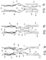
- the stripping means are visible in Figs. 2, 5, 6 and 7a to 7c. They are mounted on a gantry part properly said carried on the carriage 10, and which essentially comprises two uprights 50 joined by a transverse upper beam 51.
- raceways 52 with end damping stops stroke for a carriage 53.
- the carriage 53 is ordered uphill and downhill by means of endless chains 55 driven by imprint wheels 54.
- the two wheels 54 are connected to the same shaft 56 driven by a motor 57.
- the carriage 53 carries the stripping means, namely two arm systems 58 which, seen from the side in FIG. 6, are arranged in compass.
- Each arm 58 consists of two uprights 59, FIG. 5, joined by crosspieces 60.
- the uprights 59 are articulated each to the carriage 53. They are extended beyond the articulation upwards by branches 61 which are bent and deviate externally with respect to the transverse plane of symmetry of the compass mounting.
- the branches 61 carry at their end a roller 63 with transverse axis projecting from each side, as the shows fig. 5.
- transverse blades 62 At the base of the arms 58 are mounted transverse blades 62, of width slightly less than the internal width of the trays. They are fixed in a sandwich support to adjust the depth and their angle of attack: they are oriented obliquely to the arms 58, to be more open. In reality, their inclination is calculated to correspond substantially to that of the edges upper internal plates, as illustrated in Figs. 7a at 7c. On the other hand, the blades 62 are notched opposite the bosses 6 of the plates P.
- tracks also appear guide profiles for rollers 63 and 63 ', which control arms 58 in closing and opening, these being other part recalled during opening by springs, not shown, located at the joints of the uprights 59.
- devices have also been shown scraping blades 62 preventing the rise of material. he these are shutters 67 articulated on frame elements 68 and controlled by jacks 69. The flaps 67 are provided with a flap scraping the blades 62 during their ascent. Inside arms 58, product ascent is also prevented by a flexible plate 70, folded in a dihedral, joining the edges upper blades 62. The plate 70 is also used for retaining cakes during takeoff, to prevent them from break.
- the rollers 63 arrive on the divergent part guide tracks 66, so that the arms 58 move away from the being recalled when opening and that the blades are coming lean in force on ledges 3.
- the rollers 63 arrive in engagement on guide tracks 64.
- they are guided so that the blades 62 descend along the bottom 4 of the trays without leaning on them, or even very slightly set aside.
- the plate 70 the cake G is prevented from breaking in two during takeoff, as shown in Fig. 7b.
- rollers 63 have arrived on a second section of the guide tracks 64 with the effect to slightly close the arms 58, therefore to spread a little more the blades 62 of the bottom of the trays for passage over the central hole 5, where the folding of the filter cloth makes it more vulnerable.
- a third section of the guide tracks 64 in the extension of the first section, corresponds to passage of the blades 62 along the bottom of the bottom 4.
Abstract
Description
La présente invention concerne le débâtissage dans un filtre-presse, soit l'évacuation des gâteaux après qu'une opération de filtration a été effectuée.The present invention relates to the stripping in a filter press, i.e. the evacuation of cakes after a filtration operation was performed.
Dans un filtre-presse, les plateaux sont suspendus par des oreilles latérales sur deux glissières entre une tête fixe et une tête mobile. Ils sont serrés les uns contre les autres en une pile horizontale lors de la filtration et, pour l'évacuation des gâteaux, ils sont écartés tour à tour de la pile, vers la tête mobile.In a filter press, the trays are suspended by lateral ears on two slides between a fixed head and a moving head. They are pressed against each other in one horizontal stack during filtration and, for the evacuation of cakes, they are pushed away from the stack, towards the head mobile.
Généralement, cette manipulation des plateaux est réalisée de façon automatique au moyen d'un dipositif tel que décrit dans le brevet français FR-A-2 382 917 au nom de la S.A. des Fonderies et Ateliers L. Choquenet. Ce dispositif comprend, de chaque côté des plateaux, un chariot dit de halage fonctionnant en combinaison avec un chariot de blocage. Celui-ci a pour fonction de retenir le deuxième plateau dans la pile, tandis que le premier plateau est saisi par le chariot de halage et écarté vers la tête mobile, contre laquelle une pile de plateaux vides est reformée.Generally, this manipulation of the trays is carried out automatically by means of a device as described in French patent FR-A-2 382 917 in the name of S.A. des Fonderies and Ateliers L. Choquenet. This device includes, on each side trays, a so-called hauling cart operating in combination with a blocking carriage. Its function is retain the second tray in the stack, while the first platform is gripped by the towing cart and moved towards the movable head, against which a stack of empty trays is reformed.
Dans le principe, les gâteaux sont censés tomber lors de cette manoeuvre, mais si les produits traités sont colmatants, leur décollage doit être effectué par des opérateurs se trouvant de chaque côté du filtre-presse et disposant d'une rame en bois qu'ils viennent insérer entre le gâteau et la toile filtrante du plateau. Il s'agit là d'une tâche répétitive pénible, et qui soumet la toile filtrante à des chocs qui en accélèrent l'usure.In principle, the cakes are supposed to fall when this maneuver, but if the products treated are clogging, their take-off must be carried out by operators who are on each side of the filter press and having a wooden oar they insert between the cake and the filter cloth of the tray. This is a tedious repetitive task, and one that subjects the filter cloth to shocks which accelerate wear.
On connaít par le brevet DE-B-1302541 au nom de E. Hoesch & Söhne, un filtre-presse pourvu d'un dispositif pour évacuer les gâteaux. Pour le débâtissage, chaque plateau de la pile est écarté tour à tour, deux lames, guidées par des pistons, descendent entre le gâteau et la toile filtrante, et puis elles remontent, en appuyant toujours pendant leur mouvement sur la toile. Il s'agit là d'un système qui accélère l'usure des toiles filtrantes. We know by patent DE-B-1302541 in the name of E. Hoesch & Söhne, a filter press with a device for evacuating cakes. For de-beating, each stack tray is spread in turn, two blades, guided by pistons, go down between the cake and the filter cloth, and then they go up, always pressing for their movement on the canvas. This is a system which accelerates the wear of the filter cloths.
On connaít aussi par le brevet FR-A-2 452 951 au nom de Ishigaki Kiko Co., Ltd, un filtre-presse pourvu d'un dispositif pour évacuer les gâteaux. Le dispositif agit par vibrations et, pour ce faire, les plateaux sont de conception spéciale : l'extrémité inférieure de la toile est fixée sur le bord inférieur du plateau, tandis que son extrémité supérieure est engagée sur un support susceptible de monter et descendre par rapport au haut du plateau, et contraint vers le haut par des ressorts. Pour le débâtissage, chaque plateau est écarté tour à tour de la pile, puis ledit support est soumis à des vibrations qui, transmises à la toile, ont pour effet de détacher le gâteau. Les moyens pour écarter les plateaux de la pile et les moyens générateurs de vibration sont montés sur un portique porté par deux chariots mobiles de chaque côté du filtre-presse. Un inconvénient de ce système est qu'il nécessite des plateaux spécifiques de structure complexe.We also know by patent FR-A-2 452 951 in the name of Ishigaki Kiko Co., Ltd, a filter press with a device for remove the cakes. The device acts by vibration and, for do this, the trays are of special design: the end bottom of the canvas is attached to the bottom edge of the tray, while its upper end is engaged on a support likely to go up and down from the top of the plate, and constrained upwards by springs. For the stripping, each plate is removed in turn from the pile, then said support is subjected to vibrations which, transmitted to the canvas, have the effect of detaching the cake. The means for move aside the battery trays and the means generating vibration are mounted on a gantry carried by two trolleys mobile on each side of the filter press. One drawback of this system is that it requires specific structure trays complex.
L'invention a pour objet principal de prévoir un dispositif de débâtissage automatique pour des filtres-presses comprenant des plateaux classiques.The main object of the invention is to provide a device of automatic cleaning for filter presses comprising classic trays.
Elle a également pour objet que le débâtissage soit réalisé sans fatigue pour la toile filtrante des plateaux.It also has as its object that the degreasing be carried out without fatigue for the filter cloth of the trays.
A cet effet, dans un filtre-presse comportant des plateaux
suspendus par des oreilles latérales sur des glissières entre une
tête fixe et une tête mobile, lesquels plateaux, de rang 1 à N à
partir de la tête mobile, sont recouverts d'une toile filtrante,
un dispositif selon l'invention est caractérisé en ce qu'il
comprend en combinaison sur un portique transversal apte à se
déplacer longitudinalement au-dessus des plateaux, des moyens de
débâtissage et des moyens de manipulation de-plateaux pour saisir
tour à tour chaque plateau de rang n, le positionner en une
position dite de débâtissage à une distance prédéterminée du
plateau précédent de rang n-1, et l'amener contre celui-ci après
l'opération de débâtissage, ledit portique comprenant en outre
des moyens pour se positionner relativement au plateau de rang
n-1,
D'autres caractéristiques et avantages de l'invention
apparaítront à la lecture de la description suivante, faite en
relation avec les dessins annexés, dans lesquels :
Dans l'ensemble des dessins, les mêmes signes de référence ont été affectés partout aux mêmes éléments.Throughout the drawings, the same reference signs were assigned everywhere to the same elements.
Dans le filtre-presse représenté schématiquement aux
Figs. 1a à 1i, une suite de plateaux P1 à PN est placée sur des
glissières entre une tête fixe 1 et une tête mobile 2. Les
plateaux P sont de conception classique, fabriqués en
polypropylène ou autre matière synthétique. Leur pourtour est un
cadre 3 formant saillie autour de leur paroi 4, comme on peut le
voir aux Figs. 3, 5 et 7. Ils présentent un trou central 5 pour
le remplissage et, autour de ce trou, quatre bossages 6 de même
épaisseur que le cadre 3, prévus pour éviter leur déformation.
Ils sont recouverts des deux côtés d'une toile filtrante. Des
oreilles latérales 7 les maintiennent suspendus sur des
glissières 8 entre les têtes 1 et 2.In the filter press shown schematically in
Figs. 1a to 1i, a series of plates P1 to PN is placed on
slides between a
A la Fig. 1a, les plateaux P sont représentés serrés les
uns contre les autres, tels qu'ils sont lors d'une opération de
filtration. A la Fig. 1b, ils sont juste desserrés, le premier
plateau P1 étant retenu par des moyens de blocage 9 pour se
trouver à une distance déterminée de la tête mobile 2 lorsque
celle-ci est reculée en bout de course, Fig. 1c.In Fig. 1a, the plates P are shown clamped
against each other, as they are during an operation of
filtration. In Fig. 1b, they are just loose, the first
plate P1 being retained by blocking means 9 to
find at a determined distance from the moving
A partir de la Fig. 1c, est représenté de façon très
schématique un dispositif conforme à l'invention, comportant un
chariot principal 10 se déplaçant sur des glissières latérales de
chaque côté du filtre-presse, et portant par l'intermédiaire d'un
portique, non représenté, les moyens de débâtissage, également
non représentés. Sur le chariot principal 10, deux chariots
latéraux 11 ont une aptitude de déplacement longitudinal. La
Fig. 1c montre le dispositif reculé au-dessus de la tête mobile
2, et le plateau P1 débloquéFrom Fig. 1c, is represented very
schematic a device according to the invention, comprising a
A la Fig. 1d, le chariot principal 10 a avancé et s'est
positionné par rapport à la tête mobile 2 par l'intermédiaire de
moyens de prise de référence 12. Il est alors bloqué en position,
et à son tour, il retient le plateau P2 par l'intermédiaire des
moyens 13 qu'il comporte dans sa partie avant.In Fig. 1d, the
Les chariots secondaires 11 se déplacent alors vers
l'avant, pour venir saisir le plateau P1 avec leurs moyens de
préhension 14. Ils positionnent le plateau P1 dans une position
précise. L'écartement entre le plateau P1 et la tête mobile 2 est
donc à une cote précise, de même qu'ils sont parfaitement
positionnés par rapport aux moyens de débâtissage qui peuvent
entrer en action d'une manière qui sera décrite dans la suite.The
Une fois le débâtissage effectué entre la tête mobile 2 et
le plateau P1, ce dernier toujours tenu par les chariots
secondaires 11 est amené par eux contre la tête mobile 2,
Fig. 1f, tandis que le plateau P2 est libéré par les moyens 13.Once the cleaning has been carried out between the
Le chariot principal 10 est alors débloqué puis avance d'un
pas pour se positionner maintenant par rapport au plateau P1,
Fig. 1g. Les états 1h et 1i sont les équivalents des états 1e et
1f pour le plateau P2. Les cycles sont répétés jusqu'au dernier
plateau PN.The
Les moyens de manipulation des plateaux P dont le
fonctionnement vient d'être décrit apparaissent aux Figs. 2 à 4.
Le chariot principal 10 présente deux plates-formes
longitudinales 20 reliées par des traverses telles que 21. Chaque
plate-forme 20 comporte des galets avant et arrière 22 portant
sur le chemin de roulement 24 d'un rail 23 monté sur le côté du
bâti 25 du filtre-presse. Des galets de centrage 26 à axes
verticaux roulent sur le côté intérieur des chemins de roulement
24, lesquels comportent à leurs extrémités des butoirs 27.The means of handling the trays P including the
operation has just been described appear in Figs. 2 to 4.
The
Le déplacement du chariot principal 10 est assuré par un
système d'entraínement à chaíne et à roues à empreintes : deux
chaínes 28 courent le long des chemins de roulement 24, fixées
aux deux extrémités. Chacune passe dans un ensemble de roues à
empreintes 29 à 31 monté de chaque côté à l'avant du chariot 10.
Les deux roues 30 sont entraínées par des moteurs 32, Fig. 4,
fonctionnant de façon synchrone.The movement of the
A l'arrière, le chariot 10 est solidarisé avec un double
ensemble de blocage 33 - un système de frein sur chaque rail
23 - par l'intermédiaire de vérins 34.At the rear, the
Les moyens 12 du chariot 10 servant à la prise de référence
sur la tête mobile 2, puis sur les plateaux empilés contre elle à
mesure du débâtissage, sont visibles à la Fig. 4, où ils n'ont
été représentés que dans la partie droite à des fins de clarté et
de meilleure compréhension du dessin. Ils consistent en deux
doigts, montés chacun à l'arrière d'une plate-forme 20 et
commandé par un vérin 35. A chaque avance d'un pas du chariot 10,
les doigts 12 viennent s'engager devant les oreilles 7 du dernier
plateau Pn-1 empilé contre la tête mobile 2. Bien entendu, elle
aussi comporte des oreilles comme les plateaux, puisque la
première prise de référence est réalisée par rapport à elle.The means 12 of the
Les chariots secondaires 11 servant à la manipulation des
plateaux P sont montés coulissants longitudinalement sur les
plates-formes 20. Ils sont commandés en déplacement par des
vérins 36. Comme on l'a vu précédemment à propos des Figs. 1a à
1h, les chariots 11 comportent des moyens de préhension de
plateau portant le repère 14. Ces moyens se composent sur chaque
chariot 11 de deux doigts indépendants 14a, 14b, Fig. 4. A des
fins de clarté et de compréhension, seul le doigt 14a a été
représenté dans la partie gauche de la Fig. 4.The
Les doigts 14a se trouvent à l'extrémités de bras 37
articulés sur le côté intérieur des chariots 11. Sous leur
extrémité adjacente au doigt 14a, les bras 37 comportent un téton
engagé dans une gorge 38 ménagée dans les plates-formes 20,
laquelle gorge se subdivise en un tronçon avant orienté
longitudinalement et un tronçon arrière obliquant vers
l'extérieur. On comprend ainsi qu'en position avancée des
chariots 11, les doigts 14a se trouvent engagés dans la
trajectoire des oreilles 7 des plateaux, qu'ils demeurent dans
cette position d'engagement lors du recul des chariots 11
jusqu'en une position intermédiaire, et qu'ils sont ensuite
escamotés lorsque les chariots 11 continuent de reculer jusqu'en
fin de course.The fingers 14a are at the ends of the
Les doigts 14b se trouvent à l'extrémité de bras 39
également articulés sur le côté intérieur des chariots 11 et
commandés en pivotement par des vérins 40. En position engagée,
les doigts 14b sont légèrement devant les doigts 14a et en sont
écartés d'une distance légèrement supérieure à l'épaisseur des
oreilles 7 des plateaux. The fingers 14b are at the end of the
Le chariot 10 comporte en outre des moyens 13 pour retenir
le plateau P de rang Pn+1 lorsqu'un plateau P de rang n est
manipulé par les moyens 14. Les moyens 13 sont représentés à la
Fig. 4. Ils sont montés sur un élément avant du bâti du chariot
10, ici la traverse 21. Ce sont des pattes 41 portées aux
extrémités de tiges de vérins 42 qui descendent pour s'engager
derrière les oreilles 7 des plateaux.The
En fonctionnement, une fois q'un plateau Pn-1 a été rempilé
du côté de la tête mobile, les doigts 12 sont escamotés, et les
chariots 11 sont en position reculée. Par conséquent les doigts
14a sont escamotés, et les doigts 14b le sont également par
rentrée des tiges des vérins 40. De même, les moyens 13,
c'est-à-dire les palettes 41 à la Fig. 3, sont escamotées vers le
haut. Le chariot 10 est donc libre de tout mouvement par rapport
aux plateaux P, et il peut avancer d'un pas vers la tête fixe,
lequel pas correspond à l'épaisseur des plateaux.In operation, once a Pn-1 tray has been re-stacked
on the side of the movable head, the
Ensuite, les doigts 12 sont engagés devant les oreilles du
plateau Pn-1, comme illustré à la Fig. 4, et les chariots 11 se
déplacent vers l'avant, ce qui a pour effet d'engager les doigts
14a derrière les oreilles du plateau Pn. Les chariots 11
progressent jusqu'en bout de course, en faisant avancer
éventuellement le plateau Pn, avec également pour effet
d'appliquer fermement les doigts 12 contre les oreilles du
plateau Pn-1. Alors, les freins 33 entrent en action pour bloquer
le chariot 10.Then, the
Les plateaux Pn-1 et Pn sont ainsi fermement immobilisés,
précisément écartés l'un de l'autre à une cote dite de
débâtissage, et précisément positionnés par rapport au chariot
10, et par conséquent par rapport aux moyens de débâtissage qui
vont être décrits dans la suite, et qui peuvent dès lors entrer
en action.The plates Pn-1 and Pn are thus firmly immobilized,
precisely separated from each other at a so-called
stripping, and precisely positioned in relation to the
Une fois que ceux-ci ont fini d'opérer, les doigts 14b sont
engagés devant les oreilles du plateau Pn et les pattes 41
derrière celles du plateau Pn+1 pour le retenir. Les chariots 11
reculent pour amener le plateau Pn vers la tête mobile. En fin de
course de recul, les doigts 14a s'escamotent et le plateau Pn
s'applique contre le plateau Pn-1.Once these have finished operating, the fingers 14b are
engaged in front of the ears of the platform Pn and the
Les freins 33 sont alors desserrés, les doigts 14b et les
pattes 41 escamotés, de sorte que le chariot 10 peut avancer d'un
pas pour un nouveau cycle.The
Il est bien évident que si un plateau P est défectueux, il
faut profiter pour le changer de son transfert de la pile contre
la tête fixe à la pile contre la tête mobile. Or, ce transfert
s'accomplit sous les moyens de débâtissage qui interdisent donc
d'extraire le plateau par le haut. C'est pourquoi il est prévu,
selon l'invention, une liaison par vérins entre le chariot 10 et
les freins 33. En cas de besoin, les vérins 34 sont déployés pour
dégager le plateau à changer, les freins 33 étant serrés. Lorsque
les vérins 34 sont rétractés, le chariot 10 reprend exactement sa
position antérieure, si bien que le débâtissage peut se
poursuivre.It is obvious that if a P tray is defective, it
must take advantage to change it from its transfer from the stack against
the head fixed to the pile against the movable head. Now, this transfer
is accomplished under the means of defatting which therefore prohibit
extract the tray from above. That’s why it’s planned,
according to the invention, a connection by jacks between the
Les moyens électriques, automate, et centrale hydraulique
commandant les différents mouvements sont embarqués sur le
chariot 10. Ils portent la référence 43 aux Figs. 2 à 4.Electrical means, automaton, and hydraulic power station
commanding the various movements are embarked on the
Les moyens de débâtissage sont visibles aux Figs. 2, 5, 6
et 7a à 7c. Ils sont montés sur une partie portique proprement
dite portée sur le chariot 10, et qui comprend essentiellement
deux montants 50 réunis par une poutre supérieure transversale
51.The stripping means are visible in Figs. 2, 5, 6
and 7a to 7c. They are mounted on a gantry part properly
said carried on the
Le long des côtés intérieurs des montants 50, sont ménagés
des chemins de roulement 52 avec butées d'amortissement de fin de
course pour un chariot 53. Le chariot 53 est commandé en montée
et en descente au moyen de chaínes sans fin 55 entraínées par des
roues à empreinte 54. Les deux roues 54 sont reliées à un même
arbre 56 entraíné par un moteur 57.Along the interior sides of the
Le chariot 53 porte les moyens de débâtissage, à savoir
deux systèmes de bras 58 qui, vus de côté à la Fig. 6, sont
disposés en compas. The
Chaque bras 58 est constitué de deux montants 59, Fig. 5,
réunis par des traverses 60. Les montants 59 sont articulés
chacun au chariot 53. Il sont prolongés au-delà de l'articulation
vers le haut par des branches 61 qui sont coudées et s'écartent
extérieurement par rapport au plan de symétrie transversal du
montage en compas. Les branches 61 portent à leur extrémité un
rouleau 63 d'axe transversal dépassant de chaque côté, comme le
montre la Fig. 5. Des rouleaux identiques 63' sont prévus sur les
montants 59, à distance de leur extrémité inférieure, et sur leur
face extérieure, toujours en se référant au montage en compas.Each
A la base des bras 58, sont montées des lames transversales
62, de largeur légèrement inférieure à la largeur intérieure des
plateaux. Elles sont fixées dans un support en sandwich
permettant de régler la profondeur et leur angle d'attaque :
elles sont orientées obliquement par rapport aux bras 58, de
façon à être plus ouvertes. En réalité, leur inclinaison est
calculée de manière à correspondre sensiblement à celle des bords
internes supérieurs des plateaux, comme l'illustrent les Figs. 7a
à 7c. D'autre part, les lames 62 sont échancrées en face des
bossages 6 des plateaux P.At the base of the
Aux Figs. 7a à 7c, apparaissent également des pistes
profilées de guidage pour les rouleaux 63 et 63', qui commandent
les bras 58 en fermeture et en ouverture, ceux-ci étant d'autre
part rappelés en ouverture par des ressorts, non montrés, se
trouvant au niveau des articulations des montants 59. Il y a deux
pistes de guidage 64 et 65 pour chaque rouleau 63, l'une affectée
à la descente, et l'autre à la montée, et une piste de guidage 66
pour chaque rouleau 63'. Ces pistes de guidage vont être décrites
plus en détail dans la suite, lors de l'explication du
fonctionnement.In Figs. 7a to 7c, tracks also appear
guide profiles for
A la Fig. 6, ont en outre été représentés des dispositifs
de râclage des lames 62 empêchant la remontée de matière. Il
s'agit de volets 67 articulés sur des éléments de bâti 68 et
commandés par des vérins 69. Les volets 67 sont pourvus d'une
bavette râclant les lames 62 lors de leur remontée. A l'intérieur
des bras 58, la remontée de produit est également empêchée par
une plaque flexible 70, repliée en dièdre, réunissant les bords
supérieurs des lames 62. La plaque 70 sert de plus à la retenue
des gâteaux lors du décollage, pour empêcher qu'ils ne se
cassent.In Fig. 6, devices have also been shown
scraping
On va maintenant décrire le fonctionnement du système de
débâtissage en se référant aux Figs. 6 et 7a à 7c. A la Fig. 6,
les bras 58 sont en position haute. Ils sont retenus en fermeture
par appui des rouleaux 63' sur les pistes de guidage 66. Les
rouleaux 63 sont au-dessus des pistes de guidage 64.We will now describe the functioning of the
stripping with reference to Figs. 6 and 7a to 7c. In Fig. 6,
the
Au début d'un cycle de débâtissage, lorsque s'amorce le
mouvement de descente, les bras 58 restent maintenus en fermeture
par les rouleaux 63' sur les pistes de guidage 66 jusqu'à ce que
les lames 62 pénètrent dans l'espace entre les rebords supérieurs
3 des plateaux Pn-1 et Pn en position de débâtissage.At the start of a degreasing cycle, when the
lowering movement,
Alors, les rouleaux 63' arrivent sur la partie divergente
des pistes de guidage 66, de sorte que les bras 58 s'écartent du
fait d'être rappelés en ouverture et que les lames viennent
s'appuyer en force sur les rebords 3. Quand elles arrivent au
niveau du bord interne 3a des plateaux P, elles s'insèrent donc
entre celui-ci et le haut du gâteau G, comme l'illustre la
Fig. 7a. Dans le même temps, les rouleaux 63 arrivent en
engagement sur les pistes de guidage 64. Dans une première phase,
ils sont guidés de manière que les lames 62 descendent le long du
fond 4 des plateaux sans s'y appuyer, ou même très légèrement
écartées. Par la plaque 70, le gâteau G est empêché de se casser
en deux en cours de décollage, comme l'illustre la Fig. 7b. On
voit également sur cette figure que les rouleaux 63 sont arrivés
sur une deuxième section des pistes de guidage 64 avec pour effet
de refermer légèrement les bras 58, donc d'écarter un peu plus
les lames 62 du fond des plateaux pour le passage au-dessus du
trou central 5, où le repli de la toile filtrante la rend plus
vulnérable. Ensuite, une troisième section des pistes de guidage
64, dans le prolongement de la première section, correspond au
passage des lames 62 le long de la partie inférieure du fond 4.Then, the rollers 63 'arrive on the divergent part
guide tracks 66, so that the
Quand les lames 62 arrivent à proximité du bord inférieur
3a des plateaux, le gâteau est complètement décollé et évacué, et
les bras 58 se referment, les rouleaux 63 passant sur une
quatrième section divergente des pistes de guidage 64. Ils
passent alors de l'autre côté de volets 72 n'autorisant qu'un
sens de passage et qui les aiguillent sur les pistes de guidage
65, Fig. 7. Lors du mouvement de remontée, les bras 58 sont ainsi
maintenus fermés, les lames 62 étant à distance des plateaux Pn-1
et Pn. En fin de remontée, les rouleaux 63 quittent les pistes de
guidage 65. Les bras 58 s'ouvrent légèrement mais sont à nouveau
retenus par les rouleaux 63' reprenant appui contre le haut des
pistes de guidage 66. Cette légère ouverture des bras 58 est
nécessaire pour refaire passer les rouleaux 63 du côté des pistes
de guidage 64.When the
Claims (11)
- A dismantling device for a filter press comprising plates (P1 to PN) suspended by lateral lugs (2) on slide bars (8) between a fixed head (1) and a mobile head (2), said plates, arranged in order from 1 to N starting from the mobile head (2), being covered by a filter cloth, having in addition in combination on a transverse gantry (10, 50, 51) designed to be displaced longitudinally above the plates, dismantling means and means for handling the plates in order to pick up each plate of rank n in turn, position it in what is referred to as a dismantling position at a predetermined distance from the preceding plate of rank n-1 and bring it to bear on this latter after the dismantling operation, said gantry also having means for positioning itself relative to the plate of rank n-1,the dismantling means having a vertically displaceable carriage (53) and, symmetrically arranged as a compass relative to a transverse plane, two arms (58) articulated about transverse axes on this carriage (53), each bearing at its bottom end a transverse blade (62) obliquely oriented relative to these in the direction of opening, the two arms (58) being resiliently loaded for opening and being guided during opening/closing depending on the lowering and lifting movements of the carriage (53),so that during operation, when said carriage (53) is being lowered, the blades (62) engage between flanges (3) of the two plates in the dismantling position, are applied thereto by the return force during opening so as to be inserted between inner top edges (3a) of the plates and the height of the cakes (G), are then lowered along the base of the plates without bearing on the cloth and are folded back during closing so as to pass the lower flanges of the plates; and when the carriage (53) is being lifted, the blades (62) remain in the folded-back closing position so as to pass between the plates.
- A device as claimed in claim 1, characterised in that the guiding means for opening/closing the arms (58) of the dismantling means are profiled tracks (64 to 66) against which rollers integral with the arms (58) bear.
- A device as claimed in claim 1 or 2, characterised in that the blades (62) are mounted at the ends of the arms (58) in sandwich supports so that the depth and angle of attack thereof can be adjusted.
- A device as claimed in one of claims 1 to 3, characterised in that means for scraping (67) the blades (62) are provided to avoid product being lifted back up.
- A device as claimed in one of claims 1 to 4, characterised in that the top edges of the blades (62) are joined by a flexible plate (70) folded back in a dihedral.
- A device as claimed in one of claims 1 to 5, characterised in that said gantry (10, 50, 51) has, fixed onto a carriage (10), two lateral uprights (50) and a cross-beam (51) bearing the dismantling means and the carriage (10) has two lateral platforms (20) which can be moved longitudinally on tracks (23), said platforms being joined by cross-pieces (21) and bearing said plate handling means.
- A device as claimed in claim 6, characterised in that the platforms (20) have, at the front, means for providing drive on the tracks (23) and, at the rear, means to provide locking (33) on the same tracks (23).
- A device as claimed in claim 7, characterised in that the platforms (20) are joined to locking means (33) by jacks (34) so that they can be displaced in longitudinal translation relative to these locking means (33).
- A device as claimed in one of claims 6 to 8, characterised in that said plate-handling means are foldable fingers (14a, 14b) mounted on secondary carriages (11) which move longitudinally on platforms (20).
- A device as claimed in one of claims 6 to 9, characterised in that said means for positioning the gantry (10, 50, 51) relative to a plate previously stacked against the mobile head (2) are foldable fingers (12) mounted in the rear part of the platforms (20).
- A device as claimed in one of claims 6 to 10, characterised in that the means for handling the plate (Pn) are associated with means for retaining (13) the subsequent plate (Pn+1), said retaining means (13) being mounted at the front of the platforms (20).
Applications Claiming Priority (2)
| Application Number | Priority Date | Filing Date | Title |
|---|---|---|---|
| FR9301136 | 1993-01-28 | ||
| FR9301136A FR2700711B1 (en) | 1993-01-28 | 1993-01-28 | Automatic stripping device for filter press. |
Publications (2)
| Publication Number | Publication Date |
|---|---|
| EP0609164A1 EP0609164A1 (en) | 1994-08-03 |
| EP0609164B1 true EP0609164B1 (en) | 1998-07-29 |
Family
ID=9443657
Family Applications (1)
| Application Number | Title | Priority Date | Filing Date |
|---|---|---|---|
| EP94460002A Expired - Lifetime EP0609164B1 (en) | 1993-01-28 | 1994-01-26 | Automatic filter press plate separating device |
Country Status (4)
| Country | Link |
|---|---|
| EP (1) | EP0609164B1 (en) |
| AT (1) | ATE168899T1 (en) |
| DE (1) | DE69411960D1 (en) |
| FR (1) | FR2700711B1 (en) |
Families Citing this family (1)
| Publication number | Priority date | Publication date | Assignee | Title |
|---|---|---|---|---|
| BE1017346A3 (en) * | 2006-10-27 | 2008-06-03 | Welders Filtration Technology | DEVICE FOR SCRAPTING THE FILTER COWS OF A FILTER PRESS. |
Family Cites Families (2)
| Publication number | Priority date | Publication date | Assignee | Title |
|---|---|---|---|---|
| DE1302541B (en) * | 1961-03-25 | 1972-05-31 | ||
| DE3007404A1 (en) * | 1979-04-05 | 1980-10-23 | Ishigaki Mech Ind | DEVICE FOR REMOVING THE FILTER CAKE FROM A FILTER PRESS |
-
1993
- 1993-01-28 FR FR9301136A patent/FR2700711B1/en not_active Expired - Fee Related
-
1994
- 1994-01-26 EP EP94460002A patent/EP0609164B1/en not_active Expired - Lifetime
- 1994-01-26 DE DE69411960T patent/DE69411960D1/en not_active Expired - Lifetime
- 1994-01-26 AT AT94460002T patent/ATE168899T1/en not_active IP Right Cessation
Also Published As
| Publication number | Publication date |
|---|---|
| ATE168899T1 (en) | 1998-08-15 |
| FR2700711B1 (en) | 1995-03-31 |
| DE69411960D1 (en) | 1998-09-03 |
| FR2700711A1 (en) | 1994-07-29 |
| EP0609164A1 (en) | 1994-08-03 |
Similar Documents
| Publication | Publication Date | Title |
|---|---|---|
| FR2683515A1 (en) | Apparatus for gripping and transporting stacks of flat objects | |
| EP0354873A1 (en) | Depalletizer for parcels of labels | |
| FR2509271A1 (en) | STORAGE AND STORAGE WITHDRAWAL MECHANISM FOR USE WITH AN AUTOMATED AND ROTATING STORAGE UNIT | |
| EP0248700B1 (en) | Packaging machine for "american" boxes | |
| EP0029384A1 (en) | Lift truck with synchronised adjustement of variable rolling and gripping surfaces | |
| FR2470744A1 (en) | DEVICE FOR LOADING GOODS IN PARCELS ON PALLETS | |
| CH373688A (en) | Method for inserting a collapsible partition blank between rows of containers to be packaged and a machine for carrying out this method | |
| EP0543711B1 (en) | Bridge element, especially for surmounting gaps by vehicles | |
| EP0609164B1 (en) | Automatic filter press plate separating device | |
| WO2008093030A2 (en) | Device for storing objects on a mobile pallet | |
| EP0219520B1 (en) | Truck for transferring plates, particularly for freeze-drying, and corresponding loading/unloading installation | |
| CH663780A5 (en) | DYNAMIC STORAGE FACILITY, ESPECIALLY FOR FRAGILE PRODUCTS SUCH AS CHEESES. | |
| FR2602119A1 (en) | Automatic machine for loading and unloading trays of shelf frames in the treatment of meats in general | |
| FR2668895A1 (en) | MACHINE FOR THE PREPARATION OF SKEWERS. | |
| FR2639611A1 (en) | Device for placing a cover over a load packaged by means of hoop-casing | |
| EP0255448B1 (en) | Device for handling crates, especially crates with a mobile bottom to handle goods at a constant level | |
| EP0040571B1 (en) | Stacking device for stacking articles circulating one after the other along a conveyor | |
| FR2524441A3 (en) | Inserting layer sepg. sheet when loading can steriliser cage - by horizontally advancing bottom sheet from gravity feed magazine stack | |
| WO2016001556A1 (en) | Module for placing sleeves | |
| EP0209480B1 (en) | Partition element, especially for a cardboard box, and machine for the automatic shaping and inserting of this device | |
| FR2629809A1 (en) | APPARATUS FOR HANDLING CONTAINERS SUCH AS FOR EXAMPLE BAGS | |
| FR2537120A1 (en) | Container self-aligning device for a handling trolley. | |
| FR2530201A1 (en) | Apparatus for the automatic loading of the total volume of a transport vehicle. | |
| FR2545383A1 (en) | Automatic machine for the spray painting and drying of flat articles, and especially of wooden panels | |
| FR2625946A1 (en) | INSTALLATION FOR MANUFACTURING AND STACKING BAGS, BAGS, ETC. IN THERMOPLASTIC MATTER |
Legal Events
| Date | Code | Title | Description |
|---|---|---|---|
| PUAI | Public reference made under article 153(3) epc to a published international application that has entered the european phase |
Free format text: ORIGINAL CODE: 0009012 |
|
| AK | Designated contracting states |
Kind code of ref document: A1 Designated state(s): AT BE DE ES GB IT NL PT SE |
|
| 17P | Request for examination filed |
Effective date: 19941003 |
|
| RAP3 | Party data changed (applicant data changed or rights of an application transferred) |
Owner name: KAOLINS D'ARVOR SA |
|
| GRAG | Despatch of communication of intention to grant |
Free format text: ORIGINAL CODE: EPIDOS AGRA |
|
| 17Q | First examination report despatched |
Effective date: 19971013 |
|
| GRAG | Despatch of communication of intention to grant |
Free format text: ORIGINAL CODE: EPIDOS AGRA |
|
| GRAH | Despatch of communication of intention to grant a patent |
Free format text: ORIGINAL CODE: EPIDOS IGRA |
|
| GRAH | Despatch of communication of intention to grant a patent |
Free format text: ORIGINAL CODE: EPIDOS IGRA |
|
| GRAA | (expected) grant |
Free format text: ORIGINAL CODE: 0009210 |
|
| AK | Designated contracting states |
Kind code of ref document: B1 Designated state(s): AT BE DE ES GB IT NL PT SE |
|
| PG25 | Lapsed in a contracting state [announced via postgrant information from national office to epo] |
Ref country code: NL Free format text: LAPSE BECAUSE OF FAILURE TO SUBMIT A TRANSLATION OF THE DESCRIPTION OR TO PAY THE FEE WITHIN THE PRESCRIBED TIME-LIMIT Effective date: 19980729 Ref country code: IT Free format text: LAPSE BECAUSE OF FAILURE TO SUBMIT A TRANSLATION OF THE DESCRIPTION OR TO PAY THE FEE WITHIN THE PRESCRIBED TIME-LIMIT;WARNING: LAPSES OF ITALIAN PATENTS WITH EFFECTIVE DATE BEFORE 2007 MAY HAVE OCCURRED AT ANY TIME BEFORE 2007. THE CORRECT EFFECTIVE DATE MAY BE DIFFERENT FROM THE ONE RECORDED. Effective date: 19980729 Ref country code: GB Free format text: LAPSE BECAUSE OF FAILURE TO SUBMIT A TRANSLATION OF THE DESCRIPTION OR TO PAY THE FEE WITHIN THE PRESCRIBED TIME-LIMIT Effective date: 19980729 Ref country code: ES Free format text: THE PATENT HAS BEEN ANNULLED BY A DECISION OF A NATIONAL AUTHORITY Effective date: 19980729 Ref country code: AT Free format text: LAPSE BECAUSE OF FAILURE TO SUBMIT A TRANSLATION OF THE DESCRIPTION OR TO PAY THE FEE WITHIN THE PRESCRIBED TIME-LIMIT Effective date: 19980729 |
|
| REF | Corresponds to: |
Ref document number: 168899 Country of ref document: AT Date of ref document: 19980815 Kind code of ref document: T |
|
| REF | Corresponds to: |
Ref document number: 69411960 Country of ref document: DE Date of ref document: 19980903 |
|
| PG25 | Lapsed in a contracting state [announced via postgrant information from national office to epo] |
Ref country code: SE Free format text: LAPSE BECAUSE OF FAILURE TO SUBMIT A TRANSLATION OF THE DESCRIPTION OR TO PAY THE FEE WITHIN THE PRESCRIBED TIME-LIMIT Effective date: 19981029 Ref country code: PT Free format text: LAPSE BECAUSE OF FAILURE TO SUBMIT A TRANSLATION OF THE DESCRIPTION OR TO PAY THE FEE WITHIN THE PRESCRIBED TIME-LIMIT Effective date: 19981029 |
|
| PG25 | Lapsed in a contracting state [announced via postgrant information from national office to epo] |
Ref country code: DE Free format text: LAPSE BECAUSE OF FAILURE TO SUBMIT A TRANSLATION OF THE DESCRIPTION OR TO PAY THE FEE WITHIN THE PRESCRIBED TIME-LIMIT Effective date: 19981030 |
|
| NLV1 | Nl: lapsed or annulled due to failure to fulfill the requirements of art. 29p and 29m of the patents act | ||
| GBV | Gb: ep patent (uk) treated as always having been void in accordance with gb section 77(7)/1977 [no translation filed] |
Effective date: 19980729 |
|
| PG25 | Lapsed in a contracting state [announced via postgrant information from national office to epo] |
Ref country code: BE Free format text: LAPSE BECAUSE OF NON-PAYMENT OF DUE FEES Effective date: 19990131 |
|
| PLBE | No opposition filed within time limit |
Free format text: ORIGINAL CODE: 0009261 |
|
| STAA | Information on the status of an ep patent application or granted ep patent |
Free format text: STATUS: NO OPPOSITION FILED WITHIN TIME LIMIT |
|
| 26N | No opposition filed | ||
| BERE | Be: lapsed |
Owner name: S.A. KAOLINS D'ARVOR Effective date: 19990131 |