EP0608879B1 - Appareil à jet d'encre - Google Patents
Appareil à jet d'encre Download PDFInfo
- Publication number
- EP0608879B1 EP0608879B1 EP94101196A EP94101196A EP0608879B1 EP 0608879 B1 EP0608879 B1 EP 0608879B1 EP 94101196 A EP94101196 A EP 94101196A EP 94101196 A EP94101196 A EP 94101196A EP 0608879 B1 EP0608879 B1 EP 0608879B1
- Authority
- EP
- European Patent Office
- Prior art keywords
- ink
- ink jet
- jet head
- voltage
- ejected
- Prior art date
- Legal status (The legal status is an assumption and is not a legal conclusion. Google has not performed a legal analysis and makes no representation as to the accuracy of the status listed.)
- Expired - Lifetime
Links
Images


Classifications
-
- B—PERFORMING OPERATIONS; TRANSPORTING
- B41—PRINTING; LINING MACHINES; TYPEWRITERS; STAMPS
- B41J—TYPEWRITERS; SELECTIVE PRINTING MECHANISMS, i.e. MECHANISMS PRINTING OTHERWISE THAN FROM A FORME; CORRECTION OF TYPOGRAPHICAL ERRORS
- B41J2/00—Typewriters or selective printing mechanisms characterised by the printing or marking process for which they are designed
- B41J2/005—Typewriters or selective printing mechanisms characterised by the printing or marking process for which they are designed characterised by bringing liquid or particles selectively into contact with a printing material
- B41J2/01—Ink jet
- B41J2/135—Nozzles
- B41J2/14—Structure thereof only for on-demand ink jet heads
- B41J2/14008—Structure of acoustic ink jet print heads
-
- B—PERFORMING OPERATIONS; TRANSPORTING
- B41—PRINTING; LINING MACHINES; TYPEWRITERS; STAMPS
- B41J—TYPEWRITERS; SELECTIVE PRINTING MECHANISMS, i.e. MECHANISMS PRINTING OTHERWISE THAN FROM A FORME; CORRECTION OF TYPOGRAPHICAL ERRORS
- B41J2/00—Typewriters or selective printing mechanisms characterised by the printing or marking process for which they are designed
- B41J2/005—Typewriters or selective printing mechanisms characterised by the printing or marking process for which they are designed characterised by bringing liquid or particles selectively into contact with a printing material
- B41J2/01—Ink jet
- B41J2/015—Ink jet characterised by the jet generation process
- B41J2/04—Ink jet characterised by the jet generation process generating single droplets or particles on demand
- B41J2/06—Ink jet characterised by the jet generation process generating single droplets or particles on demand by electric or magnetic field
-
- B—PERFORMING OPERATIONS; TRANSPORTING
- B41—PRINTING; LINING MACHINES; TYPEWRITERS; STAMPS
- B41J—TYPEWRITERS; SELECTIVE PRINTING MECHANISMS, i.e. MECHANISMS PRINTING OTHERWISE THAN FROM A FORME; CORRECTION OF TYPOGRAPHICAL ERRORS
- B41J2/00—Typewriters or selective printing mechanisms characterised by the printing or marking process for which they are designed
- B41J2/005—Typewriters or selective printing mechanisms characterised by the printing or marking process for which they are designed characterised by bringing liquid or particles selectively into contact with a printing material
- B41J2/01—Ink jet
- B41J2/07—Ink jet characterised by jet control
-
- B—PERFORMING OPERATIONS; TRANSPORTING
- B41—PRINTING; LINING MACHINES; TYPEWRITERS; STAMPS
- B41J—TYPEWRITERS; SELECTIVE PRINTING MECHANISMS, i.e. MECHANISMS PRINTING OTHERWISE THAN FROM A FORME; CORRECTION OF TYPOGRAPHICAL ERRORS
- B41J2/00—Typewriters or selective printing mechanisms characterised by the printing or marking process for which they are designed
- B41J2/005—Typewriters or selective printing mechanisms characterised by the printing or marking process for which they are designed characterised by bringing liquid or particles selectively into contact with a printing material
- B41J2/01—Ink jet
- B41J2/21—Ink jet for multi-colour printing
- B41J2/2121—Ink jet for multi-colour printing characterised by dot size, e.g. combinations of printed dots of different diameter
- B41J2/2128—Ink jet for multi-colour printing characterised by dot size, e.g. combinations of printed dots of different diameter by means of energy modulation
-
- B—PERFORMING OPERATIONS; TRANSPORTING
- B41—PRINTING; LINING MACHINES; TYPEWRITERS; STAMPS
- B41J—TYPEWRITERS; SELECTIVE PRINTING MECHANISMS, i.e. MECHANISMS PRINTING OTHERWISE THAN FROM A FORME; CORRECTION OF TYPOGRAPHICAL ERRORS
- B41J2/00—Typewriters or selective printing mechanisms characterised by the printing or marking process for which they are designed
- B41J2/005—Typewriters or selective printing mechanisms characterised by the printing or marking process for which they are designed characterised by bringing liquid or particles selectively into contact with a printing material
- B41J2/01—Ink jet
- B41J2/015—Ink jet characterised by the jet generation process
- B41J2/04—Ink jet characterised by the jet generation process generating single droplets or particles on demand
- B41J2/06—Ink jet characterised by the jet generation process generating single droplets or particles on demand by electric or magnetic field
- B41J2002/061—Ejection by electric field of ink or of toner particles contained in ink
-
- B—PERFORMING OPERATIONS; TRANSPORTING
- B41—PRINTING; LINING MACHINES; TYPEWRITERS; STAMPS
- B41J—TYPEWRITERS; SELECTIVE PRINTING MECHANISMS, i.e. MECHANISMS PRINTING OTHERWISE THAN FROM A FORME; CORRECTION OF TYPOGRAPHICAL ERRORS
- B41J2/00—Typewriters or selective printing mechanisms characterised by the printing or marking process for which they are designed
- B41J2/005—Typewriters or selective printing mechanisms characterised by the printing or marking process for which they are designed characterised by bringing liquid or particles selectively into contact with a printing material
- B41J2/01—Ink jet
- B41J2/135—Nozzles
- B41J2/14—Structure thereof only for on-demand ink jet heads
- B41J2002/14322—Print head without nozzle
Definitions
- the present invention relates to an ink jet head of the type wherein ink droplets are ejected from an ink liquid plane by utilizing the effect of collective concentration of a series of waves propagating in ink, as described for example in the EP-A-0 493 102. Further, the present invention relates to an ink jet apparatus having the foregoing type of ink jet head used therefor.
- An ink jet recording apparatus which is one of most widely known as apparatuses using an ink jet head, has many advantages that it generates few noisy sound, it can be operated at a low running cost, it can be constructed with small dimensions, and a color printing operation can easily be performed therewith. Owing to the aforementioned advantages, many ink jet recording apparatus of the foregoing type are put in practical use as information output units each constructed in the form of a printer, a copying machine, a facsimile apparatus or the like.
- the ink jet head generally used for the ink jet recording apparatus includes a plurality of ejecting ports (hereinafter referred to also as orifices) each having a diameter ranging from 20 ⁇ m to 300 ⁇ m.
- orifices ejecting ports
- reduction of the reliability which may occur in the ink jet head has been mostly induced attributable to malfunctions of the orifices as noted below.
- the malfunctions of the orifices arise such that each orifice is clogged with foreign materials such as dust particles or the like, the viscosity of ink is increased in each orifice inclusive of the peripheral part thereof, and each orifice is deformed.
- a so-called acoustic ink jet head of the foregoing type is constructed such that a series of pressure waves propagating in the ink are collectively concentrated at a specific spot in the ink jet head.
- the number of dots capable of being simultaneously recorded on a recording medium such as a sheet of recording paper or the like by ejecting ink from the foregoing spot is limited only to one. For this reason, in contrast with other type of ink jet recording apparatus, it is necessary that the acoustic ink jet head is displaced relative to the recording medium at a higher speed.
- the ink jet head Since the number of dots capable of being simultaneously recorded on the recording medium with the ink droplets ejected from the ink jet head is limited only to one as mentioned above, it is necessary that the ink jet head is displaced relative to the recording medium during each recording operation at a high speed much more than that of other type of ink jet recording apparatus. Due to the foregoing necessity, a specially designed mechanism for displacing the ink jet head relative to the recording medium at a high speed is additionally required, resulting in a product of ink jet apparatus being unavoidably constructed with larger dimensions.
- Document EP-A-0 437 062 discloses an ink jet head using an electric field, wherein the electric field is permanently applied and oriented to accelerate ink drops along a path from the outlet to a print medium.
- the combination of energy imparted by an acoustic driver and the electric field accelerates small and large drops such that the time for the drops to travel to the print medium is substantially the same.
- Fig. 1 is a schematic perspective view of an ink jet apparatus constructed according to a first example, particularly showing essential components constituting the ink jet recording apparatus
- Fig. 2 is a schematic cross-sectional view of the ink jet recording apparatus shown in Fig. 1.
- the recording apparatus includes a platen (drum) 21, and a recording medium 20 such as a sheet of recording paper or the like is wound around the platen 21 while it is firmly held on the platen 21 by a retaining member 19.
- the outer peripheral surface of the platen 21 has electrical conductivity while it is electrically connected to the rotational central part of the platen 21, whereby the outer peripheral surface of the platen 21 is kept equal voltage to a case (not shown) of the recording apparatus.
- the platen 21 is rotatably supported with the aid of a supporting mechanism (not shown) so that it can be rotated at a high speed in the E arrow-marked direction.
- the recording apparatus includes a recording head 11 adapted to eject ink droplets in conformity with the aforementioned acoustic principle, and the recording head 11 can reciprocably be displaced not only in the D arrow-marked direction but also in the reverse direction by actuating a linear motor 18.
- a linear motor 18 As the platen 21 is rotated and the recording head 11 is linearly displaced by means of the linear motor 18 in one of the opposite directions, all the positions continuously located on the recording medium 20 can be scanned by the recording head 11 so as to enable characters and others or a variety of images to be recorded on the recording medium 20.
- the recording apparatus includes a high voltage generating circuit 8 in order to generate an electric field between the recording medium 20 and an ink liquid plane in the recording head 11 at substantially same timing to the ink ejection.
- a magnitude of the electric field is set to 800 v/mm.
- the magnitude of the electric field is set to the range from about 200 to 2000 v/mm.
- Fig. 3 is a fragmentary enlarged cross-sectional view of the recording apparatus shown in Fig. 1 and Fig. 2, schematically showing the inner structure of the recording head 11.
- an ink 10 is received in the recording head 11.
- an ink liquid plane sensor 13 is disposed on the right-hand side wall of the recording head 11 as seen in Fig. 3.
- ink is additionally fed into the recording head 11 with the aid of an ink feeding mechanism (not shown).
- the ink liquid plane sensor 13 is prepared in the form of a reflection type photosensor in order to detect whether or not ink is received in the recording head 11 sufficient to reach a predetermined level.
- Ejection of an ink droplet 15 is achieved in the following manner.
- the recording head 11 includes a piezo-electric element 9, and when an AC voltage having a high frequency, for example, at 80 Vp-p and 100 KHz is applied to the piezo-electric element 9, the latter is vibrated and each vibration of the piezo-electric element 9 is then transmitted to a solid base plate 7. Subsequently, as the solid base plate 7 is vibrated, each vibration of the solid base plate 7 is transmitted to the ink 10 via a thin film 6, causing a pressure wave to be generated by the vibration of the solid base plate 7.
- an AC voltage having a high frequency for example, at 80 Vp-p and 100 KHz
- the thin film 6 is kept in contact with the solid base plate 7 and serves to maintain proper acoustic impedance matching in such a manner as to allow the pressure wave generated by the vibration of the piezo-electric element 9 to effectively propagate in the ink 10.
- the thin film 6 serves as an electrode for generating the above-described electric field effective between the ink liquid plane 16 and the recording medium 20.
- the ink droplet 15 is ejected in that way, a certain intensity of force effective in the direction orienting toward the recording medium 20 is applied to the ink droplet 15 in the presence of the electric field generated between the electrical conductive thin film 6 and the electrical conductive platen 21 so as to enable the ink droplet 15 to be shot onto a predetermined position on the recording medium 20 at a high accuracy.
- the ejected ink droplet is charged just when the ink droplet is separated from the ink liquid plane of the recording head 11.
- the first example has been described above with respect to the case that a piezo-electric element is employed as a source for generating a series of pressure waves to propagate in the ink.
- the present invention should not be limited only to the piezo-electric element but any type of element may be employed as a pressure wave generating source, provided that it is proven that a series of pressure waves can be generated by using this element. (Embodiment modified from example 1)
- an AC voltage outputted from the high voltage generating circuit 8 for generating the electric field effective between the ink jet head and the recording medium is generated as a constant high voltage.
- Fig. 4A is a timing diagram which shows an output timing relationship for applying a driving voltage to a piezo-electric element 9 for the purpose of ink ejection in an embodiment of the present invention
- Fig. 4B is a wave diagram which shows an output timing relationship for a high voltage to be outputted from the high voltage generating circuit 8 in synchronization with the application of the driving voltage.
- reference character T2 designates a time that elapses while a certain intensity of force is applied to an ejected ink droplet in the presence of an electric field
- reference character T1 designates the width of a voltage pulse to be applied to an ink droplet in the foregoing timing relationship wherein a voltage higher than that in the case of the time T2 is outputted from the high voltage generating circuit 8.
- T1 is set to be equal to T2
- a larger ink droplet can be ejected from the ink jet head.
- V1 is enlarged and/or T1 is elongated, an ink droplet larger than in the preceding case can be ejected from the ink jet head.
- a volume of each ejected ink droplet can be changed by properly controlling a magnitude of voltage at the time when it is ejected from the ink jet head and/or a time of voltage application.
- each recording operation can be achieved in a multi-gray level mode by changing a size of the ink droplet to be shot onto a recording medium such as a sheet of recording paper or the like.
- the volume of an ink droplet to be ejected from the ink jet head is set to a constant value irrespective of the variation of a temperature of ink to be used and components contained in the ink, the volume of each ink droplet can be changed as desired
- a pulse having a pulse width T1 is outputted from a controller (not shown) at the same when a driving voltage is applied to a piezo-electric element 9.
- the pulse having the pulse width T1 may be outputted from the controller in the timing relationship slightly ahead of the time when the driving voltage is applied to the piezo-electric element 9.
- the pulse having the pulse width T1 may be outputted from the controller at the approximately same time as the time when the driving voltage is applied to the piezo-electric element 9 while a constant voltage V2 is normally applied to the same.
- the voltage V1 may assume a value smaller than that of the voltage V2.
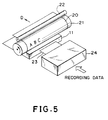
- Fig. 5 is a schematic perspective view of an ink jet recording apparatus having an ink jet head used therefor and constructed according to a second example, particularly showing essential components constituting the recording apparatus.
- a recording medium 20 such as a sheet of recording paper or the like is transported in the condition that the recording medium 20 is wound around a platen 21.
- the recording medium 20 is stepwise conveyed in the D arrow-marked direction.
- an ink droplet is ejected from the ink jet head 11 toward the recording medium 20 so as to record various items and others, images or the like with the ejected ink droplets.
- the ink jet head 11 adapted to eject an ink droplet in conformity with the aforementioned acoustic principle is immovably mounted on a case of the recording apparatus.
- Recording data inputted from a host computer or the like are converted into signals for selectively driving a plurality of piezo-electric elements to be described later for the ink jet head 11 in a head driving circuit 24, and subsequently, the signals are fed to the ink jet head 11 via a cable 23 as driving signals.
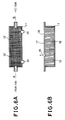
- Fig. 6A is a schematic plan view of the ink jet head 11 shown in Fig. 5, and Fig. 6B is a sectional view of the ink jet head 11 taken along line A - B in Fig. 6A.
- ink is supplied to the ink jet head 11 from the A side of the latter and then discharged from the B side of the same.
- a quantity of the ink received in the ink jet head 11 is detected by a first ink liquid plane sensor 13 and a second ink liquid plane sensor 14.
- ink is additionally supplied to the ink jet head 11 from the A side of the latter with the aid of an ink supplying mechanism (not shown).
- Each of the ink liquid plane sensors 13 and 14 is prepared in the form of a reflection type photosensor so that it is practically used for detecting whether the ink received in the ink jet head 11 reaches a predetermined level or not.
- each piezo-electric element 12 is designed in the form of an elongated column having a square cross-sectional shape, and as shown in Fig. 6A, a number of piezo-electric elements 12 each designed in that way are arranged in the form of a matrix composed of a plurality of lines and a plurality of rows extending at a right angle relative to the lines.
- a thin film layer 17 is kept contact with an end surface of each of the piezo-electric elements 12 arranged in the above-described manner.
- the placement of the thin film layer 17 in that way is intended to prevent the ink from coming in direct contact with the piezo-electric elements 12, to maintain proper acoustic impedance matching in order to allow a series of pressure waves generated as the piezo-electric elements 12 are vibrated to effectively propagate in the ink, and to protect the piezo-electric elements from the ink.
- Fig. 6B shows the operative state of the ink jet head 11 that an ink droplet 15 is ejected in the arrow-marked direction.
- a certain magnitude of AC voltage is preliminarily applied to each of the piezo-electric elements 12 located below the ejected ink droplet 15, and the upper end surfaces of the respective piezo-electric elements 12 arranged in the side-by-side relationship form a single slight concave surface as a whole.
- an AC voltage having a high frequency is applied to each of the piezo-electric elements 12, causing the latter to be vibrated.
- the slight concave surface defined by the upper end surfaces of the respective piezo-electric elements 12 in the above-described matter is intended to collectively concentrate the pressure waves irradiated from the respective piezo-electric elements 12 at the positions located in the vicinity of the ink liquid plane 16 as the piezo-electric elements 12 are vibrated.
- the head driving circuit 24 is activated, and subsequently, when an AC voltage having a comparative low frequency is applied to the respective piezo-electric elements 12, the positions of the upper end surfaces of the piezo-electric elements are properly controlled by the controller (not shown) so as to form a slight concave surface over the upper end surfaces of the piezo-electric elements 12.
- the controller not shown
- the piezo-electric elements 12 forming the concave surface the latter are vibrated, causing the ink to resonate in response to the vibrations.
- a volume of each ink droplet to be ejected from the ink jet head 11 can be controlled by the controller (not shown) by controlling the extent of deformation of the slight concave surface extending over the upper end surfaces of the piezo-electric elements 12.
- the volume of each ejected ink droplet can be maximized by adequately determining the extent of deformation of the slight concave surface.
- the extent of deformation of the slight concave surface is enlarged in excess of the extent available at the time of maximum deformation of the same or in the case that it is reduced in excess of the same, a volume of each ejected ink droplet is reduced.
- any ink droplet is not ejected from the ink jet head 11 even when each of the piezo-electric elements 12 is driven by an AC voltage having a comparatively high frequency.
- the ink jet head 11 makes it possible to control a volume of each ejected ink droplet as desired, each recording operation can be achieved in a multi-gray level mode while the size of an ink dot recorded on a recording medium is correspondingly controlled by the controller (not shown).
- a second scanning operation and subsequent ones are repeated in the same manner as mentioned above, and at the same time, the recording medium 20 is stepwise conveyed further every time each scanning operation is completed, whereby various items such as characters, images or the like can be recorded over the whole area of the recording medium 20 by repeating the aforementioned recording operation.
- Fig. 7 is a schematic perspective view of a piezo-electric element employable for practicing the second example particularly showing a three-dimensional configuration thereof.
- the piezo-electric element designated by reference numeral 12 is designed in the form of an elongated column having a square cross-sectional shape and includes two electrodes 12A, 12A on two side surfaces thereof facing to each other.
- each of the electrodes 12A is identified by a plurality of hatched lines, and the direction of polarization is oriented in the same direction as that of each electrode 12A.
- a strain of each piezo-electric element 12 appears in the F arrow-marked direction orienting at a right angle relative to the direction of each electrode 12A (i.e., vertical deformation of the piezo-electric element 12 is caused in-the F arrow-marked direction) .
- a number of piezo-electric elements 12 are two-dimensionally arranged in the ink jet head 11. Additionally, a sealing member (not shown) is sealably disposed between adjacent piezo-electric elements 12 to serve not only as an electrical insulative member but also as a reinforcing member for each piezo-electric element 12.
- each piezo-electric element is designed in the form of an elongated column having a square cross-sectional shape such that it is strained or deformed in the direction orienting at a right angle relative to the direction of polarization.
- a piezo-electric element may be designed in a laminated structure including a plurality of electrodes and a plurality of piezo-electric elements alternately laminated one above another such that it is strained or deformed in the same direction as that of polarization (i.e., in the transverse direction).
- An advantageous effect of the piezo-electric element constructed according to the modified example is that a value of AC voltage for deforming a group of piezo-electric elements so as to form a slight concave surface with them can be set to be comparatively small.
- only one ink droplet is ejected from the ink jet head 11 at a certain same time.
- a plurality of ink droplets e.g., two ink droplets may simultaneously be ejected from the ink jet head 11.
- Fig. 9 shows the case that two ink droplets are ejected from a ink jet head at a certain same time.
- the head driving circuit 24 is activated to control a magnitude of AC voltage to be applied to a group of piezo-electric elements with the aid of the controller (not shown) in such a manner as to simultaneously eject two ink droplets from an ink jet head 11.
- the controller not shown
- one ink droplet may be ejected from the ink jet head 11 with very short delay from other ink droplet or the remaining ink droplets.
- Fig. 10 is a schematic perspective view of an ink jet recording apparatus constructed according to a second embodiment of the present invention.
- the second embodiment of the present invention is practiced by combining the technical concept of the first embodiment of the present invention with the technical concept of the second example.
- a plurality of piezo-electric elements are crosswise arranged in an ink jet head 11 in the same manner as shown in Fig. 6A and Fig. 6B, and when ink droplets are ejected from the ink jet head 11, a high voltage generating circuit 8 is activated to generate an electric field effective between an ink liquid plane in the ink jet head 11 and a recording medium 20 such as a sheet of recording paper or the like.
- a film 17 as shown in Fig. 6B can be employed as an electrode for generating an electric field on the ink jet head 11 side.
- the electric field is basically generated within the range corresponding to the whole ink liquid plane in the ink jet head 11 but the electrode on the ink jet head 11 side may be divided into a plurality of electrode segments, e.g., by combining the film 17 with a plurality of wiring conductors arranged in a matrix-shaped pattern.
- a plurality of local electric fields can be generated, and moreover, the direction of orienting of each local electric field can be controlled by the controller (not shown) as desired in order to control the position where each ink droplet is shot onto the recording medium 20 at a higher accuracy.
- An electric field is formed between an ink jet recording head (11) and a recording medium (20) on a platen (21) so that a certain intensity of force effective in the direction orientating toward the recording medium (20) is applied to an ink droplet in the presence of the electric field.
- a certain intensity of force effective in the direction orientating toward the recording medium (20) is applied to an ink droplet in the presence of the electric field.
Claims (6)
- Dispositif à jet d'encre utilisant une tête à jet d'encre (11) pour éjecter de l'encre (10) à partir d'un plan liquide d'encre (16) de la tête à jet d'encre (11) en utilisant un effet de concentration collective d'une série d'ondes se propageant dans l'encre, l'encre étant éjectée à partir de la tête à jet d'encre (11) vers un support (20), ledit dispositif comportantdes moyens d'entraínement (24, 12) pour produire la série d'ondes dans ladite tête à jet d'encre (11) de manière à éjecter de l'encre, etdes moyens (6) pour former, au moment de l'éjection d'encre à partir de la tête à jet d'encre, un champ électrique entre le milieu (20) et ladite tête à jet d'encre (11) de manière à appliquer une force sur ladite encre,lesdits moyens (6) formant le champ électrique en créant une différence de tension entre le support (20) et ladite tête à jet d'encre (11), ladite différence de tension étant provoquée par une impulsion de tension produite par un circuit générant une tension (8), et ladite différence de tension est produite sensiblement en même temps que l'instant d'application d'une tension d'entraínement, ou légèrement avant, par lesdits moyens d'entraínement (24, 12) dans le but d'éjecter de l'encre.
- Dispositif à jet d'encre selon la revendication 1, caractérisé en ce que ladite différence de tension prédéterminée est provoquée par une impulsion de tension produite par le circuit générant une tension (8), et une autre différence de tension ayant une valeur de tension différente l'impulsion de tension provenant de ladite différence de tension prédéterminée est produite lorsque aucune encre n'est éjectée.
- Dispositif à jet d'encre selon la revendication 2, caractérisé en ce que la valeur de tension et/ou la largeur de l'impulsion de tension produite lorsque l'encre est éjectée peut être modifiée.
- Dispositif à jet d'encre selon la revendication 3, caractérisé en ce que ladite tête à jet d'encre (11) est utilisée pour réaliser un enregistrement sur un support d'enregistrement (20) en tant que support, le support d'enregistrement étant déplacé tout en réalisant l'enregistrement.
- Dispositif à jet d'encre selon la revendication 4, caractérisé en ce que lesdits moyens d'entraínement (24, 12) ont un élément de conversion électromécanique (12) qui produit la série d'ondes se propageant dans l'encre.
- Dispositif à jet d'encre selon l'une quelconque des revendications précédentes, comportant de plusune pluralité d'éléments de conversion électromécanique (12) dont chacun peut être déformé pour produire la série d'ondes, lesdits éléments étant agencés dans une forme prédéterminée, etdes électrodes (12A) pour appliquer une énergie électrique à ladite pluralité d'éléments de conversion électromécanique (12) pour être sélectivement entraínés de manière à être déformés, etdes moyens de commande d'éjection pour commander lesdits moyens d'entraínement (24, 12) de sorte qu'un nombre prédéterminé d'éléments de conversion électromécanique (12) concernés par l'éjection d'encre forment une surface concave, et ledit nombre prédéterminé d'éléments de conversion électromécanique (12) concernés par l'éjection d'encre vibrent à une fréquence plus élevée que la fréquence existant lorsque ladite surface concave est formée,lesdits moyens d'entraínement (24, 12) entraínant de manière sélective ladite pluralité d'éléments de conversion électromécanique (12) par l'intermédiaire desdites électrodes (12A).
Applications Claiming Priority (6)
| Application Number | Priority Date | Filing Date | Title |
|---|---|---|---|
| JP1333593A JPH06218926A (ja) | 1993-01-29 | 1993-01-29 | インクジェット記録ヘッドおよび該ヘッドを用いたインクジェット記録装置 |
| JP1333493 | 1993-01-29 | ||
| JP1333593 | 1993-01-29 | ||
| JP13335/93 | 1993-01-29 | ||
| JP1333493A JPH06218930A (ja) | 1993-01-29 | 1993-01-29 | インクジェット記録装置 |
| JP13334/93 | 1993-01-29 |
Publications (2)
| Publication Number | Publication Date |
|---|---|
| EP0608879A1 EP0608879A1 (fr) | 1994-08-03 |
| EP0608879B1 true EP0608879B1 (fr) | 1999-10-27 |
Family
ID=26349113
Family Applications (1)
| Application Number | Title | Priority Date | Filing Date |
|---|---|---|---|
| EP94101196A Expired - Lifetime EP0608879B1 (fr) | 1993-01-29 | 1994-01-27 | Appareil à jet d'encre |
Country Status (3)
| Country | Link |
|---|---|
| US (1) | US5898446A (fr) |
| EP (1) | EP0608879B1 (fr) |
| DE (1) | DE69421301T2 (fr) |
Families Citing this family (19)
| Publication number | Priority date | Publication date | Assignee | Title |
|---|---|---|---|---|
| US5975683A (en) * | 1995-06-07 | 1999-11-02 | Xerox Corporation | Electric-field manipulation of ejected ink drops in printing |
| JP3161404B2 (ja) | 1997-12-26 | 2001-04-25 | 日本電気株式会社 | インク滴径制御方法およびインクジェット記録ヘッド |
| US6312104B1 (en) | 1998-06-17 | 2001-11-06 | Xerox Corporation | Reduction of spot misplacement through electrostatic focusing of uncharged drops |
| DE19946823A1 (de) | 1999-09-30 | 2001-04-05 | Kammann Maschf Werner | Verfahren und Vorrichtung zum Dekorieren von Einzelobjekten |
| US6414051B1 (en) * | 2000-02-01 | 2002-07-02 | Xerox Corporation | Acoustic printing inks containing bis(carbamates) |
| US6623700B1 (en) * | 2000-11-22 | 2003-09-23 | Xerox Corporation | Level sense and control system for biofluid drop ejection devices |
| US6861034B1 (en) * | 2000-11-22 | 2005-03-01 | Xerox Corporation | Priming mechanisms for drop ejection devices |
| US6872320B2 (en) * | 2001-04-19 | 2005-03-29 | Xerox Corporation | Method for printing etch masks using phase-change materials |
| US6742884B2 (en) * | 2001-04-19 | 2004-06-01 | Xerox Corporation | Apparatus for printing etch masks using phase-change materials |
| WO2003006164A1 (fr) * | 2001-07-11 | 2003-01-23 | Universisty Of Southern California | Synthese de sonde d'adn sur puce realisee sur demande par un reseau d'ejecteurs de systemes microelectromagnetiques |
| US6972261B2 (en) * | 2002-06-27 | 2005-12-06 | Xerox Corporation | Method for fabricating fine features by jet-printing and surface treatment |
| US20060240065A1 (en) * | 2005-04-26 | 2006-10-26 | Yung-Ming Chen | Compositions for medical devices containing agent combinations in controlled volumes |
| US7481112B2 (en) * | 2004-09-30 | 2009-01-27 | University Of Southern California | Silicon inertial sensors formed using MEMS |
| ATE524322T1 (de) | 2004-10-07 | 2011-09-15 | Fujifilm Corp | Tintenstrahlaufzeichnungsgerät und verfahren |
| US7976891B1 (en) | 2005-12-16 | 2011-07-12 | Advanced Cardiovascular Systems, Inc. | Abluminal stent coating apparatus and method of using focused acoustic energy |
| US7775178B2 (en) * | 2006-05-26 | 2010-08-17 | Advanced Cardiovascular Systems, Inc. | Stent coating apparatus and method |
| US7719170B1 (en) | 2007-01-11 | 2010-05-18 | University Of Southern California | Self-focusing acoustic transducer with fresnel lens |
| US7980672B2 (en) * | 2007-05-11 | 2011-07-19 | Canon Kabushiki Kaisha | Inkjet printing apparatus and printing method |
| JP2008279676A (ja) * | 2007-05-11 | 2008-11-20 | Canon Inc | インクジェット記録装置および記録方法 |
Family Cites Families (12)
| Publication number | Priority date | Publication date | Assignee | Title |
|---|---|---|---|---|
| US4719480A (en) * | 1986-04-17 | 1988-01-12 | Xerox Corporation | Spatial stablization of standing capillary surface waves |
| US4751530A (en) * | 1986-12-19 | 1988-06-14 | Xerox Corporation | Acoustic lens arrays for ink printing |
| JPS63166546A (ja) * | 1986-12-19 | 1988-07-09 | ゼロックス コーポレーション | 音響印刷用希薄アレイ |
| JPH0733085B2 (ja) * | 1989-02-18 | 1995-04-12 | シャープ株式会社 | インクジェットヘッド |
| JPH0764060B2 (ja) * | 1989-06-09 | 1995-07-12 | シャープ株式会社 | インクジェットプリンタ |
| JPH03155948A (ja) * | 1989-11-13 | 1991-07-03 | Seiko Epson Corp | インクジェットヘッド |
| JPH03155953A (ja) * | 1989-11-13 | 1991-07-03 | Seiko Epson Corp | インクジェットヘッド |
| JPH07125193A (ja) * | 1989-12-15 | 1995-05-16 | Tektronix Inc | ドロップ・オン・デマンド型インク・ジェット・プリ ント・ヘッド及びその動作方法 |
| JPH03243358A (ja) * | 1990-02-20 | 1991-10-30 | Sharp Corp | インクジェット記録ヘッド用圧電アクチュエータ |
| JP3041952B2 (ja) * | 1990-02-23 | 2000-05-15 | セイコーエプソン株式会社 | インクジェット式記録ヘッド、圧電振動体、及びこれらの製造方法 |
| JPH04168050A (ja) * | 1990-11-01 | 1992-06-16 | Nec Eng Ltd | 印刷ヘッド |
| US5229793A (en) * | 1990-12-26 | 1993-07-20 | Xerox Corporation | Liquid surface control with an applied pressure signal in acoustic ink printing |
-
1994
- 1994-01-27 DE DE69421301T patent/DE69421301T2/de not_active Expired - Fee Related
- 1994-01-27 EP EP94101196A patent/EP0608879B1/fr not_active Expired - Lifetime
-
1997
- 1997-02-19 US US08/801,366 patent/US5898446A/en not_active Expired - Fee Related
Non-Patent Citations (1)
| Title |
|---|
| K.A. KRAUSE: "Focusing Ink Jet Head", IBM TECHNICAL DISCLOSURE BULLETIN, vol. 16, no. 2, pages 1168 * |
Also Published As
| Publication number | Publication date |
|---|---|
| DE69421301D1 (de) | 1999-12-02 |
| US5898446A (en) | 1999-04-27 |
| DE69421301T2 (de) | 2000-04-13 |
| EP0608879A1 (fr) | 1994-08-03 |
Similar Documents
| Publication | Publication Date | Title |
|---|---|---|
| EP0608879B1 (fr) | Appareil à jet d'encre | |
| US4748461A (en) | Capillary wave controllers for nozzleless droplet ejectors | |
| JP4543284B2 (ja) | ミスト噴射装置及び方法並びに画像形成装置 | |
| JP2715001B2 (ja) | 2つのu字型チャンネル駆動装置を持つ高密度インクジェットプリンタヘッド | |
| JP2009154512A (ja) | インクジェット記録装置 | |
| US7758159B2 (en) | Mist spraying apparatus and image forming apparatus | |
| US6036302A (en) | Inkjet recording apparatus | |
| US7611228B2 (en) | Mist ejection head and image forming apparatus comprising same | |
| JPH10166567A (ja) | インクジェット記録装置 | |
| JP3324429B2 (ja) | インクジェット記録装置 | |
| US7604329B2 (en) | Liquid ejection head and image forming apparatus | |
| JP2006150816A (ja) | インクジェット記録装置及び波形決定方法 | |
| JP3262009B2 (ja) | 画像形成装置 | |
| JP2001150684A (ja) | 印刷装置の液滴配置誤差の低減方法および装置 | |
| EP0234718B1 (fr) | Ejecteurs de gouttelettes | |
| JP2003011339A (ja) | インクジェット記録装置 | |
| JPH0538809A (ja) | インクジエツトヘツド | |
| US7665831B2 (en) | Image forming apparatus and method of driving ink discharge | |
| JPH06218926A (ja) | インクジェット記録ヘッドおよび該ヘッドを用いたインクジェット記録装置 | |
| JPH0510228B2 (fr) | ||
| JPH0911459A (ja) | インクジェット記録装置 | |
| JP4557021B2 (ja) | 液滴噴射装置 | |
| JPS6056629B2 (ja) | 画像記録方法 | |
| JPH10250068A (ja) | インクジェット記録装置 | |
| JPH05193139A (ja) | インクジェット印刷機 |
Legal Events
| Date | Code | Title | Description |
|---|---|---|---|
| PUAI | Public reference made under article 153(3) epc to a published international application that has entered the european phase |
Free format text: ORIGINAL CODE: 0009012 |
|
| AK | Designated contracting states |
Kind code of ref document: A1 Designated state(s): DE FR GB IT |
|
| 17P | Request for examination filed |
Effective date: 19941220 |
|
| 17Q | First examination report despatched |
Effective date: 19951206 |
|
| GRAG | Despatch of communication of intention to grant |
Free format text: ORIGINAL CODE: EPIDOS AGRA |
|
| GRAG | Despatch of communication of intention to grant |
Free format text: ORIGINAL CODE: EPIDOS AGRA |
|
| GRAH | Despatch of communication of intention to grant a patent |
Free format text: ORIGINAL CODE: EPIDOS IGRA |
|
| GRAH | Despatch of communication of intention to grant a patent |
Free format text: ORIGINAL CODE: EPIDOS IGRA |
|
| GRAA | (expected) grant |
Free format text: ORIGINAL CODE: 0009210 |
|
| AK | Designated contracting states |
Kind code of ref document: B1 Designated state(s): DE FR GB IT |
|
| PG25 | Lapsed in a contracting state [announced via postgrant information from national office to epo] |
Ref country code: IT Free format text: LAPSE BECAUSE OF FAILURE TO SUBMIT A TRANSLATION OF THE DESCRIPTION OR TO PAY THE FEE WITHIN THE PRE;WARNING: LAPSES OF ITALIAN PATENTS WITH EFFECTIVE DATE BEFORE 2007 MAY HAVE OCCURRED AT ANY TIME BEFORE 2007. THE CORRECT EFFECTIVE DATE MAY BE DIFFERENT FROM THE ONE RECORDED.SCRIBED TIME-LIMIT Effective date: 19991027 Ref country code: FR Free format text: LAPSE BECAUSE OF FAILURE TO SUBMIT A TRANSLATION OF THE DESCRIPTION OR TO PAY THE FEE WITHIN THE PRESCRIBED TIME-LIMIT Effective date: 19991027 |
|
| REF | Corresponds to: |
Ref document number: 69421301 Country of ref document: DE Date of ref document: 19991202 |
|
| EN | Fr: translation not filed | ||
| PLBE | No opposition filed within time limit |
Free format text: ORIGINAL CODE: 0009261 |
|
| STAA | Information on the status of an ep patent application or granted ep patent |
Free format text: STATUS: NO OPPOSITION FILED WITHIN TIME LIMIT |
|
| 26N | No opposition filed | ||
| REG | Reference to a national code |
Ref country code: GB Ref legal event code: IF02 |
|
| PGFP | Annual fee paid to national office [announced via postgrant information from national office to epo] |
Ref country code: DE Payment date: 20060119 Year of fee payment: 13 |
|
| PGFP | Annual fee paid to national office [announced via postgrant information from national office to epo] |
Ref country code: GB Payment date: 20060125 Year of fee payment: 13 |
|
| PG25 | Lapsed in a contracting state [announced via postgrant information from national office to epo] |
Ref country code: DE Free format text: LAPSE BECAUSE OF NON-PAYMENT OF DUE FEES Effective date: 20070801 |
|
| GBPC | Gb: european patent ceased through non-payment of renewal fee |
Effective date: 20070127 |
|
| PG25 | Lapsed in a contracting state [announced via postgrant information from national office to epo] |
Ref country code: GB Free format text: LAPSE BECAUSE OF NON-PAYMENT OF DUE FEES Effective date: 20070127 |