EP0608397B1 - Machine et procede pour appliquer une etiquette informative sur un goulot de bouteille - Google Patents
Machine et procede pour appliquer une etiquette informative sur un goulot de bouteille Download PDFInfo
- Publication number
- EP0608397B1 EP0608397B1 EP93916396A EP93916396A EP0608397B1 EP 0608397 B1 EP0608397 B1 EP 0608397B1 EP 93916396 A EP93916396 A EP 93916396A EP 93916396 A EP93916396 A EP 93916396A EP 0608397 B1 EP0608397 B1 EP 0608397B1
- Authority
- EP
- European Patent Office
- Prior art keywords
- neck
- booklet
- elastic band
- band
- slide plate
- Prior art date
- Legal status (The legal status is an assumption and is not a legal conclusion. Google has not performed a legal analysis and makes no representation as to the accuracy of the status listed.)
- Expired - Lifetime
Links
- 238000000034 method Methods 0.000 title claims description 12
- 239000004744 fabric Substances 0.000 claims description 5
- 239000011248 coating agent Substances 0.000 claims description 3
- 238000000576 coating method Methods 0.000 claims description 3
- 210000003739 neck Anatomy 0.000 description 120
- 235000013361 beverage Nutrition 0.000 description 10
- 238000004519 manufacturing process Methods 0.000 description 4
- 239000013013 elastic material Substances 0.000 description 2
- 239000007787 solid Substances 0.000 description 2
- 238000010276 construction Methods 0.000 description 1
- 230000000694 effects Effects 0.000 description 1
- 239000000463 material Substances 0.000 description 1
- 238000012986 modification Methods 0.000 description 1
- 230000004048 modification Effects 0.000 description 1
- 238000003825 pressing Methods 0.000 description 1
- 230000005855 radiation Effects 0.000 description 1
- 239000012858 resilient material Substances 0.000 description 1
- 230000000717 retained effect Effects 0.000 description 1
- 238000007789 sealing Methods 0.000 description 1
Images


Classifications
-
- B—PERFORMING OPERATIONS; TRANSPORTING
- B65—CONVEYING; PACKING; STORING; HANDLING THIN OR FILAMENTARY MATERIAL
- B65B—MACHINES, APPARATUS OR DEVICES FOR, OR METHODS OF, PACKAGING ARTICLES OR MATERIALS; UNPACKING
- B65B61/00—Auxiliary devices, not otherwise provided for, for operating on sheets, blanks, webs, binding material, containers or packages
- B65B61/20—Auxiliary devices, not otherwise provided for, for operating on sheets, blanks, webs, binding material, containers or packages for adding cards, coupons or other inserts to package contents
- B65B61/202—Auxiliary devices, not otherwise provided for, for operating on sheets, blanks, webs, binding material, containers or packages for adding cards, coupons or other inserts to package contents for attaching articles to the outside of a container
-
- B—PERFORMING OPERATIONS; TRANSPORTING
- B65—CONVEYING; PACKING; STORING; HANDLING THIN OR FILAMENTARY MATERIAL
- B65C—LABELLING OR TAGGING MACHINES, APPARATUS, OR PROCESSES
- B65C7/00—Affixing tags
-
- Y—GENERAL TAGGING OF NEW TECHNOLOGICAL DEVELOPMENTS; GENERAL TAGGING OF CROSS-SECTIONAL TECHNOLOGIES SPANNING OVER SEVERAL SECTIONS OF THE IPC; TECHNICAL SUBJECTS COVERED BY FORMER USPC CROSS-REFERENCE ART COLLECTIONS [XRACs] AND DIGESTS
- Y10—TECHNICAL SUBJECTS COVERED BY FORMER USPC
- Y10S—TECHNICAL SUBJECTS COVERED BY FORMER USPC CROSS-REFERENCE ART COLLECTIONS [XRACs] AND DIGESTS
- Y10S29/00—Metal working
- Y10S29/044—Vacuum
-
- Y—GENERAL TAGGING OF NEW TECHNOLOGICAL DEVELOPMENTS; GENERAL TAGGING OF CROSS-SECTIONAL TECHNOLOGIES SPANNING OVER SEVERAL SECTIONS OF THE IPC; TECHNICAL SUBJECTS COVERED BY FORMER USPC CROSS-REFERENCE ART COLLECTIONS [XRACs] AND DIGESTS
- Y10—TECHNICAL SUBJECTS COVERED BY FORMER USPC
- Y10T—TECHNICAL SUBJECTS COVERED BY FORMER US CLASSIFICATION
- Y10T29/00—Metal working
- Y10T29/49—Method of mechanical manufacture
- Y10T29/49826—Assembling or joining
- Y10T29/49863—Assembling or joining with prestressing of part
- Y10T29/4987—Elastic joining of parts
-
- Y—GENERAL TAGGING OF NEW TECHNOLOGICAL DEVELOPMENTS; GENERAL TAGGING OF CROSS-SECTIONAL TECHNOLOGIES SPANNING OVER SEVERAL SECTIONS OF THE IPC; TECHNICAL SUBJECTS COVERED BY FORMER USPC CROSS-REFERENCE ART COLLECTIONS [XRACs] AND DIGESTS
- Y10—TECHNICAL SUBJECTS COVERED BY FORMER USPC
- Y10T—TECHNICAL SUBJECTS COVERED BY FORMER US CLASSIFICATION
- Y10T29/00—Metal working
- Y10T29/53—Means to assemble or disassemble
- Y10T29/53313—Means to interrelatedly feed plural work parts from plural sources without manual intervention
- Y10T29/53322—Means to assemble container
- Y10T29/5333—Label to container
-
- Y—GENERAL TAGGING OF NEW TECHNOLOGICAL DEVELOPMENTS; GENERAL TAGGING OF CROSS-SECTIONAL TECHNOLOGIES SPANNING OVER SEVERAL SECTIONS OF THE IPC; TECHNICAL SUBJECTS COVERED BY FORMER USPC CROSS-REFERENCE ART COLLECTIONS [XRACs] AND DIGESTS
- Y10—TECHNICAL SUBJECTS COVERED BY FORMER USPC
- Y10T—TECHNICAL SUBJECTS COVERED BY FORMER US CLASSIFICATION
- Y10T29/00—Metal working
- Y10T29/53—Means to assemble or disassemble
- Y10T29/53478—Means to assemble or disassemble with magazine supply
Definitions
- the present invention is directed to a neck booklet machine and method which is adapted to place an elastic band, string or the like connected to a neck booklet around a neck of a container, such as a bottle, beverage container or the like.
- Advertising devices such as neck booklets having closed elastic bands, closed loops or the like connected thereto, are desirably placed around the neck of beverage containers to convey a particular advertising message for the particular beverage within the container.
- Proskauer, U.S. Patent No. 1,994,961, entitled “ADVERTISING DEVICE” describes a container having a neck portion with a booklet.
- Means for securing the booklet include a cord, or the like, passing through the booklet and positioned around the neck portion of the container. (Col. 2, lines 9-13.)
- Staves fails to describe a device to accomplish these tasks.
- the weight of the booklet dragging along a rail creates frictional resistance thereby causing a slight tensioning in the cord so as to remove slack from the cord. This prevents the cord from becoming dislodged from the body portion of the closure and allows the presser wheel to fully insert the closure.
- the manual placement of neck booklets becomes more difficult and often requires additional people to perform the manual placement function.
- Machines have also been designed to position elastic type members around the cylindrical objects, such as expandable neck labels around the neck of a container.
- elastic type members such as expandable neck labels around the neck of a container.
- U.S. Patent No. 4,215,460 entitled “APPARATUS AND METHOD FOR ASSEMBLYING TUBULAR SLEEVE PREFORMS AND CONTAINERS” discloses a device to place a heat-shrinkable tubular sleeve about the neck of a container.
- the tubular sleeve is flat folded in a holder having dimensions complemental to the retained flattened stack of sleeves (Col. 3, line 55-57).
- the flattened tubular sleeve is gripped by a pair of vacuum cups moving downwardly and divergently along chains to open the flattened sleeve.
- the opened tubular sleeve is placed on a cylindrical mandrel to more fully open the tubular sleeve prior to its being mounted telescopically by a stripper element on the container neck portion of the container.
- Hoffman et al. U.S. Patent No. 3,186,333, entitled “RUBBER BAND STRETCHING APPARATUS”, discloses a device for wrapping elastic bands around an article.
- the elastic bands are supplied in a stacked relationship, such as having adjacent bands connected to each other by a strip.
- a feeder blade grasps the lowermost band so that four expander fingers are positioned with the band.
- the outmost fingers are shifted downwardly and outwardly, the major component of their movement being horizontal.
- the innermost fingers are shifted downwardly and outwardly, with the major component of their movement being downwardly.
- the curved and angulated configuration of the release fingers allows the elastic band to slip from engagement with them and engage the article.
- Strout U.S. Patent No. 2,103,302, entitled “BAND APPLYING MACHINE” describes a machine for applying a tubular banding sleeve to a neck of a container.
- a magazine is disposed to store collapsed or flat sleeves.
- a first movable suction member withdraws a sleeve from the magazine and positions it over the neck of the container.
- Second suction members in cooperation and conjunction with the first suction member effects the opening of the sleeve.
- the sleeve is opened by an air jet via tubes which force air into the interior of the banding sleeve.
- An expansible member first engages the sleeve as a cone shaped member and then expands itself and the sleeve into a cylindrical shape. This expands the sleeve into an open position for positioning onto the neck of the container.
- the label By applying pressure to the label perpendicular to the axis of the container, the label is secured to the container so that the container may be removed from the label applicator.
- a resilient expandable solid cone may be used in lieu of ring and expandable fingers.
- a machine for positioning a booklet having a band around a container comprising:
- the slide plate terminates in a manner so that the carrier pads release the booklet once the booklet is affixed around the next of the container.
- the machine positions neck booklets having an elastic band and includes a curved magazine defined to receive a plurality of neck booklets.
- a vacuum cup is positioned to sequentially remove in series neck booklets from the curved magazine and position the booklets along a slide plate.
- Carrier pads are disposed to engage the neck booklet and incrementally transport the neck booklet along the slide plate.
- the carrier pads in combination with a vacuum nozzle maintain the elastic band in a downwardly projecting open loop.
- a needle point is disposed to project into the open loop of the elastic band as the elastic band moves along the slide plate.
- An opening horn is affixed to the needle point and is disposed to gradually expand the elastic band as the neck booklet moves along the slide plate.
- Application fingers are positioned to receive the expanded elastic band with fingers having at least three points to define an opening suitable for fitting the elastic band around the neck of the container as the carrier pads incrementally transport the neck booklet along the carrier plate and elastic band along the application fingers.
- the neck booklet machine additionally comprises either a conveyor or rotatable table having a plurality of containers positioned on the conveyor or rotatable table.
- the application fingers are disposed in a manner to incrementally position the elastic bands around the containers.
- a neck booklet having an elastic band around a neck of a container comprising:
- the above method additionally includes the steps of terminating the slide plate in a manner so that the carrier pads release the booklet once the booklet is affixed around the neck of the container.
- a machine for positioning a booklet having a band around a container comprising:
- the neck booklet machine of this invention provides important advantages. It can precisely and accurately place a neck booklet on the neck of a beverage container while the beverage container is moving along a conveyor belt. Additionally, it can handle a wide variety of shapes and sizes of necks of beverage containers moving at a range of production line speeds. Further, the neck booklet machine of the present invention provides a rugged construction which is easy to repair and maintain, e.g., a neck booklet jamming along the slide rail.
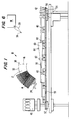
- the neck booklet machine 10 includes a curved magazine 12 holding a plurality of booklets or neck booklets 14.
- the neck booklets 14 are generally vertically positioned within a slide plate 16 positioned at the bottom of the curved magazine 12.
- the neck booklets 14 have elastic bands 20 or strings, cords or the like tied through a punched hole 22 in the neck booklet 14.
- the elastic band 20 includes a fabric or cloth coating positioned over an elastic material.
- the elastic material is about 1 mm in diameter with the fabric coating about 0.5 mm to provide an elastic band of about 1.5 mm in diameter.
- elastic it is intended to include any expandable-resilient material which may be suitably expanded to be positioned over a neck of a container and resiliently contract therearound once expansion forces are released, or contracted due to the application of physical conditions or phenomena such as heat, pressure, UV radiation, etc.
- the neck booklets 14 are vertically stacked in the curved magazine 12 and sequentially pulled in series from the magazine by a vacuum cup 24, or other removal means such as frictional pads.
- the shape of the curved magazine 12 matches the natural curvature of a stack of neck booklets 14 having an elastic band 20 positioned on one end 26 to render one end of the booklet thicker than the other end 28 of the booklet.
- the bottom 30 of the curved magazine 12 includes an arc-shaped opening 32 to allow the elastic bands 20 to hang free in an essentially vertical position.
- the elastic bands 20 have a knot 34 positioned therein which provides a length of about 11 ⁇ 2 inches and forms a closed loop 36a of about 3 inches in diameter.
- a knot tying machine for elastic bands suitable for use in this invention is a model #185 Whirlwind knot tying machine available from the Bobst Corporation in New Jersey.
- the booklet 14 is picked up by a carrier pad, such as a carrier pressure pad 40, and held against and transported along a slide plate 42 toward a container transport means, such as a conveyor 46, having containers 44 positioned thereon.
- a carrier pad such as a carrier pressure pad 40
- An indexing drive motor 48 moves an endless flexible member, such as chain 50, upon which the carrier pads 40 are positioned.
- the chain 50 is positioned between drive rotational member 52 and idler rotation member 54, which moves the neck booklets 14 via the carrier pads 40 therebetween.
- a low vacuum nozzle 56 pulls and holds the closed loop 36a of the elastic band 20 down to a generally vertical position.
- This vacuum pull by the vacuum nozzle 56 in combination with the carrier pads 40 enables the closed loop 36a of the elastic band 20 to be picked up by a needle point 58.
- the loose elastic band 20 is held precisely below the neck booklet 14 on the slide plate 42.
- the opening horn 60 is carried on front support 62 and rear support 64 on the bottom 66 and sides 68 with a top opening 70 positioned to allow the elastic band 20 to pass over and around the opening horn 60, as shown in phantom lines and becomes an open loop 36b.
- the opening horn 60 is loosely supported by the two "U" shaped supports 62, 64 (or horse collars) to allow the thickness of the elastic band 20 to pass between the support members 62, 64 and the opening horn 60.
- the opening horn 60 is a generally conical shape having one plane generally parallel, or adjacent, to the axis or path of the slide bar 42.
- the elastic band 20 moves along the opening horn 60 to be stretched into an expanded position and form an open loop 36b.
- the opening horn 60 feeds the elastic band 14 into a plurality of application fingers 72, 74.
- the four application fingers 72a, 72b, 74a, 74b maintain the elastic band 20 in an expanded position, and when indexed to the next container 44 positioned along the conveyor 46, feed the expanded elastic band 20 onto the neck 76 of the container 44.
- the carrier pressure pads 40 release the neck booklet 14 at the end of the slide plate 42 at the precise time as the elastic band 20 is positioned over the neck 76 of the container 44 by the plurality of fingers 72a, 72b, 74a, 74b.
- the elastic band 20 is expanded from about 3 inches in circumference to about 4 inches in circumference.
- One of the application fingers 74b is a lesser length by distance "X" than the other three application fingers 72a, 72b, 74a to define the three points on the elastic band 20.
- the opening in the elastic band 20 defined by points 72a, 72b, 74a is suitable for fitting the elastic band 20 around the neck 76 of the container 44.
- the neck 76 of the container 44 is about 28 mm and the above expansion is suitable to position the elastic band 20 therearound.
- the number of application fingers may be reduced or increased depending upon the resiliency of the elastic band to be affixed around the neck 76 of the container 44.
- the incremental positioning of the neck booklets 14 with the elastic band 20 onto the neck 76 of containers 44 being transported on a conveyor or rotatable table is accomplished by use an indexing photo cell 80 coupled to the indexing drive motor 48.
- the indexing photo cell 80 precisely coordinates the movement of the carrier pressure pads 40 along the slide plate 42 as the containers 44 move under the plurality of application fingers 72, 74.
- Each continuous or sequential movement of the container 44 along the conveyor 46 brings about an incremental movement of the carrier pressure pads 40 along the slide plate 42 and the resulting positioning of the expanded elastic band 14 over the neck 76 of the container 44.
- the neck booklet machine 10 can handle a wide range of production line speeds with precision and accuracy.
- the present invention additionally comprises a method for positioning a neck booklet 14 having an elastic band 20 around a neck 76 of a container 44 comprising the steps of: providing a curved magazine 12 to receive a plurality of neck booklets 14; providing a vacuum cup 24 to sequentially remove in series neck booklets 14 from the curved magazine 12 and positioning the neck booklets 14 along a slide plate 42; providing a plurality of carrier pads 40 disposed to engage the neck booklet 14 between the carrier pads 40 and the slide plate 42, transporting incrementally the neck booklet 14 along the slide plate 42 via the carrier pads 40; providing a vacuum nozzle 56 in combination with the carrier pads 40 to maintain the elastic band 20 in a downwardly projecting closed loop 36a; providing a needle point 58 projecting into the closed loop 36a of the elastic band 20 as the elastic band 20 moves along the slide plate 42; providing an opening horn 60 affixed to the needle point 58 and disposed to gradually expand
- the neck booklet machine 10 of the present invention may be used to position an elastic band 20 around any cylindrical object or materials, such as containers, rolled papers, etc.
- a simple destructible card can be used as a carrier along the slide plate 42 of the neck booklet machine 10 to properly position the elastic band 14.
- the destructible card may be removed manually, or by a machine such as a rotating brush which bears against the destructible card.
- a plurality of the neck booklet machines 10 of the present invention may be ganged together in series to serve a plurality of moving conveyors 46 or rotatable tables having containers 44 positioned thereon.
- the opening horn 60 includes at least one "U" shaped support 65, the "U" shaped support 65 loosely supports the opening horn to allow the elastic band 20 to pass between the support and the opening horn 60, shown in phantom.
- the opening horn 60 may be supported by either air bearings or magnetic means in a manner to allow the elastic band to pass therebetween.
- one or two of the application fingers 72 or 74 may be affixed to the opening horn 60 to support the opening horn 60 in a manner to allow the elastic band 20 to pass between the supports 62, 64 and the opening horn 60 onto the application fingers 72, 74.
- This support of the opening horn 60 by the application fingers 72 or 74 is preferably in combination with the supports 62, 64 which are positioned on sides and bottom of the opening horn 60, but may be accomplished separately provided the application fingers 72, 74 are supported in a like manner as is the opening horn 60.
- the carrier pads 40 may comprise either pressure pads, friction pads or vacuum cups or other suitable means to transport the neck booklets 14.
- the opening horn 60 may define either a circular, square, triangular, oval or other suitable cross-section conformed to match the shape of the container 44 on which the neck booklet 14 is to be affixed.
- the cross-section of the opening horn 60 is matched to the cross section of the application fingers 72, 74 to assure ease of movement of the elastic band 20. More preferably, the opening horn 60 defines a cylindrically shaped solid cone having an angle less than 30°.
- the opening horn 60 may be defined by a plurality of opening horn fingers, illustrated by phantom lines 73a-g, with selected opening horn fingers 73a-g being coextensive with the application fingers 72a, 72b, 74a, 74b.
- the number of application fingers 72, 74 may be reduced or increased depending upon the resiliency of the elastic band 20 to be affixed around the neck 76 of the container 44, provided that the application fingers 72, 74 define at least three points 72a, 72b, 74a to receive the elastic band just prior to its placement on the neck 76 of the container 44.
- the application fingers 72a, 72b, 74a, 74b are defined to convey the elastic band 20 or loop 36a from the opening horn
- one of the application fingers 74b is a lesser length than the other three application fingers 72a, 72b, 74a to define the three points on the elastic band 14b.
- the open loop 36b in the elastic band 20 is suitable for fitting the elastic band 20 around the neck 76 of the container 44.
- the neck booklet machine 10' includes the curved magazine 12' and vacuum cup 24' as described above. Vacuum cup 24' positions neck booklets 14 between parallel endless members 100, 102, which are spaced apart and moved incrementally around pulleys 104, 106 and 110, 112, respectively.
- the endless parallel members 100, 102 function as the carrier pads 40 and slide plate 42 of the embodiment described in Figs. 1 and 2.
- the closed loop 36a of the elastic band 20 is pulled down in a vertical position by vacuum nozzle 56'.
- the closed loop 36a is grasped by two application fingers 72', 74' positioned on a rotating wheel 120 and expanded by relative motion of the application fingers 72', 74' to the endless members 100, 102 into an open loop 36b by the rotational forces of the rotating wheel 120 on the application fingers 72', 74'.
- the plurality of application fingers 72', 74' are spaced about the rotating wheel 120, which is timed to incrementally place the open loop 36a around the necks 76 of containers 44 positioned on conveyor 46.
- the rotating wheel performs the function of the needle point 58 and opening horn 60 of the embodiment described in Figs. 1 and 2.
- At least one of the application fingers is of a bladelike or arcuate structure so that the application fingers 72', 74' define a minimum of three points to properly place the elastic band 20 around the neck of the container 44.
- the neck booklet machine 10 features the combination of the curved magazine 12 with the carrier pads 40 and slide plate 42 which enable the needle point 58, opening horn 60 and application fingers 72, 74 to affix the elastic band 20 around the neck 76 of the container 44 as the container 44 moves sequentially along a conveyor 46.
- the neck booklets 14 via the elastic bands 20 are precisely and accurately positioned around the necks 76 of containers 44 moving along conveyors 46 at high speeds.
Landscapes
- Engineering & Computer Science (AREA)
- Mechanical Engineering (AREA)
- Labeling Devices (AREA)
- Sheets, Magazines, And Separation Thereof (AREA)
- Auxiliary Devices For And Details Of Packaging Control (AREA)
Claims (25)
- Une machine (10) pour mettre en place, autour d'un récipient (44), une étiquette informative ayant un collier (20), comprenant :un magasin (12) défini pour recevoir une pluralité d'étiquettes informatives de goulot (14) ;des moyens de retrait (24) mis en place pour retirer dudit magasin (12) de manière séquentielle en série lesdites étiquettes informatives de goulot (14) et mettre en place lesdites étiquettes informatives de goulot (14) le long d'une glissière (42) ;des patins de support (40) disposés pour venir en contact avec une desdites étiquettes de goulot (14) et transporter de manière incrémentielle lesdites étiquettes de goulot (14) le long de ladite glissière (42) ;des moyens de mise en place pour maintenir ledit collier (20) sous la forme d'une boucle fermée faisant saillie vers le bas ;une pointe d'aiguille (58) disposée pour faire saillie dans ladite boucle fermée dudit collier (20) quand ledit collier (20) se déplace le long de ladite glissière (42) ;un cornet d'ouverture (60) fixé à ladite pointe d'aiguille (58) et disposé pour dilater de manière graduelle ou incrémentielle ledit collier (20) et l'amener sous la forme d'une boucle ouverte quand ladite étiquette informative de goulot (14) se déplace le long de ladite glissière (42) ; etdes doigts d'application (72, 74) mis en place pour recevoir ledit collier dilaté (20), lesdits doigts d'application (72, 74) définissant au moins trois extrémités pour définir une ouverture appropriée pour monter ledit collier (20) autour dudit récipient quand lesdits patins de support (40) transportent ladite étiquette informative (14) de manière incrémentielle le long desdits doigts d'application (72, 47).
- Une machine telle que revendiquée à la revendication 1, où ladite glissière (42) se termine d'une manière telle que lesdits patins de support (40) libèrent ladite étiquette informative (14) une fois que ladite étiquette informative de goulot (14) et/ou ledit collier (20) est fixé autour dudit goulot dudit récipient (44).
- Une machine telle que revendiquée à la revendication 1, comprenant en outre des moyens de transport de récipients présentant une pluralité de récipients mis en place dessus ; lesdits doigts d'application (72, 74) étant disposés de façon à mettre en place de manière incrémentielle lesdits colliers (20) autour desdits récipients (44), lesdits patins de support (40) et ladite glissière (42) étant définis pour libérer lesdites étiquettes informatives de goulot (14) après mise en place desdits colliers élastiques (20) autour dudit récipient (44).
- Une machine telle que revendiquée dans une quelconque des revendications précédentes dans laquelle ledit collier (20) est un collier élastique, ledit magasin (12) est courbe, les moyens de retrait comprennent une ventouse (24) et les patins de support (40) sont prévus en combinaison avec une buse à vide (56) mise en place pour maintenir ledit collier (20) sous la forme d'une boucle fermée faisant saillie vers le bas.
- Une machine telle que revendiquée à la revendication 4, comprenant en outre soit un transporteur (46) soit une table rotative présentant une pluralité de récipients (44) mis en place sur ledit transporteur (46) ou ladite table rotative ; lesdits doigts d'application (72, 74) étant disposés de façon à mettre en place de manière incrémentielle lesdits colliers élastiques (20) autour desdits récipients (44), lesdits patins de support (40) et ladite glissière (42) étant définis pour libérer lesdites étiquettes informatives de goulot (14) après mise en place desdits colliers élastiques (20) autour dudit récipient (44).
- Une machine telle que revendiquée à la revendication 5, comprenant en outre une cellule photoélectrique d'indexation (80) disposée pour détecter le déplacement desdits récipients (44) le long dudit transporteur (46) ou de ladite table rotative, ladite cellule photoélectrique (80) étant reliée à un moteur d'entraínement d'indexation (48) pour déplacer de manière incrémentielle lesdits patins de support (40) le long de ladite glissière (42).
- Une machine telle que revendiquée à la revendication 4, où ledit magasin courbe (12) reçoit lesdites étiquettes informatives de goulot (14) dans une position généralement verticale dans ledit magasin (12), lesdits colliers élastiques (20) ayant un noeud mis en place pour pendre vers le bas à travers une ouverture prévue dans ledit magasin (12) afin de former une boucle avec ledit noeud près du bas de la boucle fermée dudit collier élastique (20).
- Une machine telle que revendiquée à la revendication 4, où lesdits patins de support (40) comprennent soit des patins de pression, des patins de friction soit des ventouses.
- Une machine telle que revendiquée à la revendication 8, où lesdits patins de support (40) comprennent des patins de pression.
- Une machine telle que renvendiquée à la revendication 4, où ledit cornet d'ouverture (60) définit une section transversale circulaire, carrée, triangulaire ou ovale.
- Une machine telle que revendiquée à la revendication 4, où ledit cornet d'ouverture (60) définit un cône de forme cylindrique ayant un angle inférieur à 30°.
- Une machine telle que revendiquée à la revendication 4, où ledit collier élastique comprend un revêtement de tissu ou d'étoffe.
- Une machine telle que revendiquée à la revendication 4, où ledit cornet d'ouverture (60) comprend au moins un élément de support en forme de "U" (65), ledit élément en forme de "U" supportant de manière lâche ledit cornet d'ouverture (60) pour permettre audit collier élastique (20) de passer entre ledit élément de support et ledit cornet d'ouverture (60).
- Une machine telle que revendiquée à la revendication 4, où ledit cornet d'ouverture (60) est supporté soit par des paliers à air soit par des moyens magnétiques de manière à permettre audit collier élastique (20) de passer librement le long dudit cornet d'ouverture (60).
- Une machine telle que revendiquée à la revendication 13, où au moins un des doigts d'application (72, 74) est fixé audit cornet d'ouverture (60) pour supporter ledit cornet d'ouverture (60) de manière à permettre audit collier élastique (20) de passer entre ledit élément de support (62, 64) et ledit cornet d'ouverture (60) sur lesdits doigts d'application (72, 74).
- Une machine telle que revendiquée à la revendication 4, où au moins deux desdits doigts d'application (72, 74) sont fixés audit cornet d'ouverture (60) pour supporter ledit cornet d'ouverture (60) de manière à permettre audit collier élastique (20) de passer entre un élément de support (62, 64) et ledit cornet d'ouverture (60) sur lesdits doigts d'application (72, 74).
- Une machine telle que revendiquée à la revendication 16, où ledit cornet d'ouverture (60) est défini par une pluralité de doigts de cornet d'ouverture (73a-g), lesdits doigts de cornet d'ouverture étant de même étendue que lesdits doigts d'application (72, 74).
- Une machine telle que revendiquée à la revendication 4, où sont définis quatre doigts d'application (72, 74) pour transporter ledit collier élastique (20) depuis ledit cornet d'ouverture (60).
- Une machine telle que revendiquée à la revendication 1, où sont définis quatre doigts d'application (72, 74) pour transporter ledit collier (20) depuis ledit cornet d'ouverture (60), un desdits doigts d'application (72, 74) étant d'une longueur inférieure à celle des trois autres doigts d'application (72, 74) pour définir ladite ouverture appropriée pour monter ledit collier élastique (20) autour dudit goulot dudit récipient (44).
- Un procédé pour mettre en place, autour d'un goulot d'un récipient (44), une étiquette informative de goulot (14) ayant un collier élastique (20), comprenant les opérations consistant à :prévoir un magasin courbe (12) pour recevoir une pluralité d'étiquettes informatives de goulot (14) ;prévoir une ventouse (24) pour retirer dudit magasin courbe (12) de manière séquentielle en série lesdites étiquettes informatives de goulot (14) et mettre en place lesdites étiquettes informatives (14) le long d'une glissière (42) ;prévoir une pluralité de patins de support (40) disposés pour venir en contact avec ladite étiquette informative de goulot (14) entre lesdits patins de support (40) et ladite glissière (42) et transporter de manière incrémentielle ladite étiquette informative de goulot (14) le long de ladite glissière (42) par l'intermédiaire desdits patins de support (40) ;prévoir une buse à vide (56) en combinaison avec lesdits patins de support (40) pour maintenir ledit collier élastique (20) sous la forme d'une boucle fermée faisant saillie vers le bas ;prévoir une pointe d'aiguille (58) faisant saillie dans ladite boucle fermée dudit collier élastique (20) quand ledit collier élastique (20) se déplace le long de ladite coulisse (42) ;prévoir un cornet d'ouverture (60) fixé à ladite pointe d'aiguille (58) et disposé pour dilater de manière graduelle ledit collier élastique (20) et l'amener sous la forme d'une boucle ouverte quand ladite étiquette informative de goulot (14) se déplace le long de ladite coulisse (42) ; etprévoir une pluralité de doigts d'application (72, 74) pour recevoir ledit collier élastique dilaté (20), lesdits doigts présentant au moins trois extrémités pour définir une ouverture appropriée pour monter ledit collier élastique (20) autour dudit goulot dudit récipient (44) quand lesdits patins de support (40) transportent de manière incrémentielle ladite étiquette informative de goulot (14).
- Un procédé tel que revendiqué à la revendication 20, où la glissière (42) se termine d'une manière telle que lesdits patins de support (40) libèrent ladite étiquette informative de goulot (14) une fois que ledit collier élastique et/ou ladite étiquette informative est fixé autour dudit goulot dudit récipient (44).
- Un procédé tel que revendiqué à la revendication 20, comprenant en outre l'opération consistant à prévoir une cellule photoélectrique d'indexation (80) disposée pour détecter le déplacement desdits récipients (44) le long d'un transporteur (46) ou d'une table rotative, et un moteur d'entraínement d'indexation (48) pour déplacer de manière incrémentielle lesdits patins de support (40) le long de ladite glissière (42), ladite cellule photoélectrique d'indexation (80) étant reliée audit moteur d'entraínement d'indexation (40) pour commander le déplacement incrémentiel desdits patins de support (42).
- Un procédé tel que revendiqué à la revendication 20, où ledit cornet d'ouverture (60) comprend au moins un élément de support en forme de "U" (65), ledit élément en forme de "U" (65) supportant de manière lâche ledit cornet d'ouverture (60) pour permettre audit collier élastique (20) de passer entre ledit élément de support (65) et ledit cornet d'ouverture (60).
- Une machine pour mettre en place, autour d'un récipient (44), une étiquette informative (14) ayant un collier (20), comprenant :un magasin (12') défini pour recevoir une pluralité d'étiquettes informatives de goulot (14) ;des moyens de retrait (24') mis en place pour retirer dudit magasin (12') de manière séquentielle en série lesdites étiquettes informatives de goulot (14) et mettre en place lesdites étiquettes informatives de goulot (14) le long d'une glissière (42) ;une paire d'éléments sans fin écartés l'un de l'autre et parallèles (100, 102) disposés pour venir en contact avec ladite étiquette informative de goulot (14) entre eux et transporter de manière incrémentielle ladite étiquette informative (14) le long desdits éléments sans fin (100, 102) ;des moyens de mise en place (56') pour maintenir ledit collier (20) sous la forme d'une boucle fermée faisant saillie vers le bas (36a) ;une roue rotative (120) présentant une pluralité de premiers et seconds doigts d'application appariés (72', 74') espacés tout autour ; lesdits premiers doigts d'application présentant une extrémité disposée pour faire tout d'abord saillie dans ladite boucle fermée (36a) dudit collier quand que ladite roue rotative tourne pour dilater ledit collier et l'amener sous la forme d'une boucle ouverte où ledit second doigt d'application pénètre dans ladite boucle ouverte (36a) pour maintenir ouverte ladite boucle ; lesdits premiers et seconds doigts d'application (72', 74') définissant au moins trois extrémités pour définir une ouverture appropriée pour monter ledit collier (20) autour dudit récipient (44), ladite roue rotative (120) étant disposée pour tourner de manière incrémentielle et mettre en place ledit collier élastique (20) pour sa fixation au récipient (44).
- Une machine telle que revendiquée à la revendication 1, comprenant en outre un transporteur présentant une pluralité de récipients mis en place dessus, lesdits doigts d'application libérant ladite étiquette informative de goulot une fois que ladite étiquette informative est fixée autour dudit goulot dudit récipient.
Applications Claiming Priority (3)
| Application Number | Priority Date | Filing Date | Title |
|---|---|---|---|
| US929442 | 1992-08-14 | ||
| US07/929,442 US5241743A (en) | 1992-08-14 | 1992-08-14 | Neck booklet machine |
| PCT/US1993/004852 WO1994004308A1 (fr) | 1992-08-14 | 1993-05-21 | Machine pour appliquer une etiquette informative sur un goulot de bouteille |
Publications (3)
| Publication Number | Publication Date |
|---|---|
| EP0608397A1 EP0608397A1 (fr) | 1994-08-03 |
| EP0608397A4 EP0608397A4 (en) | 1996-07-31 |
| EP0608397B1 true EP0608397B1 (fr) | 1998-12-09 |
Family
ID=25457867
Family Applications (1)
| Application Number | Title | Priority Date | Filing Date |
|---|---|---|---|
| EP93916396A Expired - Lifetime EP0608397B1 (fr) | 1992-08-14 | 1993-05-21 | Machine et procede pour appliquer une etiquette informative sur un goulot de bouteille |
Country Status (8)
| Country | Link |
|---|---|
| US (2) | US5241743A (fr) |
| EP (1) | EP0608397B1 (fr) |
| JP (1) | JPH07503441A (fr) |
| AT (1) | ATE174283T1 (fr) |
| CA (1) | CA2120747A1 (fr) |
| DE (1) | DE69322492D1 (fr) |
| GE (1) | GEP19981526B (fr) |
| WO (1) | WO1994004308A1 (fr) |
Families Citing this family (16)
| Publication number | Priority date | Publication date | Assignee | Title |
|---|---|---|---|---|
| US5768767A (en) * | 1996-09-23 | 1998-06-23 | Schmalbach-Lubeca Ag | Automatic handle applicator |
| NL1007683C2 (nl) | 1997-12-03 | 1999-06-07 | Antonius Adrianus Arnold Smits | Inrichting en werkwijze voor het aanbrengen van voorwerpen op produkten. |
| US6192658B1 (en) * | 1998-06-30 | 2001-02-27 | Shibuya Kogyo Co., Ltd. | Method and apparatus for fitting a sheet-like article |
| US6263940B1 (en) | 1999-04-21 | 2001-07-24 | Axon Corporation | In-line continuous feed sleeve labeling machine and method |
| US6162158A (en) * | 1999-06-29 | 2000-12-19 | Plastic Packaging Inc. | Method of fabricating a sleeve label with multilayered integral flaps |
| WO2004071753A1 (fr) * | 2003-02-12 | 2004-08-26 | Stoffel Seals Corporation | Procede et appareil pour appliquer des etiquettes sur des objets |
| FR2856031B1 (fr) | 2003-06-13 | 2005-08-19 | Mgt Leaflets | Procede et dispositif pour la pose automatisee de porte-etiquette |
| MX2009004421A (es) * | 2006-10-27 | 2009-05-11 | Busse Sji Corp | Sistema para la remocion de tiras. |
| US20090015000A1 (en) * | 2007-03-28 | 2009-01-15 | Wolfe Yvette F | Apparatus and method for identifying a container |
| USD605507S1 (en) | 2008-03-07 | 2009-12-08 | Wolfe Yvette F | Bottle neck identification ring |
| US8458874B2 (en) * | 2009-06-09 | 2013-06-11 | Graphic Packaging International, Inc. | Article selection and placement assembly and method |
| US9789989B2 (en) * | 2013-05-01 | 2017-10-17 | Northfield Corporation | Flexible loop applicator and method |
| IT201900001611A1 (it) * | 2019-02-05 | 2020-08-05 | Cosmopack S R L | Sistema e metodo per applicare un pendaglio ad un oggetto |
| CN110422422B (zh) * | 2019-08-15 | 2022-02-11 | 武汉琦尔工业设备有限公司 | 一种标签自动取挂系统及方法 |
| EP4157730A4 (fr) | 2020-05-29 | 2024-05-22 | Graphic Packaging International, LLC | Procédé et système de changement de pas d'article |
| CN111846494B (zh) * | 2020-07-31 | 2022-03-22 | 武汉琦尔工业设备有限公司 | 一种自动挂标机 |
Family Cites Families (16)
| Publication number | Priority date | Publication date | Assignee | Title |
|---|---|---|---|---|
| US2103302A (en) * | 1934-02-24 | 1937-12-28 | Du Pont | Band applying machine |
| US1994961A (en) * | 1934-10-22 | 1935-03-19 | William C Popper And Company | Advertising device |
| US2091891A (en) * | 1935-12-21 | 1937-08-31 | Felton & Son Inc | Assembling of bottle seals and strands |
| US2579458A (en) * | 1944-09-21 | 1951-12-25 | American Mach & Foundry | Machine for applying banding sleeves to containers |
| US2852899A (en) * | 1954-03-16 | 1958-09-23 | Harvey S Murrell | Collar feeding mechanism |
| US3313090A (en) * | 1963-08-09 | 1967-04-11 | Cps Ind Inc | Machine for forming and applying bands |
| US3186333A (en) * | 1963-11-01 | 1965-06-01 | Kett Tool Co | Rubber band stretching apparatus |
| US3439404A (en) * | 1966-08-02 | 1969-04-22 | Reinhold A Pearson | Tag attaching apparatus |
| US3558404A (en) * | 1968-05-31 | 1971-01-26 | Phillips Petroleum Co | Apparatus for applying a label to a container by moving the container through resilient fingers having the label mounted thereon |
| US4013496A (en) * | 1974-11-22 | 1977-03-22 | Owens-Illinois, Inc. | Method for producing shrunken pilfer-proof neck labels on containers |
| US4177546A (en) * | 1977-08-22 | 1979-12-11 | Wolfgang Geisinger | Apparatus for inserting a resilient band on a container |
| US4236305A (en) * | 1978-04-26 | 1980-12-02 | Abbott Laboratories | Apparatus for fitting a resilient ring on a bottle |
| US4215460A (en) * | 1978-09-05 | 1980-08-05 | Owens-Illinois, Inc. | Apparatus and method for assemblying tubular sleeve preforms and containers |
| JPS5589017A (en) * | 1978-12-18 | 1980-07-05 | Nifco Inc | Method and device for attaching transportation sheet to container |
| US4514966A (en) * | 1982-12-02 | 1985-05-07 | Konstantin Anatole E | Shrink banding machine for use with thin film |
| CA1337968C (fr) * | 1989-02-24 | 1996-01-23 | Donald E. Weder | Dispositif de pose de cache-pots |
-
1992
- 1992-08-14 US US07/929,442 patent/US5241743A/en not_active Expired - Fee Related
-
1993
- 1993-05-21 JP JP6506228A patent/JPH07503441A/ja active Pending
- 1993-05-21 US US08/065,267 patent/US5412859A/en not_active Expired - Fee Related
- 1993-05-21 DE DE69322492T patent/DE69322492D1/de not_active Expired - Lifetime
- 1993-05-21 WO PCT/US1993/004852 patent/WO1994004308A1/fr not_active Ceased
- 1993-05-21 EP EP93916396A patent/EP0608397B1/fr not_active Expired - Lifetime
- 1993-05-21 CA CA002120747A patent/CA2120747A1/fr not_active Abandoned
- 1993-05-21 AT AT93916396T patent/ATE174283T1/de not_active IP Right Cessation
- 1993-06-21 GE GEAP19932614A patent/GEP19981526B/en unknown
Also Published As
| Publication number | Publication date |
|---|---|
| WO1994004308A1 (fr) | 1994-03-03 |
| CA2120747A1 (fr) | 1994-03-03 |
| JPH07503441A (ja) | 1995-04-13 |
| GEP19981526B (en) | 1998-11-30 |
| US5412859A (en) | 1995-05-09 |
| DE69322492D1 (de) | 1999-01-21 |
| US5241743A (en) | 1993-09-07 |
| EP0608397A1 (fr) | 1994-08-03 |
| ATE174283T1 (de) | 1998-12-15 |
| EP0608397A4 (en) | 1996-07-31 |
Similar Documents
| Publication | Publication Date | Title |
|---|---|---|
| EP0608397B1 (fr) | Machine et procede pour appliquer une etiquette informative sur un goulot de bouteille | |
| US11980979B2 (en) | Article selection and placement assembly | |
| US4387553A (en) | Banding apparatus | |
| AU678569B2 (en) | Improvements relating to balloons | |
| US8621745B2 (en) | Stretch film sleeve label applicator | |
| EP0584021B1 (fr) | Dispositif et méthode pour l'application d'étiquettes avec effet Bernoulli | |
| EP0292018A2 (fr) | Appareil et procédé d'apport d'une bande avec mandrin flottant | |
| US10131460B2 (en) | Container sleeving method and system for fixing a sleeve around a container | |
| US5565055A (en) | Decoration of articles | |
| US4562688A (en) | Apparatus and method for applying heat-shrinkable members to containers | |
| CA2082316A1 (fr) | Manchonneuse haute vitesse | |
| WO2012108353A1 (fr) | Dispositif de fixation d'étiquettes | |
| JP4306862B2 (ja) | ラベル装着装置 | |
| JP4306867B2 (ja) | ラベル装着装置 | |
| JP4306861B2 (ja) | ラベル装着装置 | |
| WO2012108307A1 (fr) | Dispositif de fixation d'étiquettes | |
| US4881868A (en) | Apparatus and method for rapid transport of an elastic band | |
| JP3658710B2 (ja) | 線香の自動結束装置 | |
| JP2007210647A (ja) | フィルム被嵌装置 | |
| JPH0314494A (ja) | 容器等への偏平チユーブの拡開嵌装方法とその装置 | |
| WO2004071753A1 (fr) | Procede et appareil pour appliquer des etiquettes sur des objets |
Legal Events
| Date | Code | Title | Description |
|---|---|---|---|
| PUAI | Public reference made under article 153(3) epc to a published international application that has entered the european phase |
Free format text: ORIGINAL CODE: 0009012 |
|
| AK | Designated contracting states |
Kind code of ref document: A1 Designated state(s): AT BE CH DE DK ES FR GB GR IE IT LI LU MC NL PT SE |
|
| 17P | Request for examination filed |
Effective date: 19940823 |
|
| A4 | Supplementary search report drawn up and despatched |
Effective date: 19960610 |
|
| AK | Designated contracting states |
Kind code of ref document: A4 Designated state(s): AT BE CH DE DK ES FR GB GR IE IT LI LU MC NL PT SE |
|
| RHK1 | Main classification (correction) |
Ipc: B65B 61/20 |
|
| 17Q | First examination report despatched |
Effective date: 19960902 |
|
| GRAG | Despatch of communication of intention to grant |
Free format text: ORIGINAL CODE: EPIDOS AGRA |
|
| GRAG | Despatch of communication of intention to grant |
Free format text: ORIGINAL CODE: EPIDOS AGRA |
|
| GRAH | Despatch of communication of intention to grant a patent |
Free format text: ORIGINAL CODE: EPIDOS IGRA |
|
| GRAH | Despatch of communication of intention to grant a patent |
Free format text: ORIGINAL CODE: EPIDOS IGRA |
|
| GRAA | (expected) grant |
Free format text: ORIGINAL CODE: 0009210 |
|
| AK | Designated contracting states |
Kind code of ref document: B1 Designated state(s): AT BE CH DE DK ES FR GB GR IE IT LI LU MC NL PT SE |
|
| PG25 | Lapsed in a contracting state [announced via postgrant information from national office to epo] |
Ref country code: NL Free format text: LAPSE BECAUSE OF FAILURE TO SUBMIT A TRANSLATION OF THE DESCRIPTION OR TO PAY THE FEE WITHIN THE PRESCRIBED TIME-LIMIT Effective date: 19981209 Ref country code: LI Free format text: LAPSE BECAUSE OF FAILURE TO SUBMIT A TRANSLATION OF THE DESCRIPTION OR TO PAY THE FEE WITHIN THE PRESCRIBED TIME-LIMIT Effective date: 19981209 Ref country code: IT Free format text: LAPSE BECAUSE OF FAILURE TO SUBMIT A TRANSLATION OF THE DESCRIPTION OR TO PAY THE FEE WITHIN THE PRESCRIBED TIME-LIMIT;WARNING: LAPSES OF ITALIAN PATENTS WITH EFFECTIVE DATE BEFORE 2007 MAY HAVE OCCURRED AT ANY TIME BEFORE 2007. THE CORRECT EFFECTIVE DATE MAY BE DIFFERENT FROM THE ONE RECORDED. Effective date: 19981209 Ref country code: GR Free format text: LAPSE BECAUSE OF NON-PAYMENT OF DUE FEES Effective date: 19981209 Ref country code: FR Free format text: LAPSE BECAUSE OF FAILURE TO SUBMIT A TRANSLATION OF THE DESCRIPTION OR TO PAY THE FEE WITHIN THE PRESCRIBED TIME-LIMIT Effective date: 19981209 Ref country code: ES Free format text: THE PATENT HAS BEEN ANNULLED BY A DECISION OF A NATIONAL AUTHORITY Effective date: 19981209 Ref country code: CH Free format text: LAPSE BECAUSE OF FAILURE TO SUBMIT A TRANSLATION OF THE DESCRIPTION OR TO PAY THE FEE WITHIN THE PRESCRIBED TIME-LIMIT Effective date: 19981209 Ref country code: BE Free format text: LAPSE BECAUSE OF FAILURE TO SUBMIT A TRANSLATION OF THE DESCRIPTION OR TO PAY THE FEE WITHIN THE PRESCRIBED TIME-LIMIT Effective date: 19981209 Ref country code: AT Free format text: LAPSE BECAUSE OF FAILURE TO SUBMIT A TRANSLATION OF THE DESCRIPTION OR TO PAY THE FEE WITHIN THE PRESCRIBED TIME-LIMIT Effective date: 19981209 |
|
| REF | Corresponds to: |
Ref document number: 174283 Country of ref document: AT Date of ref document: 19981215 Kind code of ref document: T |
|
| REG | Reference to a national code |
Ref country code: CH Ref legal event code: EP |
|
| REF | Corresponds to: |
Ref document number: 69322492 Country of ref document: DE Date of ref document: 19990121 |
|
| REG | Reference to a national code |
Ref country code: IE Ref legal event code: FG4D |
|
| PG25 | Lapsed in a contracting state [announced via postgrant information from national office to epo] |
Ref country code: SE Free format text: LAPSE BECAUSE OF FAILURE TO SUBMIT A TRANSLATION OF THE DESCRIPTION OR TO PAY THE FEE WITHIN THE PRESCRIBED TIME-LIMIT Effective date: 19990309 Ref country code: PT Free format text: LAPSE BECAUSE OF FAILURE TO SUBMIT A TRANSLATION OF THE DESCRIPTION OR TO PAY THE FEE WITHIN THE PRESCRIBED TIME-LIMIT Effective date: 19990309 Ref country code: DK Free format text: LAPSE BECAUSE OF FAILURE TO SUBMIT A TRANSLATION OF THE DESCRIPTION OR TO PAY THE FEE WITHIN THE PRESCRIBED TIME-LIMIT Effective date: 19990309 |
|
| PG25 | Lapsed in a contracting state [announced via postgrant information from national office to epo] |
Ref country code: DE Free format text: LAPSE BECAUSE OF FAILURE TO SUBMIT A TRANSLATION OF THE DESCRIPTION OR TO PAY THE FEE WITHIN THE PRESCRIBED TIME-LIMIT Effective date: 19990310 |
|
| NLV1 | Nl: lapsed or annulled due to failure to fulfill the requirements of art. 29p and 29m of the patents act | ||
| EN | Fr: translation not filed | ||
| PG25 | Lapsed in a contracting state [announced via postgrant information from national office to epo] |
Ref country code: LU Free format text: LAPSE BECAUSE OF NON-PAYMENT OF DUE FEES Effective date: 19990521 Ref country code: IE Free format text: LAPSE BECAUSE OF NON-PAYMENT OF DUE FEES Effective date: 19990521 Ref country code: GB Free format text: LAPSE BECAUSE OF NON-PAYMENT OF DUE FEES Effective date: 19990521 |
|
| REG | Reference to a national code |
Ref country code: CH Ref legal event code: PL |
|
| PLBE | No opposition filed within time limit |
Free format text: ORIGINAL CODE: 0009261 |
|
| STAA | Information on the status of an ep patent application or granted ep patent |
Free format text: STATUS: NO OPPOSITION FILED WITHIN TIME LIMIT |
|
| PG25 | Lapsed in a contracting state [announced via postgrant information from national office to epo] |
Ref country code: MC Free format text: LAPSE BECAUSE OF NON-PAYMENT OF DUE FEES Effective date: 19991130 |
|
| 26N | No opposition filed | ||
| GBPC | Gb: european patent ceased through non-payment of renewal fee |
Effective date: 19990521 |