EP0607908A2 - Verfahren und Vorrichtung zur Einführung einer aus einer reaktiven Atmosphäre gewonnenen Probe in eine Vakuumkammer eines Analysators - Google Patents
Verfahren und Vorrichtung zur Einführung einer aus einer reaktiven Atmosphäre gewonnenen Probe in eine Vakuumkammer eines Analysators Download PDFInfo
- Publication number
- EP0607908A2 EP0607908A2 EP94100609A EP94100609A EP0607908A2 EP 0607908 A2 EP0607908 A2 EP 0607908A2 EP 94100609 A EP94100609 A EP 94100609A EP 94100609 A EP94100609 A EP 94100609A EP 0607908 A2 EP0607908 A2 EP 0607908A2
- Authority
- EP
- European Patent Office
- Prior art keywords
- gas
- baffle channel
- pressure environment
- high pressure
- environment
- Prior art date
- Legal status (The legal status is an assumption and is not a legal conclusion. Google has not performed a legal analysis and makes no representation as to the accuracy of the status listed.)
- Withdrawn
Links
Images


Classifications
-
- G—PHYSICS
- G01—MEASURING; TESTING
- G01N—INVESTIGATING OR ANALYSING MATERIALS BY DETERMINING THEIR CHEMICAL OR PHYSICAL PROPERTIES
- G01N1/00—Sampling; Preparing specimens for investigation
-
- H—ELECTRICITY
- H01—ELECTRIC ELEMENTS
- H01J—ELECTRIC DISCHARGE TUBES OR DISCHARGE LAMPS
- H01J49/00—Particle spectrometers or separator tubes
- H01J49/02—Details
- H01J49/04—Arrangements for introducing or extracting samples to be analysed, e.g. vacuum locks; Arrangements for external adjustment of electron- or ion-optical components
- H01J49/0422—Arrangements for introducing or extracting samples to be analysed, e.g. vacuum locks; Arrangements for external adjustment of electron- or ion-optical components for gaseous samples
Definitions
- This invention relates to a method and apparatus for introducing samples of a gas into a vacuum chamber. More particularly, this invention relates to a method and apparatus for introducing samples of a chemically reactive atmosphere at relatively high pressure into the low pressure chamber of a mass spectrometer.
- Mass spectrometers are extensively utilized to provide information concerning the components of a gas mixture.
- a typical application is chemical vapor deposition, where gas samples from the process reactor are analyzed by a mass spectrometer, the information obtained thereby being used to control the partial pressures of active components in the process reactor.
- the technique is also used to monitor the progress of chemical reactions wherein the reactants are in a gaseous state.
- the analyzer chamber of a mass spectrometer is maintained at sufficiently low pressure, usually below 10 ⁇ 4 Torr, to assure that ion separation is not hindered by collisions with gas molecules. It is often the case that the pressure in the process reactor exceeds the maximum permissible pressure in the mass spectrometer. For example sputtering, in which a source material is subjected to ion bombardment, usually takes place at pressures from 10 ⁇ 3 to the low 10 ⁇ 2 Torr range. Other examples of processes that are conducted at pressures beyond the operational range of mass spectrometers are chemical vapor deposition and etching processes. In such cases the mass spectrometer is provided with its own pumping system in order to maintain desired pressure conditions in its vacuum chamber.
- a component having a low gas flow conductance is interposed between the vacuum chamber and the process reactor. This is usually one or more very small orifices.
- a baffle channel connects a low pressure environment in a fluid communication path extending to a high pressure environment.
- the high pressure environment contains a process gas or reaction gas to be transferred to the low pressure environment.
- the fluid communication path has a barrier containing a small orifice for limiting gas flow conductance therethrough into the low pressure environment.
- the baffle channel also includes an inlet tube for introducing therein a shield gas, located between the orifice and the high pressure environment, and dimensioned such that a longitudinal laminar counterflow of shield gas becomes established in the baffle channel toward the high pressure environment, the counterflow opposing a flow of reaction gas toward the orifice.
- the barrier is located at an end of the baffle channel; in accordance with another aspect of the invention the barrier need not necessarily be in the baffle channel, so long as it is located in the fluid path between the high pressure environment and the low pressure environment.
- the shield gas is introduced into the baffle channel proximate the high pressure side of the barrier. The flow rate of shield gas into the baffle channel can be varied in order to achieve a desired ratio of partial pressures of the reaction gas.
- the baffle channel has an auxiliary outlet connected to an evacuation pump, so that gas can rapidly be evacuated from the baffle channel, and a new population of gas molecules quickly established therein.
- the counterflow of shield gas in the baffle channel can be in a transitional region from molecular to laminar.
- the low pressure environment is the vacuum chamber of an analyzer, such as a quadrupole or other type of mass spectrometer, and the high pressure environment is a reaction chamber in which a chemical reaction is occurring.
- an analyzer such as a quadrupole or other type of mass spectrometer
- the high pressure environment is a reaction chamber in which a chemical reaction is occurring.
- CVD processes operate under laminar flow.
- CVD processes and many etching processes, particular those concerned with single wafers usually employ a substantial excess of one of the reactant gases, or use a large amount of an inert carrier gas.
- nitride CVD processes use a large excess of nitrogen.
- TEOS oxide deposition machines usually apply a large amount of an inert carrier gas.
- a shield gas which can be a suitable inert or excess reactant gas, is delivered near the orifice at its high pressure side and establishes a laminar flow through a baffle channel which is disposed between the orifice and the process reactor.
- the laminar shield gas flow hinders the flow of reaction gas from the reactor to the orifice.
- the shield gas can be a small fraction of the excess of one of the reaction gases, or a small fraction of the inert carrier gas supplied to the reactor.
- the protective effect of the shield gas can be expressed by: in which Q is gas flow of the shield gas; p is shield gas pressure; p upstream and p downstream are the partial pressures of reactive gases at the reactor and orifice ends of the baffle channel respectively; l is length of the baffle channel; A is cross sectional area of the baffle channel; D i is diffusion coefficient; and e is base of the natural logarithm.
- D i is inversely proportional to p.
- Q, l, and A are the parameters determining the pressure ratio, i.e., the shielding effect. It appears that extremely high pressure ratios, in other words nearly full protection, can be achieved for many applications.
- the above equation is idealized and assumes a uniform velocity of the gas over cross-sectional area A. In practice, when the gas flowing through an element has a velocity profile in area A, somewhat lower ratios will be obtained.
- the response time needed to replace the shield gas being used for full protection by the gas to be sampled in the baffle channel, or vice versa must be short.
- the volume of the baffle channel is A x l, and the volumetric flow governed by diffusion can be expressed as (A/l) x D i .
- the response time is dictated by l2 and D i , and not by A.
- the CVD 5000 is a single wafer system using a clean etch process in between deposition runs in order to remove deposits on electrodes and other reactor chamber components facing the plasma.
- the clean etch process steps are shown in Table 2.
- the response time for the exchange of the gases in the baffle channel will be approximately 0.25 sec per cm of channel length.
- a nitrogen shield gas flow of 100 sccm is permitted.
- very efficient shielding having a pressure ratio of 5x10¹³, is obtained, while the response of the measurement, about 1 second, is very short in comparison to the deposition time.
- the dimensions of the baffle channel are sufficiently large to make the pressure difference between the ends of the baffle channel negligible.
- FIG. 1 there is diagrammatically shown a preferred embodiment of the invention, referenced generally at 10, wherein a process gas 12, indicated by the open arrows in FIG. 1, is admitted by gas inlet 13, which can be a shower gas inlet or any suitable type of gas inlet, into a relatively high pressure process or reaction chamber 14.
- gas inlet 13 can be a shower gas inlet or any suitable type of gas inlet
- Samples of process gas 12 flow through baffle channel 18, and are admitted through one or more small inlet orifices 19 into a low pressure chamber 16 of a mass spectrometer 20.
- Inlet orifices 19 are dimensioned to limit gas flow conductance therethrough.
- Shield gas 22 can be handled, for example, by a turbomolecular pump, a diffusion pump, or can simply be transferred from a high pressure source.
- the relatively low volumes of shield gas required, as compared with prior art methods, allows great flexibility in the choice of shield gas handling methods.
- the baffle channel dimensions and the shield gas flow volume are tailored to the application, and are designed to establish a laminar counterflow of shield gas in baffle channel 18 in the direction of process chamber 14.
- This counterflow comprising most of the shield gas, results in a net flow of gas from the baffle channel 18 into the process chamber 14.
- a small fraction of the shield gas 22 passes through inlet orifice 19. While a laminar counterflow of shield gas is preferred, some protective effect can be obtained even when the flow is in a transition zone between molecular and laminar.
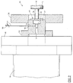
- FIG. 2 In a portion of the apparatus containing the shield gas inlet assembly, shown generally at 30, there is a cylinder 32 having at one end a cylindrical baffle channel 18 bored therein. The opposite end of cylinder 32 has a recess 36 adapted to receive plate 34, one side of plate 34 forming the base of recess 36, and the opposite side forming an end plate for baffle channel 18. Orifice 19 is realized as eight small apertures disposed in plate 34 to place recess 36 and baffle channel 18 in limited fluid communication.
- Sensor manifold 42 connects low pressure chamber 16 in sealed fluid communication with recess 36.
- the seal is established by ceramic seal 40 which resides in sensory manifold connector 38, a CF-63 conflat flange.
- a low pressure environment is thus maintained within recess 36, plate 34 forming a barrier separating the low pressure in recess 36 from a higher pressure environment in the baffle channel 18 on the other side of plate 32.
- Orifice 19 is dimensioned to allow a suitable flow of gas across the barrier.
- baffle channel 18 is sealably connected with process chamber 14 by a CF-35 conflat flange 44 and a CF-100 to CF-35 adaptor flange 46 for mounting assembly 30 directly on the walls of process chamber 14. This arrangement permits baffle channel 18 to be located almost within the volume of process chamber 14.
- Shield gas inlet 24 is a long hole bored from one side of cylinder 32 into the baffle channel 18.
- Capillary tubing 54 is used to connect a needle valve 58 to the shield gas inlet port 56.
- the shield gas flow can be obtained from the process gas inlet system (not shown).
- FIG. 3 there is shown a partially schematic test arrangement of a preferred embodiment of the invention which was used in the Examples given below. Internal detail not shown in FIG. 3 is the same as in FIG. 2, and the dimensions of the test embodiment are as given in Table 3. It is evident from Table 3 that the volume of the capillary tube and shield gas inlet are small in comparison with the volume of the baffle channel, the latter being approximately 20 times as large as the volume in the shield gas flow tubing and inlet combined.
- Process gas argon carrier gas in the tests herein, enters the system through flowmeter 81.
- Needle valve 86 is set to regulate the flow out of flowmeter 81 at 1000 sccm.
- the gas inlet system allows a small portion of the process gas to be used as the shield gas. This is diverted to the shield gas inlet port 56 through a T-connector 84 by setting flowmeter 82 to the desired shield flow with needle valve 58.
- process chamber 14 is a 2.5 liter vessel in which a desired internal pressure is provided by rotary vane pump 60, the action of which is regulated by throttle valve 62.
- a 100 Torr capacitance manometer 64 is mounted on process chamber 14.
- Sensor manifold 42 houses a quadropole sensor 95 having a closed ion source mounted thereon, and is pumped by a Leybold model TMP-50 66 turbomolecular pump discharging to a rotary vane pump 68.
- Ionization gauge 70 is used to monitor pressure within sensory manifold 42.
- FIG. 4 presents a typical response, but does not necessarily describe a particular test result herein.
- the process gas argon
- the process gas was set to a flow rate of 1000 sccm at process pressures to 25, 50, 76, and 98 Torr, with the flow rate of contaminant gas (nitrogen) held constant at 100 sccm.
- the time response was measured at shield gas flows of 10, 25, 50, 75, and 100 sccm in accordance with the following steps:
- the amount of shielding provided by the shield gas flow was determined by taking the ratio of the partial pressure of the contaminant detected by the mass spectrometer with the shield flow on to the partial pressure of the contaminant detected with the shield flow off. This was done at process pressures of 50, 76, and 98 Torr with shield gas flows set at 10, 25, and 50 sccm. The process flow (argon) was held constant at 1000 sccm, and the contaminant (nitrogen) set at 100 sccm. The shielding ratios measured are summarized in Table 5.
- FIG. 5 there is schematically shown an alternate embodiment of the invention.
- the baffle channel 118 is somewhat longer. From the equation given above, it will be evident that a greater protection for the orifice 119 can be achieved by lengthening the baffle channel, but at a cost in response time.
- an outlet 175 is provided, leading to an evacuation pump (not shown). It is desirable that the diameter of outlet be relatively large to increase flow conductance, and in practice an instantaneous shutoff valve (not shown) may be provided to close the outlet when it is not in use.
- the evacuation pump may be left in continuous operation, so that process gas 112 follows a relatively long path along baffle channel 118 between reaction chamber 114 and the outlet 175, encountering a relatively short counterflow of shield gas 122 at the mouth of outlet 175.
- This arrangement has the advantage that virtually no shield gas ever enters the reaction chamber 114, and the reaction occurring therein can proceed completely undisturbed by the monitoring process.
- the evacuation pump In a second mode of operation, the evacuation pump is left off, or the outlet 175 blocked by a switching device (not shown), so that it operates in the same manner as the first embodiment.
- the shield gas may optionally be cut off, the outlet 175 reopened and the evacuation pump started to quickly purge baffle channel 118 of gas that is representative of a previous state of the reaction in the reaction chamber 114.
- the contents of baffle channel 118 are then replaced by new process gas, representing a current state of the reaction. Purging the baffle channel thus avoids analytic error due to carry over in a subsequent monitoring operation.
Landscapes
- Chemical & Material Sciences (AREA)
- Analytical Chemistry (AREA)
- Physics & Mathematics (AREA)
- Health & Medical Sciences (AREA)
- Life Sciences & Earth Sciences (AREA)
- Biochemistry (AREA)
- General Health & Medical Sciences (AREA)
- General Physics & Mathematics (AREA)
- Immunology (AREA)
- Pathology (AREA)
- Sampling And Sample Adjustment (AREA)
Applications Claiming Priority (2)
| Application Number | Priority Date | Filing Date | Title |
|---|---|---|---|
| US08/007,840 US5318752A (en) | 1993-01-22 | 1993-01-22 | Method and apparatus for sampling a reactive atmosphere into a vacuum chamber of an analyzer |
| US7840 | 1993-01-22 |
Publications (2)
| Publication Number | Publication Date |
|---|---|
| EP0607908A2 true EP0607908A2 (de) | 1994-07-27 |
| EP0607908A3 EP0607908A3 (de) | 1996-03-06 |
Family
ID=21728390
Family Applications (1)
| Application Number | Title | Priority Date | Filing Date |
|---|---|---|---|
| EP94100609A Withdrawn EP0607908A3 (de) | 1993-01-22 | 1994-01-18 | Verfahren und Vorrichtung zur Einführung einer aus einer reaktiven Atmosphäre gewonnenen Probe in eine Vakuumkammer eines Analysators. |
Country Status (3)
| Country | Link |
|---|---|
| US (1) | US5318752A (de) |
| EP (1) | EP0607908A3 (de) |
| KR (1) | KR940018658A (de) |
Cited By (2)
| Publication number | Priority date | Publication date | Assignee | Title |
|---|---|---|---|---|
| EP0718613A1 (de) * | 1994-12-23 | 1996-06-26 | Balzers Aktiengesellschaft | Gasanalyse- oder Lecksuchverfahren und Geräte hierfür |
| DE102016109053A1 (de) | 2015-05-15 | 2016-11-17 | Micromass Uk Limited | Zusatzgaseinlass |
Families Citing this family (11)
| Publication number | Priority date | Publication date | Assignee | Title |
|---|---|---|---|---|
| US5698168A (en) * | 1995-11-01 | 1997-12-16 | Chorus Corporation | Unibody gas plasma source technology |
| DE29605650U1 (de) * | 1996-03-27 | 1996-07-25 | Balzers Prozess Systeme Vertriebs- und Service GmbH, 81245 München | Anordnung zum Verbinden eines Tiefdruckeinganges eines Gasanalysegerätes |
| US6590205B2 (en) * | 2000-08-10 | 2003-07-08 | Anelva Corporation | Ionization method for mass spectrometry and mass spectrometry apparatus |
| US20030020618A1 (en) * | 2001-04-13 | 2003-01-30 | Randy Hemmer | Methamphetamine and other illegal drug manufacture detector |
| US7211793B2 (en) * | 2004-11-09 | 2007-05-01 | Cummins, Inc | Mass spectrometry system and method |
| US8424367B2 (en) * | 2009-03-04 | 2013-04-23 | University Of South Carolina | Systems and methods for measurement of gas permeation through polymer films |
| US8635899B2 (en) | 2009-07-15 | 2014-01-28 | Rosemount Analytical Inc. | Flame safety system for in SITU process analyzer |
| US9627324B2 (en) * | 2009-11-17 | 2017-04-18 | Evatec Ag | Apparatus and method for processing a substrate |
| US9797849B2 (en) | 2013-03-29 | 2017-10-24 | Rosemount Analytical Inc. | Method of operation an in SITU process probe |
| GB201508328D0 (en) | 2015-05-15 | 2015-06-24 | Micromass Ltd | Auxiliary gas inlet |
| KR102133334B1 (ko) * | 2020-02-25 | 2020-07-14 | 영인에이스 주식회사 | 질량분석기 |
Family Cites Families (8)
| Publication number | Priority date | Publication date | Assignee | Title |
|---|---|---|---|---|
| US4023398A (en) * | 1975-03-03 | 1977-05-17 | John Barry French | Apparatus for analyzing trace components |
| US4135382A (en) * | 1978-01-23 | 1979-01-23 | Thermo-Lab Instruments, Inc. | Apparatus for developing a counterflow to clean a fluid conveying conduit of a gas analyzer |
| USRE33386E (en) * | 1983-01-14 | 1990-10-16 | Method and apparatus for sampling a plasma into a vacuum chamber | |
| US4718268A (en) * | 1985-06-04 | 1988-01-12 | British Aerospace Public Limited Company | Method and apparatus for detecting a contraband substance |
| US5009849A (en) * | 1984-12-14 | 1991-04-23 | Monsanto Company | Apparatus for carrying out catalyzed chemical reactions and for studying catalysis |
| US4935624A (en) * | 1987-09-30 | 1990-06-19 | Cornell Research Foundation, Inc. | Thermal-assisted electrospray interface (TAESI) for LC/MS |
| JP2675561B2 (ja) * | 1987-12-18 | 1997-11-12 | 株式会社日立製作所 | プラズマ微量元素分折装置 |
| US4970905A (en) * | 1989-05-25 | 1990-11-20 | University Of Utah | Apparatus and method for sampling |
-
1993
- 1993-01-22 US US08/007,840 patent/US5318752A/en not_active Expired - Lifetime
-
1994
- 1994-01-18 EP EP94100609A patent/EP0607908A3/de not_active Withdrawn
- 1994-01-21 KR KR1019940001116A patent/KR940018658A/ko not_active Withdrawn
Cited By (6)
| Publication number | Priority date | Publication date | Assignee | Title |
|---|---|---|---|---|
| EP0718613A1 (de) * | 1994-12-23 | 1996-06-26 | Balzers Aktiengesellschaft | Gasanalyse- oder Lecksuchverfahren und Geräte hierfür |
| US5756881A (en) * | 1994-12-23 | 1998-05-26 | Balzers Aktiengesellschaft | Gas analysis or leak detection process and device for same |
| DE102016109053A1 (de) | 2015-05-15 | 2016-11-17 | Micromass Uk Limited | Zusatzgaseinlass |
| GB2538870A (en) * | 2015-05-15 | 2016-11-30 | Micromass Ltd | Auxiliary gas inlet |
| GB2538870B (en) * | 2015-05-15 | 2019-12-04 | Micromass Ltd | Auxiliary gas inlet |
| DE102016109053B4 (de) | 2015-05-15 | 2023-05-04 | Micromass Uk Limited | Zusatzgaseinlass |
Also Published As
| Publication number | Publication date |
|---|---|
| EP0607908A3 (de) | 1996-03-06 |
| KR940018658A (ko) | 1994-08-18 |
| US5318752A (en) | 1994-06-07 |
Similar Documents
| Publication | Publication Date | Title |
|---|---|---|
| EP0607908A2 (de) | Verfahren und Vorrichtung zur Einführung einer aus einer reaktiven Atmosphäre gewonnenen Probe in eine Vakuumkammer eines Analysators | |
| US5485016A (en) | Atmospheric pressure ionization mass spectrometer | |
| US5142143A (en) | Method and apparatus for preconcentration for analysis purposes of trace constitutes in gases | |
| US6686594B2 (en) | On-line UV-Visible light halogen gas analyzer for semiconductor processing effluent monitoring | |
| US8237116B2 (en) | GC-MS analysis apparatus | |
| EP1668253B1 (de) | Erfassung von verunreinigungen in einem durch eine vakuumpumpe gepumpten fluid | |
| US11658019B2 (en) | IMR-MS reaction chamber | |
| Whitson Jr et al. | Temperature dependence of the quenching of vibrationally excited N2 by NO and H2O | |
| US20220048081A1 (en) | Endpoint Detection of Deposition Cleaning in a Pumping Line and a Processing Chamber | |
| CN112782264B (zh) | 一种用于密闭空间微量有害气体检测及校准的装置及方法 | |
| EP0559089B1 (de) | Reagenzgasdurchsatzregelung für einen, im chemischen Ionisationsmodus betriebenen Ionenfallenmassenspektrometer | |
| Blessing et al. | Recommended practice for process sampling for partial pressure analysis | |
| JP2001351569A (ja) | ガス測定用オンラインモニター装置 | |
| Tobin et al. | Gas phase composition in the low pressure chemical vapor deposition of silicon dioxide | |
| US7863055B2 (en) | Sampling system for introduction of high boiling point streams at low temperature | |
| JPH1012601A (ja) | Cvd装置及びcvd成膜方法 | |
| US7094614B2 (en) | In-situ monitoring of chemical vapor deposition process by mass spectrometry | |
| JP3299102B2 (ja) | 半導体特殊ガス用赤外線ガス分析計 | |
| CN1214528A (zh) | 一种质谱仪 | |
| US6518581B1 (en) | Apparatus for control of gas flow into a mass spectrometer using a series of small orifices | |
| US6310340B1 (en) | Arrangement for connecting a low-pressure inlet of a gas analyzer | |
| KR20060042741A (ko) | 상압 공정에 이용되는 가스 반응 분석 장치를 위한 샘플가스 공급 시스템 | |
| Grimsrud | Vacuum envelope for high pressure mass spectrometry applications | |
| JPH0955185A (ja) | 校正ガス系統を備えたマスフィルター型ガス分析計及びその操作方法 | |
| JPH10239280A (ja) | 質量分析方法及び試料ガス混合装置 |
Legal Events
| Date | Code | Title | Description |
|---|---|---|---|
| PUAI | Public reference made under article 153(3) epc to a published international application that has entered the european phase |
Free format text: ORIGINAL CODE: 0009012 |
|
| AK | Designated contracting states |
Kind code of ref document: A2 Designated state(s): DE FR GB IT NL |
|
| PUAL | Search report despatched |
Free format text: ORIGINAL CODE: 0009013 |
|
| AK | Designated contracting states |
Kind code of ref document: A3 Designated state(s): DE FR GB IT NL |
|
| 17P | Request for examination filed |
Effective date: 19960813 |
|
| 17Q | First examination report despatched |
Effective date: 19991026 |
|
| STAA | Information on the status of an ep patent application or granted ep patent |
Free format text: STATUS: THE APPLICATION IS DEEMED TO BE WITHDRAWN |
|
| 18D | Application deemed to be withdrawn |
Effective date: 20000506 |