EP0605315A1 - Dispositif d'actionnement à vérin de traction et rappel élastique - Google Patents
Dispositif d'actionnement à vérin de traction et rappel élastique Download PDFInfo
- Publication number
- EP0605315A1 EP0605315A1 EP93403181A EP93403181A EP0605315A1 EP 0605315 A1 EP0605315 A1 EP 0605315A1 EP 93403181 A EP93403181 A EP 93403181A EP 93403181 A EP93403181 A EP 93403181A EP 0605315 A1 EP0605315 A1 EP 0605315A1
- Authority
- EP
- European Patent Office
- Prior art keywords
- drive device
- motor
- movable
- flexible
- hauling
- Prior art date
- Legal status (The legal status is an assumption and is not a legal conclusion. Google has not performed a legal analysis and makes no representation as to the accuracy of the status listed.)
- Granted
Links
- 230000007246 mechanism Effects 0.000 claims abstract description 8
- 238000004873 anchoring Methods 0.000 claims abstract description 5
- 238000006073 displacement reaction Methods 0.000 claims abstract description 4
- 238000004804 winding Methods 0.000 claims description 4
- 229910003460 diamond Inorganic materials 0.000 claims description 2
- 239000010432 diamond Substances 0.000 claims description 2
- 239000002184 metal Substances 0.000 claims description 2
- 229910052751 metal Inorganic materials 0.000 claims description 2
- 239000006096 absorbing agent Substances 0.000 claims 1
- 230000035939 shock Effects 0.000 claims 1
- XEEYBQQBJWHFJM-UHFFFAOYSA-N Iron Chemical compound [Fe] XEEYBQQBJWHFJM-UHFFFAOYSA-N 0.000 description 2
- 230000005540 biological transmission Effects 0.000 description 2
- 239000003638 chemical reducing agent Substances 0.000 description 1
- 239000012530 fluid Substances 0.000 description 1
- 230000037431 insertion Effects 0.000 description 1
- 238000003780 insertion Methods 0.000 description 1
- 229910052742 iron Inorganic materials 0.000 description 1
- 230000006641 stabilisation Effects 0.000 description 1
- 230000000087 stabilizing effect Effects 0.000 description 1
Images

Classifications
-
- B—PERFORMING OPERATIONS; TRANSPORTING
- B66—HOISTING; LIFTING; HAULING
- B66F—HOISTING, LIFTING, HAULING OR PUSHING, NOT OTHERWISE PROVIDED FOR, e.g. DEVICES WHICH APPLY A LIFTING OR PUSHING FORCE DIRECTLY TO THE SURFACE OF A LOAD
- B66F19/00—Hoisting, lifting, hauling or pushing, not otherwise provided for
-
- B—PERFORMING OPERATIONS; TRANSPORTING
- B60—VEHICLES IN GENERAL
- B60N—SEATS SPECIALLY ADAPTED FOR VEHICLES; VEHICLE PASSENGER ACCOMMODATION NOT OTHERWISE PROVIDED FOR
- B60N2/00—Seats specially adapted for vehicles; Arrangement or mounting of seats in vehicles
- B60N2/90—Details or parts not otherwise provided for
- B60N2/919—Positioning and locking mechanisms
- B60N2/929—Positioning and locking mechanisms linear
-
- B—PERFORMING OPERATIONS; TRANSPORTING
- B66—HOISTING; LIFTING; HAULING
- B66F—HOISTING, LIFTING, HAULING OR PUSHING, NOT OTHERWISE PROVIDED FOR, e.g. DEVICES WHICH APPLY A LIFTING OR PUSHING FORCE DIRECTLY TO THE SURFACE OF A LOAD
- B66F3/00—Devices, e.g. jacks, adapted for uninterrupted lifting of loads
-
- B—PERFORMING OPERATIONS; TRANSPORTING
- B66—HOISTING; LIFTING; HAULING
- B66F—HOISTING, LIFTING, HAULING OR PUSHING, NOT OTHERWISE PROVIDED FOR, e.g. DEVICES WHICH APPLY A LIFTING OR PUSHING FORCE DIRECTLY TO THE SURFACE OF A LOAD
- B66F7/00—Lifting frames, e.g. for lifting vehicles; Platform lifts
- B66F7/06—Lifting frames, e.g. for lifting vehicles; Platform lifts with platforms supported by levers for vertical movement
- B66F7/0633—Mechanical arrangements not covered by the following subgroups
-
- Y—GENERAL TAGGING OF NEW TECHNOLOGICAL DEVELOPMENTS; GENERAL TAGGING OF CROSS-SECTIONAL TECHNOLOGIES SPANNING OVER SEVERAL SECTIONS OF THE IPC; TECHNICAL SUBJECTS COVERED BY FORMER USPC CROSS-REFERENCE ART COLLECTIONS [XRACs] AND DIGESTS
- Y10—TECHNICAL SUBJECTS COVERED BY FORMER USPC
- Y10T—TECHNICAL SUBJECTS COVERED BY FORMER US CLASSIFICATION
- Y10T74/00—Machine element or mechanism
- Y10T74/18—Mechanical movements
- Y10T74/18568—Reciprocating or oscillating to or from alternating rotary
- Y10T74/18832—Reciprocating or oscillating to or from alternating rotary including flexible drive connector [e.g., belt, chain, strand, etc.]
- Y10T74/18848—Reciprocating or oscillating to or from alternating rotary including flexible drive connector [e.g., belt, chain, strand, etc.] with pulley
-
- Y—GENERAL TAGGING OF NEW TECHNOLOGICAL DEVELOPMENTS; GENERAL TAGGING OF CROSS-SECTIONAL TECHNOLOGIES SPANNING OVER SEVERAL SECTIONS OF THE IPC; TECHNICAL SUBJECTS COVERED BY FORMER USPC CROSS-REFERENCE ART COLLECTIONS [XRACs] AND DIGESTS
- Y10—TECHNICAL SUBJECTS COVERED BY FORMER USPC
- Y10T—TECHNICAL SUBJECTS COVERED BY FORMER US CLASSIFICATION
- Y10T74/00—Machine element or mechanism
- Y10T74/18—Mechanical movements
- Y10T74/18888—Reciprocating to or from oscillating
- Y10T74/1892—Lever and slide
- Y10T74/18952—Lever and slide toggle transmissions
Definitions
- the invention relates to a drive device intended for the movement in space of a movable object relative to a fixed point.
- the drive mechanisms of this type can be used, in particular, to lift the head and foot elements of armchairs and beds, orient satellite dishes, remotely control inaccessible levers of any kind.
- the invention aims to conform a drive device for the uses mentioned, so that, in a very small footprint, the drive device has a very large displacement capacity and that the various components of the device are very simple configuration and assembly and a very low cost price.
- a drive device of the aforementioned type is essentially characterized, being arranged in accordance with the invention, in that it comprises a motor driving around its shaft a windable element pulling on a movable lifting element linked to a fixed point serving as anchoring to the flexible and sliding element, perpendicular to the axis of the hauling mechanism thus formed, in a tubular guide which shelters it and compressing a return spring ensuring the return in extension of the mobile element , so that this device works in tension and without buckling stress.
- reduction means are provided to increase the performance of the device; advantageously, the reduction means comprise at least one roller organized in hauling, and in practice several rollers organized in stepped hauling on which the rollable element rolls which can preferably be chosen from a metallic strip, a chain, a flexible rope, such as 'a piano string.
- the device in a very small footprint, in particular in height, allowing for example to incorporate it without difficulty into a bed frame, without parts or parts of parts protrude and are likely to injure a user.
- the movable element moved by the device To stabilize the movable element moved by the device and ensure that it remains parallel to a reference direction (in particular in the case of a lifting end of the bed), it is advantageous to also make the movable element either linked to a coaxial tube supporting pairs of opposite arms meshing mutually by their adjacent ends respectively and joined in an articulated manner at their other end to the two mutually movable parts under the action of the drive device, whereby said arms form at least one deformable diamond conferring a mutually parallel movement of the two parts.
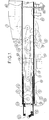
- a drive device for the movement in space of a moving part relative to a fixed point, comprises a motor 1 driving, around from its shaft 2, a windable element 4 pulling on a mobile lifting element 9 linked to a fixed point 22 serving to anchor the flexible element 4 and sliding, perpendicular to the axis of the hauling mechanism thus formed, in a tubular guide 15 inside which it is housed and compressing a return spring 10 ensuring the return in extension of the movable element 9 thus playing its role of jack.
- the flexible winding element 4 can be a metal strip; or else a chain formed of articulated elements with constant pitch, allowing its traction by a pinion replacing the winch 3, integral with the shaft 2, this in order to obtain a constant traction force; or even a flexible rope, for example a piano cord.
- the motor 1 is associated with gear reduction means which, advantageously, comprise at least one roller 5 organized in hauling.
- gear reduction means which, advantageously, comprise at least one roller 5 organized in hauling.
- the reduction of the mechanism can of course be increased by increasing the number of rollers, as shown by the rollers 5, 6, 7 and 8 in FIG. 1, and by increasing the number of winding turns or strands of the element. flexible 4, so as to constitute a layered haul.
- rollers of different diameters 5, 6, 7 and 8 are carried by the axes 11 and 13 inside the movable lifting element 9 and by the axes 12 and 14 inside the guide 15, which allows to eliminate the risks of friction of the successive strands or layers of the flexible element 4 on itself.
- Such an arrangement can be produced as a whole in a very flattened form as shown in FIG. 1.
- the flexible element 4 hooked to the anchoring point 22 secured to the base of the movable element 9 is wound on the first roller 8 of small diameter secured to the guide 15, located near the stop 30 of the spring reminder 10 and in all cases between this stop and the winch 3; the flexible element 4 then extends towards the second roller 7 of a greater diameter located between the anchoring point 22 and the larger roller 5 integral with the movable element 9, then winds on said roller 7 to then pass around a roller 6 of greater diameter, located on the guide 15 between the winch 3 and the roller 8; it then reaches the largest roller 5 to be wound on the latter, then is fixed on the winch 3.
- the five strands of this hauling are not limiting and the number of strands must be adapted according to the power of the engine and of the effort to develop.
- the axes 11, 12, 13 and 14 must be kept parallel and it is necessary to provide means preventing the rotation of the movable element 9 in its guide 15, for example by making the two members 9 and 15 in the form of polygonal sliding tubes or round fluted or keyed tubes, or tubes with oval sections.
- the motor 1 is of the electric type, for example extra-flat with permanent magnet, and provision is made an automatic engine stop system comprising extension limit switch 16 and retraction limit switch 17 actuable by a linkage 18 and an adjustable cleat 19 mounted thereon, this linkage 18 being driven parallel to the element of lifting 9 and connected to it by an elastic transmission 20.
- the limit switch 17 for the retracted position of the movable element 9 has the further characteristic of being controlled by an all-or-nothing magnetic trigger 21 which, being solicited by the linkage 18, pushes on a soft iron plate 22 pivotally mounted on an axis 23, abruptly takes it off from the permanent magnet 21 after having sufficiently stored energy a u level of the elastic transmission 20 and abruptly actuates the switch 17 which takes an abruptly open position; this mechanism is not necessary at the end of the extension stroke, the drive device developing at this time an effort approaching zero.
- the described electrical limit switch can also control and control the fluid supply to the solenoid valve of a braked pneumatic or braked hydraulic motor with electric brake, used as a variant of an electric motor.
- FIG. 2 shows the drive device in the form of a cover element ready to be mounted.
- the fixings on a fixed object and a removable object are carried out by means of a movable axis 24 and a removable axis 25 respectively, the latter being associated with an integrated overload damper, for example a spring 28 linked to the inner end 29 of the movable element 9 beyond the large diameter roller 5.
- An electrical connection cable 16 makes it possible to operate the device by remote control by means of the insertion of a reversing switch 27, selecting the direction of the running, the electrical energy being taken from the electrical sector or at the terminals of an accumulator or the like.
- the advantage of the device according to the invention is that it works in traction and therefore without buckling stress.
- a typical embodiment of a drive device of the type described above can be as follows: as a drive motor, a motor-reducer 1 with an extra-flat permanent magnet of the window lifter type is used developing, on its output shaft, a torque of 1 da.Nm winding the strip 4 on a winch 3 of a centimeter in diameter, which gives a pulling force of 100 daN multiplied by 5 due to reeving with five strands , or 500 m. in approximately.
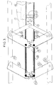
- FIG. 3 schematically shows a particular embodiment of the device of the invention arranged for the mutually parallel movement of two parts, in particular of the elongated type (for example bars).
- the mobile element 9 is connected at 40 to a coaxial outer tube 31 supporting pairs of opposite arms 32, 34, 33, 35, 36, 37 mutually meshing by their adjacent ends respectively and secured to articulated at their other end with two parts (for example elongated in the form of bars) 38, 39 mutually displaceable under the action of the drive device, whereby said arms form at least one deformable rhombus conferring a mutually parallel movement of two parts 38, 39.
- the limit switches 40, 41 to be located inside the guide tube 15.
- a functional limit switch 41 can be provided in the case of the extension which is arranged to detect the relaxation of the flexible element 4 and give the actuator a variable and automatic safety stroke.
- the lower part 38 is then a transverse bar or end cross member of a fixed frame of the bed while the part 39 is a transverse bar or cross member of the frame of the movable part of the bed which can be moved vertically by pivoting relative to the fixed frame.
- the drive device according to the invention is mounted in a floating manner while being fixed to the parts 38 and 39 by the above arms, and remains at substantially equal distance from the parts 38 and 39 during the mutual displacement of these. this.
Landscapes
- Engineering & Computer Science (AREA)
- Mechanical Engineering (AREA)
- Life Sciences & Earth Sciences (AREA)
- Geology (AREA)
- Structural Engineering (AREA)
- Aviation & Aerospace Engineering (AREA)
- Transportation (AREA)
- Transmission Devices (AREA)
- Toilet Supplies (AREA)
- Devices For Conveying Motion By Means Of Endless Flexible Members (AREA)
- Flexible Shafts (AREA)
- Invalid Beds And Related Equipment (AREA)
- Braking Arrangements (AREA)
- Gear-Shifting Mechanisms (AREA)
- Automotive Seat Belt Assembly (AREA)
- Control Of Throttle Valves Provided In The Intake System Or In The Exhaust System (AREA)
- Vehicle Body Suspensions (AREA)
- Orthopedics, Nursing, And Contraception (AREA)
- Portable Nailing Machines And Staplers (AREA)
Abstract
Description
- L'invention est relative à un dispositif d'entraînement destiné au déplacement dans l'espace d'un objet mobile par rapport à un point fixe. Les mécanismes d'entraînement de ce type peuvent servir, en particulier, à lever des éléments de tête et de pieds de fauteuils et de lits, orienter des antennes paraboliques, commander à distance des leviers inaccessibles de toute sorte.
- L'invention a pour but de conformer un dispositif d'entraînement pour les usages cités, de telle sorte que, sous un encombrement très réduit, le dispositif d'entraînement ait une capacité de déplacement très importante et que les différents éléments constitutifs du dispositif soient de configuration et de montage très simple et d'un prix de revient très bas.
- A ces fins, un dispositif d'entraînement du type précité se caractérise essentiellement, étant agencé conformément à l'invention, en ce qu'il comprend un moteur entraînant autour de son arbre un élément enroulable tirant sur un élément de levage mobile lié à un point fixe servant d'ancrage à l'élément souple et coulissant, perpendiculairement à l'axe du mécanisme de mouflage ainsi constitué, dans un guide tubulaire qui l'abrite et comprimant un ressort de rappel assurant le retour en extension de l'élément mobile, de sorte que ce dispositif travaille en traction et sans contrainte de flambage. De préférence, on prévoit des moyens de démultiplication pour augmenter les performances du dispositif ; avantageusement les moyens de démultiplication comprennent au moins un galet organisé en mouflage, et en pratique plusieurs galets organisés en mouflage étagé sur lequel roule l'élément enroulable qui peut de préférence être choisi parmi un feuillard métallique, une chaîne, un filin souple, tel qu'une corde à piano.
- Il est ainsi possible de constituer le dispositif sous un très faible encombrement, notamment en hauteur, permettant par exemple de l'incorporer sans difficulté dans une armature de lit, sans que des pièces ou parties de pièces fassent saillie et soient susceptibles de blesser un utilisateur.
- Pour stabiliser l'élément mobile déplacé par le dispositif et faire en sorte qu'il demeure parallèle à une direction de référence (cas notamment d'une extrémité relevable de lit), il est intéressant de faire en outre en sorte que l'élément mobile soit lié à une tube coaxial supportant des paires de bras opposés engrenant mutuellement par leurs extrémités adjacentes respectivement et solidarisés de façon articulée à leur autre extrémité aux deux pièces mutuellement déplaçables sous l'action du dispositif d'entraînement, ce grâce à quoi lesdits bras forment au moins un losange déformable conférant un déplacement mutuellement parallèle des deux pièces.
- L'invention sera mieux comprise à la lecture de la description détaillée qui suit de certains modes de réalisation préférés, donnés uniquement à titre d'exemples non limitatifs. Dans cette description, on se réfère aux dessins annexés sur lesquels :
- la figure 1 est une coupe longitudinale d'un mode de réalisation préféré d'un dispositif d'entraînement agencé conformément à l'invention ;
- la figure 2 est une vue de côté de l'ensemble du dispositif d'entraînement selon la figure 1 ; et
- la figure 3 est une vue de côté d'un mécanisme de stabilisation de l'élément mobile, susceptible d'être adjoint au dispositif des figures 1 et 2.
- En se référant tout d'abord aux figures 1 et 2, un dispositif d'entraînement constitué selon l'invention, pour le déplacement dans l'espace d'une pièce mobile par rapport à un point fixe, comprend un moteur 1 entraînant, autour de son arbre 2, un élément enroulable 4 tirant sur un élément de levage mobile 9 lié à un point fixe 22 servant d'ancrage à l'élément souple 4 et coulissant, perpendiculairement à l'axe du mécanisme de mouflage ainsi constitué, dans un guide tubulaire 15 à l'intérieur duquel il est logé et comprimant un ressort de rappel 10 assurant le retour en extension de l'élément mobile 9 jouant ainsi son rôle de vérin.
- L'élément enroulable souple 4 peut être un feuillard métallique ; ou bien encore une chaîne formée d'éléments articulés à pas constants, permettant sa traction par un pignon remplaçant le treuil 3, solidaire de l'arbre 2, ceci afin d'obtenir une force de traction constante ; ou bien encore un filin souple, par exemple une corde à piano.
- De préférence, on associe au moteur 1 des moyens de démultiplication qui, avantageusement, comprennent au moins un galet 5 organisé en mouflage. La démultiplication du mécanisme peut bien entendu être accrue en augmentant le nombre des galets, comme représenté par les galets 5, 6, 7 et 8 sur la figure 1, et en accroissant le nombre de tours d'enroulement ou de brins de l'élément souple 4, de façon à constituer un mouflage étagé.
- Les galets de diamètres différents 5, 6, 7 et 8 sont portés par les axes 11 et 13 à l'intérieur de l'élément de levage mobile 9 et par les axes 12 et 14 à l'intérieur du guide 15, ce qui permet d'éliminer les risques de frottement des brins ou couches successives de l'élément souple 4 sur lui-même. Un tel agencement peut être réalisé dans son ensemble sous une forme très aplatie comme montré à la figure 1.
- Ainsi, l'élément souple 4 accroché au point d'ancrage 22 solidaire de la base de l'élément mobile 9 s'enroule sur le premier galet 8 de faible diamètre solidaire du guide 15, situé à proximité de la butée 30 du ressort de rappel 10 et dans tous les cas entre cette butée et le treuil 3 ; l'élément souple 4 s'étend ensuite vers le deuxième galet 7 d'un diamètre supérieur situé entre le point d'ancrage 22 et le plus grand galet 5 solidaires de l'élément mobile 9, s'enroule alors sur ledit galet 7 pour passer ensuite autour d'un galet 6 de diamètre supérieur, situé sur le guide 15 entre le treuil 3 et le galet 8 ; il atteint ensuite le plus grand galet 5 pour s'enrouler sur ce dernier, puis est fixé sur le treuil 3. Les cinq brins de ce mouflage ne sont pas limitatifs et le nombre des brins doit être adapté en fonction de la puissance du moteur et de l'effort à développer. Les axes 11, 12, 13 et 14 doivent être maintenus parallèles et il convient de prévoir des moyens empêchant la rotation de l'élément mobile 9 dans son guide 15, par exemple en réalisant les deux organes 9 et 15 sous forme de tubes coulissants polygonaux ou de tubes ronds cannelés ou clavetés, ou encore de tubes à sections ovales.
- Selon un premier mode de réalisation avantageux en raison de sa simplicité de mise en oeuvre (par exemple pour commander le pivotement de parties mobiles de lits), le moteur 1 est du type électrique, par exemple extra-plat à aimant permanent, et on prévoit un système d'arrêt automatique du moteur comportant des interrupteurs de fin de course d'extension 16 et de rétraction 17 actionnables par une tringlerie 18 et un taquet réglable 19 monté sur celle-ci, cette tringlerie 18 étant entraînée parallèlement à l'élément de levage 9 et reliée à celui-ci par une transmission élastique 20. L'interrupteur de fin de course 17 de position rétractée de l'élément mobile 9 a pour autre caractéristique d'être piloté par un déclencheur magnétique 21 tout ou rien qui, étant sollicité par la tringlerie 18, pousse sur une plaque de fer doux 22 montée pivotante sur un axe 23, la décolle brutalement de l'aimant permanent 21 après avoir suffisamment emmagasiné d'énergie au niveau de la transmission élastique 20 et actionne brusquement l'interrupteur 17 qui prend une position brutalement ouverte; ce mécanisme n'est pas nécessaire en fin de course d'extension, le dispositif d'entraînement développant à ce moment-là un effort se rapprochant de zéro.
- Selon un autre mode de réalisation, le dispositif de fin de course électrique décrit peut aussi contrôler et piloter l'alimentation en fluide de l'électrovanne d'un moteur pneumatique freiné ou hydraulique freiné avec frein électrique, utilisé en variante d'un moteur électrique.
- La figure 2 montre le dispositif d'entraînement sous forme d'un élément capoté prêt à être monté. Les fixations sur un objet fixe et un objet amovible s'effectuent au moyen respectivement d'un axe mobile 24 et d'un axe amovible 25, ce dernier étant associé à un amortisseur intégré de surcharge, par exemple un ressort 28 lié à l'extrémité intérieure 29 de l'élément mobile 9 au-delà du galet de grand diamètre 5. Un câble électrique de liaison 16 permet de faire fonctionner le dispositif par télécommande grâce à l'insertion d'un interrupteur inverseur 27, sélectionnant le sens de la marche, l'énergie électrique étant prise sur le secteur électrique ou aux bornes d'un accumulateur ou analogue.
- L'intérêt du dispositif conforme à l'invention est qu'il travaille en traction et donc sans contrainte de flambage.
- Un exemple typique de réalisation d'un dispositif d'entraînement du type décrit ci-dessus peut être le suivant: en tant que moteur d'entraînement, on utilise un moto-réducteur 1 à aimant permanent extra-plat du type lève-vitre automobile développant, sur son arbre de sortie, un couple de 1 m.daN enroulant le feuillard 4 sur un treuil 3 d'un centimètre de diamètre, ce qui donne une force de traction de 100 daN multiplée par 5 en raison de mouflage à cinq brins, soit 500 m. daN environ.
- La figure 3 montre schématiquement un mode de réalisation particulier du dispositif de l'invention agencé en vue du déplacement mutuellement parallèle de deux pièces notamment de type allongé (par exemple des barres).
- Dans cet agencement l'élément mobile 9 est lié en 40 à un tube extérieur coaxial 31 supportant des paires de bras opposé 32, 34, 33, 35, 36, 37 engrenant mutuellement par leurs extrémités adjacentes respectivement et solidarisés de façon articulée à leur autre extrémité à deux pièces (par exemple allongées en forme de barres) 38, 39 mutuellement déplaçables sous l'action du dispositif d'entraînement, ce grâce à quoi lesdits bras forment au moins un losange déformable conférant un déplacement mutuellement parallèle de deux pièces 38, 39. Il est alors souhaitable que les interrupteurs de fin de course 40, 41 se trouvent à l'intérieur du tube guide 15. On peut prévoir un interrupteur de fin de course 41 fonctionnel dans le cas de l'extension qui est agencé pour détecter la détente de l'élément souple 4 et donner à l'actionneur une course de sécurité variable et automatique.
- Un tel agencement est notamment intéressant pour soulever une partie mobile de lit : la pièce inférieure 38 est alors une barre transversale ou traverse d'extrémité d'une armature fixe du lit tandis que la pièce 39 est une barre transversale ou traverse du cadre de la partie mobile du lit déplaçable verticalement par pivotement par rapport à l'armature fixe. Dans cette configuration le dispositif d'entraînement conforme à l'invention est monté de façon flottante en étant fixé aux pièces 38 et 39 par les susdits bras, et demeure à sensiblement égale distance des pièces 38 et 39 au cours du déplacement mutuel de celles-ci. Dans ce type précis d'application, on est assuré que la pièce 39 ne peut pas s'incliner par rapport à la pièce 38 même si la charge qu'elle supporte, en position relevée, n'est pas symétriquement répartie (par exemple personne allongée sur un côté du lit en partie relevé).
Claims (10)
- Dispositif d'entraînement destiné au déplacement dans l'espace d'une pièce mobile par rapport à un point fixe, caractérisé en ce qu'il comprend un moteur (1) entraînant autour de son arbre (2) un élément enroulable (4) tirant sur un élément de levage mobile (9) lié à un point fixe (22) servant d'ancrage à l'élément souple (4) et coulissant, perpendiculairement à l'axe du mécanisme de mouflage ainsi constitué, dans un guide tubulaire (15) qui l'abrite et comprimant un ressort de rappel (10) assurant le retour en extension de l'élément mobile (9), de sorte que ce dispositif travaille en traction et sans contrainte de flambage.
- Dispositif d'entraînement selon la revendication 1, caractérisé en ce qu'il comporte des moyens démultiplicateurs associés au moteur (1) pour le tirage de l'élément de levage mobile (10).
- Dispositif d'entraînement selon la revendication 2, caractérisé en ce que les moyens démultiplicateurs comprennent au moins un galet organisé en mouflage, notamment plusieurs galets (5 à 8) organisés en mouflage étagé, sur lequel roule ledit élément enroulable (4).
- Dispositif d'entraînement selon l'une quelconque des revendications 1 à 3, caractérisé en ce que l'élément enroulable souple est choisi parmi un feuillard (4) métallique, une chaîne, un filin souple, notamment une corde à piano.
- Dispositif d'entraînement selon la revendication 3 ou 4, caractérisé en ce que les galets (5 à 8) sont de diamètres différents et sont étagés sur des axes séparés (11, 13) à l'intérieur de l'élément de levage mobile (9 ; 12, 14) à l'intérieur du guide (15).
- Dispositif d'entraînement selon l'une quelconque des revendications 1 à 5, caractérisé en ce que le moteur (1) est choisi parmi un moteur électrique à aimant permanent extra-plat, un moteur pneumatique avec frein électrique piloté par des interrupteurs de fin de course (16, 17) électriques, ou un moteur hydraulique freiné qui est commandé par une électrovanne pilotée par des interrupteurs de fin de course (16, 17) électriques.
- Dispositif d'entraînement selon l'une quelconque des revendications 1 à 6, caractérisé en ce que l'élément mobile (9) est pourvu, pour sa fixation sur un objet, d'un axe amovible (25) assujetti à un amortisseur intégré (28), notamment un ressort (28) lié à l'extrémité (29) dudit élément mobile (9), servant de sécurité en cas de surcharge.
- Dispositif d'entraînement selon l'une quelconque des revendications 1 à 7, caractérisé en ce que l'élément mobile (9) est lié (en 40) à un tube extérieur coaxial (31) supportant des paires de bras opposés (32, 34, 33, 35, 36, 37) engrenant mutuellement par leurs extrémités adjacentes respectivement et solidarisés de façon articulée à leur autre extrémité à deux pièces (38, 39) mutuellement déplaçables sous l'action du dispositif d'entraînement, ce grâce à quoi lesdits bras forment au moins un losange déformable conférant un déplacement mutuellement parallèle des deux pièces (38, 39).
- Dispositif d'entraînement selon l'une quelconque des revendications 1 à 8, caractérisé en ce que des interrupteurs de fin de course (40, 41) se trouvent à l'intérieur du tube guide (15).
- Dispositif d'entraînement selon la revendication 9, caractérisé en ce qu'un interrupteur de fin de course intérieur d'extension (41) est agencé pour détecter la détente de l'élément souple (4) et donner à l'actionneur une course de sécurité variable et automatique.
Applications Claiming Priority (2)
| Application Number | Priority Date | Filing Date | Title |
|---|---|---|---|
| FR9215927A FR2699910B1 (fr) | 1992-12-30 | 1992-12-30 | Actionneur au vérin de traction à actionnement mécanique et rappel élastique. |
| FR9215927 | 1992-12-30 |
Publications (2)
| Publication Number | Publication Date |
|---|---|
| EP0605315A1 true EP0605315A1 (fr) | 1994-07-06 |
| EP0605315B1 EP0605315B1 (fr) | 1998-03-18 |
Family
ID=9437289
Family Applications (1)
| Application Number | Title | Priority Date | Filing Date |
|---|---|---|---|
| EP93403181A Expired - Lifetime EP0605315B1 (fr) | 1992-12-30 | 1993-12-27 | Dispositif d'actionnement à vérin de traction et rappel élastique |
Country Status (7)
| Country | Link |
|---|---|
| US (1) | US5528948A (fr) |
| EP (1) | EP0605315B1 (fr) |
| AT (1) | ATE164145T1 (fr) |
| DE (1) | DE69317538T2 (fr) |
| DK (1) | DK0605315T3 (fr) |
| ES (1) | ES2116423T3 (fr) |
| FR (1) | FR2699910B1 (fr) |
Cited By (1)
| Publication number | Priority date | Publication date | Assignee | Title |
|---|---|---|---|---|
| CN1083798C (zh) * | 1999-10-21 | 2002-05-01 | 刘民昌 | 一种牵引方法以及利用该方法制造的牵引机 |
Families Citing this family (31)
| Publication number | Priority date | Publication date | Assignee | Title |
|---|---|---|---|---|
| FR2727296B1 (fr) * | 1994-11-30 | 1997-01-31 | Dubuis | Agencement de securite pour l'entrainement motorise d'une partie mobile par rapport a une partie fixe et meuble qui en est equipe |
| US5830094A (en) * | 1995-11-03 | 1998-11-03 | Brown & Sharpe Manufacturing Company | Transmission for converting rotary motion into linear motion |
| US8303576B2 (en) * | 1998-02-24 | 2012-11-06 | Hansen Medical, Inc. | Interchangeable surgical instrument |
| US7758569B2 (en) * | 1998-02-24 | 2010-07-20 | Hansen Medical, Inc. | Interchangeable surgical instrument |
| US7901399B2 (en) * | 1998-02-24 | 2011-03-08 | Hansen Medical, Inc. | Interchangeable surgical instrument |
| US6170619B1 (en) | 1998-10-29 | 2001-01-09 | Honeywell Inc | Manual hand brake sensor for a railroad car |
| US6237722B1 (en) | 1998-12-10 | 2001-05-29 | Honeywell International Inc | Railroad handbrake “off” sensor |
| DE10031737C2 (de) * | 2000-06-29 | 2003-05-15 | Cimosys Ltd | Möbelantrieb zum Verstellen von Teilen eines Möbels relativ zueinander |
| NL1021732C1 (nl) * | 2002-06-21 | 2003-12-23 | Actiforce B V | Aandrijving voor het ten opzichte van elkaar verplaatsen van profieldelen onder tussenkomst van een flexibele materiaalstrook, in lengte verstelbare behuizing en meubel. |
| US8117931B2 (en) * | 2002-06-21 | 2012-02-21 | Actiforce International B.V. | Drive for displacing profile parts relative to each other via a flexible material strip, length-adjustable housing and article of furniture |
| US7331967B2 (en) * | 2002-09-09 | 2008-02-19 | Hansen Medical, Inc. | Surgical instrument coupling mechanism |
| US6981729B2 (en) * | 2004-04-26 | 2006-01-03 | Steury Brothers Llc | Drive assembly for a retractable top of a mobile housing |
| US9140025B2 (en) | 2013-03-14 | 2015-09-22 | Victor N. Barcroft | Long travel lift system |
| DE202013007106U1 (de) | 2013-08-09 | 2014-11-13 | Deon Group AG | Möbelantrieb |
| DE102013013199B4 (de) | 2013-04-18 | 2017-11-16 | Deon Group AG | Elektromotorischer Möbelantrieb |
| DE102014115039A1 (de) | 2014-07-18 | 2016-01-21 | Deon Group AG | Ausrückungsverfahren zur Ausrückung eines Möbelantriebs |
| DE102014115126A1 (de) | 2014-07-18 | 2016-01-21 | Deon Group AG | Elektromotorisch verstellbare Stützeinrichtung |
| DE102014115033A1 (de) | 2014-07-18 | 2016-01-21 | Deon Group AG | Elektromotorisch verstellbare Stützeinrichtung |
| EP3009051B1 (fr) | 2014-10-16 | 2018-11-07 | De Werth Group AG | Dispositif d'appui réglable à moteur électrique |
| DE102014115084A1 (de) | 2014-10-16 | 2016-04-21 | Deon Group AG | Möbelantrieb |
| DE102014115125A1 (de) | 2014-10-17 | 2016-05-19 | Deon Group AG | Elektromotorische Verstellvorrichtung |
| CN107257894B (zh) | 2015-02-23 | 2023-05-02 | 拓诺麦公司 | 高速杆型线性致动器 |
| DE102015106994A1 (de) | 2015-05-05 | 2016-11-10 | Deon Group AG | Elektromotorischer Möbelantrieb |
| CN106672871B (zh) * | 2017-03-15 | 2023-09-22 | 吴一平 | 一种即调式环境保护监测仪器承载结构 |
| CN110304572B (zh) * | 2019-07-31 | 2024-01-30 | 嘉兴市金腾机械股份有限公司 | 一种剪式千斤顶 |
| DE102021102440A1 (de) | 2020-02-05 | 2021-08-05 | De Werth Group Ag | Elektromotorische Verstellvorrichtung |
| DE102021119984A1 (de) | 2020-08-12 | 2022-02-17 | De Werth Group Ag | Elektromotorisch verstellbare Stützeinrichtung |
| DE102021108208A1 (de) | 2020-08-12 | 2022-02-17 | De Werth Group Ag | Elektromotorischer Möbelantrieb |
| US11571073B2 (en) | 2020-08-12 | 2023-02-07 | De Werth Group Ag | Electric motor adjustable support device |
| DE202021101715U1 (de) | 2020-08-17 | 2021-11-23 | De Werth Group Ag | Elektromotorischer Möbelantrieb |
| DE102021105230A1 (de) | 2021-03-04 | 2022-09-08 | De Werth Group Ag | Seilzugbetätigbares Möbelscharnier |
Citations (9)
| Publication number | Priority date | Publication date | Assignee | Title |
|---|---|---|---|---|
| DE51537C (de) * | G. BRISSLER in Berlin SW., Teltowerstrafse 37IV | Scheeren-Hebezeug mit Schraubenfedern | ||
| FR709875A (fr) * | 1931-01-23 | 1931-08-14 | Entpr Generale De Fond S Les P | Dispositif de levage |
| GB441280A (en) * | 1934-07-16 | 1936-01-16 | Jakob Marx | Improvements in lifting platforms, particularly for motor cars |
| DE920390C (de) * | 1940-09-04 | 1956-01-12 | Wilhelm Dr-Ing Ludowici | Scherenhubvorrichtung |
| US3765648A (en) * | 1971-09-07 | 1973-10-16 | R Rasmussen | Support apparatus |
| US4074892A (en) * | 1976-09-20 | 1978-02-21 | Vanguard, Inc. | Plural bearing and sheave assembly |
| EP0017914A1 (fr) * | 1979-04-12 | 1980-10-29 | Lupo, Marianne | Dispositif de levage pour installation dans un meuble pour téléviseur ou similaire |
| WO1992010422A1 (fr) * | 1990-12-04 | 1992-06-25 | WALLACE, Gregory, Stewart | Appareil elevateur |
| US5143507A (en) * | 1990-05-07 | 1992-09-01 | Vix Design Products, Inc. | Wheel handling apparatus |
Family Cites Families (8)
| Publication number | Priority date | Publication date | Assignee | Title |
|---|---|---|---|---|
| US1552833A (en) * | 1924-09-30 | 1925-09-08 | Schaffer & Budenberg G M B H | Valve |
| US2896908A (en) * | 1957-06-20 | 1959-07-28 | Robert H Stone | Fluorescent fixture hoist |
| US2884788A (en) * | 1957-09-17 | 1959-05-05 | Leeds & Northrup Co | Cable transmission systems for recorders |
| US2987937A (en) * | 1958-06-10 | 1961-06-13 | Eaton Mfg Co | Window operating mechanism |
| US4473010A (en) * | 1981-12-04 | 1984-09-25 | Stewart Engineering And Equipment Co., Inc. | Sensor traversing device |
| SE437188B (sv) * | 1984-05-07 | 1985-02-11 | Jan Ekman | Anordning av det slag som innefattar tva teleskopiskt samordnade organ |
| US5078364A (en) * | 1990-07-26 | 1992-01-07 | Sumner Manufacturing Co., Inc. | Carriage lock mechanism for portable cable hoist |
| US5221075A (en) * | 1990-11-06 | 1993-06-22 | Helmut Habicht | Safety device for a lifting apparatus |
-
1992
- 1992-12-30 FR FR9215927A patent/FR2699910B1/fr not_active Expired - Fee Related
-
1993
- 1993-12-23 US US08/172,239 patent/US5528948A/en not_active Expired - Fee Related
- 1993-12-27 EP EP93403181A patent/EP0605315B1/fr not_active Expired - Lifetime
- 1993-12-27 ES ES93403181T patent/ES2116423T3/es not_active Expired - Lifetime
- 1993-12-27 DK DK93403181T patent/DK0605315T3/da active
- 1993-12-27 DE DE69317538T patent/DE69317538T2/de not_active Expired - Fee Related
- 1993-12-27 AT AT93403181T patent/ATE164145T1/de not_active IP Right Cessation
Patent Citations (9)
| Publication number | Priority date | Publication date | Assignee | Title |
|---|---|---|---|---|
| DE51537C (de) * | G. BRISSLER in Berlin SW., Teltowerstrafse 37IV | Scheeren-Hebezeug mit Schraubenfedern | ||
| FR709875A (fr) * | 1931-01-23 | 1931-08-14 | Entpr Generale De Fond S Les P | Dispositif de levage |
| GB441280A (en) * | 1934-07-16 | 1936-01-16 | Jakob Marx | Improvements in lifting platforms, particularly for motor cars |
| DE920390C (de) * | 1940-09-04 | 1956-01-12 | Wilhelm Dr-Ing Ludowici | Scherenhubvorrichtung |
| US3765648A (en) * | 1971-09-07 | 1973-10-16 | R Rasmussen | Support apparatus |
| US4074892A (en) * | 1976-09-20 | 1978-02-21 | Vanguard, Inc. | Plural bearing and sheave assembly |
| EP0017914A1 (fr) * | 1979-04-12 | 1980-10-29 | Lupo, Marianne | Dispositif de levage pour installation dans un meuble pour téléviseur ou similaire |
| US5143507A (en) * | 1990-05-07 | 1992-09-01 | Vix Design Products, Inc. | Wheel handling apparatus |
| WO1992010422A1 (fr) * | 1990-12-04 | 1992-06-25 | WALLACE, Gregory, Stewart | Appareil elevateur |
Cited By (1)
| Publication number | Priority date | Publication date | Assignee | Title |
|---|---|---|---|---|
| CN1083798C (zh) * | 1999-10-21 | 2002-05-01 | 刘民昌 | 一种牵引方法以及利用该方法制造的牵引机 |
Also Published As
| Publication number | Publication date |
|---|---|
| DE69317538T2 (de) | 1998-11-19 |
| DE69317538D1 (de) | 1998-04-23 |
| US5528948A (en) | 1996-06-25 |
| FR2699910A1 (fr) | 1994-07-01 |
| EP0605315B1 (fr) | 1998-03-18 |
| FR2699910B1 (fr) | 1998-08-28 |
| ATE164145T1 (de) | 1998-04-15 |
| DK0605315T3 (da) | 1998-12-21 |
| ES2116423T3 (es) | 1998-07-16 |
Similar Documents
| Publication | Publication Date | Title |
|---|---|---|
| EP0605315B1 (fr) | Dispositif d'actionnement à vérin de traction et rappel élastique | |
| FR2508090A1 (fr) | Dispositif d'entrainement de fil pour moyen de reglage de fenetre | |
| US6668902B2 (en) | Sunshade apparatus for automobile | |
| FR2563203A1 (fr) | Treuil | |
| CH651257A5 (fr) | Dispositif de levage, notamment pour handicapes, sur vehicules. | |
| EP0015857B1 (fr) | Dispositif de motorisation de l'ouverture et du verrouillage d'un portail | |
| EP0751278B1 (fr) | Volet roulant motorisé | |
| WO2001061139A1 (fr) | Volet roulant motorise equipe de moyens d'arret automatique | |
| FR2827266A1 (fr) | Dispositif de couplage entre portes de cabine et portes palieres d'un ascenseur, actionne par un moteur independant du moteur d'entrainement des portes | |
| FR2669610A1 (fr) | Dispositif constitutif d'un ruban metallique sans fin entourant une ou plusieurs chaines de roulement. | |
| FR2852374A1 (fr) | Dispositif de transfert a verin pour le deplacement reversible en translation horizontale ou inclinee d'un objet | |
| FR2704257A1 (fr) | Store à enrouleur motorisé. | |
| FR2778375A1 (fr) | Dispositif de manoeuvre d'un embrayage | |
| EP1420980B1 (fr) | Procede de commande de rambardes laterales d'un elevateur d'un vehicule et dispositif le mettant en oeuvre | |
| EP0417270B1 (fr) | Dispositif d'ecran a enroulement | |
| FR2552823A1 (fr) | Demarreur pour moteur a combustion interne | |
| EP0477068B1 (fr) | Système de désenfumage pour façades de bâtiment | |
| FR2895777A1 (fr) | Dispositif de transmission de mouvement et commande de frein de stationnement pour vehicule automobile equipe d'un tel dispositif | |
| FR2897095A3 (fr) | Dispositif d'enroulement pour store venitien | |
| FR2761654A1 (fr) | Dispositif de commande a lien souple et a rattrapage de jeu | |
| FR2655634A1 (fr) | Verin a lanterne a tiges creuses telescopiques et son utilisation. | |
| FR2832970A1 (fr) | Dispositif de commande electrrique d'un frein de stationnement et/ou de secours | |
| FR2522081A1 (fr) | Verin moufle a double effet utilisable notamment pour commander les mouvements de fermeture et d'ouverture d'une porte coulissante ou basculante | |
| FR2800121A1 (fr) | Dispositif de manoeuvre pour volet roulant, store et similaire, a commande par manivelle comportant un systeme limiteur de couple | |
| CA2457875C (fr) | Treuil motorise |
Legal Events
| Date | Code | Title | Description |
|---|---|---|---|
| PUAI | Public reference made under article 153(3) epc to a published international application that has entered the european phase |
Free format text: ORIGINAL CODE: 0009012 |
|
| 17P | Request for examination filed |
Effective date: 19931230 |
|
| AK | Designated contracting states |
Kind code of ref document: A1 Designated state(s): AT BE CH DE DK ES GB IT LI NL SE |
|
| 17Q | First examination report despatched |
Effective date: 19951026 |
|
| 111L | Licence recorded |
Free format text: 960305 0100 DUBUIS, SOCIETE ANONYME |
|
| GRAG | Despatch of communication of intention to grant |
Free format text: ORIGINAL CODE: EPIDOS AGRA |
|
| GRAG | Despatch of communication of intention to grant |
Free format text: ORIGINAL CODE: EPIDOS AGRA |
|
| GRAH | Despatch of communication of intention to grant a patent |
Free format text: ORIGINAL CODE: EPIDOS IGRA |
|
| GRAH | Despatch of communication of intention to grant a patent |
Free format text: ORIGINAL CODE: EPIDOS IGRA |
|
| GRAA | (expected) grant |
Free format text: ORIGINAL CODE: 0009210 |
|
| REG | Reference to a national code |
Ref country code: CH Ref legal event code: PLI Owner name: DE GELIS, CHRISTIAN TRANSFER- DUBUIS, SOCIETE ANON |
|
| AK | Designated contracting states |
Kind code of ref document: B1 Designated state(s): AT BE CH DE DK ES GB IT LI NL SE |
|
| REF | Corresponds to: |
Ref document number: 164145 Country of ref document: AT Date of ref document: 19980415 Kind code of ref document: T |
|
| REG | Reference to a national code |
Ref country code: CH Ref legal event code: EP |
|
| REF | Corresponds to: |
Ref document number: 69317538 Country of ref document: DE Date of ref document: 19980423 |
|
| ITF | It: translation for a ep patent filed |
Owner name: BARZANO' E ZANARDO MILANO S.P.A. |
|
| REG | Reference to a national code |
Ref country code: CH Ref legal event code: NV Representative=s name: ISLER & PEDRAZZINI AG |
|
| GBT | Gb: translation of ep patent filed (gb section 77(6)(a)/1977) |
Effective date: 19980608 |
|
| REG | Reference to a national code |
Ref country code: ES Ref legal event code: FG2A Ref document number: 2116423 Country of ref document: ES Kind code of ref document: T3 |
|
| REG | Reference to a national code |
Ref country code: DK Ref legal event code: T3 |
|
| PLBE | No opposition filed within time limit |
Free format text: ORIGINAL CODE: 0009261 |
|
| STAA | Information on the status of an ep patent application or granted ep patent |
Free format text: STATUS: NO OPPOSITION FILED WITHIN TIME LIMIT |
|
| 26N | No opposition filed | ||
| REG | Reference to a national code |
Ref country code: CH Ref legal event code: PUE Owner name: DE GELIS, CHRISTIAN TRANSFER- LEGGETT & PLATT, INC |
|
| PGFP | Annual fee paid to national office [announced via postgrant information from national office to epo] |
Ref country code: DK Payment date: 20000919 Year of fee payment: 8 |
|
| PGFP | Annual fee paid to national office [announced via postgrant information from national office to epo] |
Ref country code: NL Payment date: 20000929 Year of fee payment: 8 |
|
| PGFP | Annual fee paid to national office [announced via postgrant information from national office to epo] |
Ref country code: AT Payment date: 20001103 Year of fee payment: 8 |
|
| PGFP | Annual fee paid to national office [announced via postgrant information from national office to epo] |
Ref country code: GB Payment date: 20001107 Year of fee payment: 8 |
|
| PGFP | Annual fee paid to national office [announced via postgrant information from national office to epo] |
Ref country code: SE Payment date: 20001201 Year of fee payment: 8 |
|
| PGFP | Annual fee paid to national office [announced via postgrant information from national office to epo] |
Ref country code: CH Payment date: 20010103 Year of fee payment: 8 |
|
| PGFP | Annual fee paid to national office [announced via postgrant information from national office to epo] |
Ref country code: BE Payment date: 20010118 Year of fee payment: 8 |
|
| NLS | Nl: assignments of ep-patents |
Owner name: LEGGETT & PLATT, INCORPORATED |
|
| PG25 | Lapsed in a contracting state [announced via postgrant information from national office to epo] |
Ref country code: GB Free format text: LAPSE BECAUSE OF NON-PAYMENT OF DUE FEES Effective date: 20011227 Ref country code: DK Free format text: LAPSE BECAUSE OF NON-PAYMENT OF DUE FEES Effective date: 20011227 Ref country code: AT Free format text: LAPSE BECAUSE OF NON-PAYMENT OF DUE FEES Effective date: 20011227 |
|
| PG25 | Lapsed in a contracting state [announced via postgrant information from national office to epo] |
Ref country code: SE Free format text: LAPSE BECAUSE OF NON-PAYMENT OF DUE FEES Effective date: 20011228 |
|
| PG25 | Lapsed in a contracting state [announced via postgrant information from national office to epo] |
Ref country code: LI Free format text: LAPSE BECAUSE OF NON-PAYMENT OF DUE FEES Effective date: 20011231 Ref country code: CH Free format text: LAPSE BECAUSE OF NON-PAYMENT OF DUE FEES Effective date: 20011231 Ref country code: BE Free format text: LAPSE BECAUSE OF NON-PAYMENT OF DUE FEES Effective date: 20011231 |
|
| REG | Reference to a national code |
Ref country code: GB Ref legal event code: IF02 |
|
| BERE | Be: lapsed |
Owner name: LEGGETT & PLATT INC. Effective date: 20011231 |
|
| PG25 | Lapsed in a contracting state [announced via postgrant information from national office to epo] |
Ref country code: NL Free format text: LAPSE BECAUSE OF NON-PAYMENT OF DUE FEES Effective date: 20020701 |
|
| EUG | Se: european patent has lapsed |
Ref document number: 93403181.6 |
|
| GBPC | Gb: european patent ceased through non-payment of renewal fee |
Effective date: 20011227 |
|
| REG | Reference to a national code |
Ref country code: CH Ref legal event code: PL |
|
| NLV4 | Nl: lapsed or anulled due to non-payment of the annual fee |
Effective date: 20020701 |
|
| REG | Reference to a national code |
Ref country code: DK Ref legal event code: EBP |
|
| PGFP | Annual fee paid to national office [announced via postgrant information from national office to epo] |
Ref country code: ES Payment date: 20030130 Year of fee payment: 10 |
|
| PG25 | Lapsed in a contracting state [announced via postgrant information from national office to epo] |
Ref country code: ES Free format text: LAPSE BECAUSE OF NON-PAYMENT OF DUE FEES Effective date: 20031229 |
|
| REG | Reference to a national code |
Ref country code: ES Ref legal event code: FD2A Effective date: 20031229 |
|
| PG25 | Lapsed in a contracting state [announced via postgrant information from national office to epo] |
Ref country code: IT Free format text: LAPSE BECAUSE OF NON-PAYMENT OF DUE FEES;WARNING: LAPSES OF ITALIAN PATENTS WITH EFFECTIVE DATE BEFORE 2007 MAY HAVE OCCURRED AT ANY TIME BEFORE 2007. THE CORRECT EFFECTIVE DATE MAY BE DIFFERENT FROM THE ONE RECORDED. Effective date: 20051227 |
|
| PGFP | Annual fee paid to national office [announced via postgrant information from national office to epo] |
Ref country code: DE Payment date: 20051228 Year of fee payment: 13 |
|
| PG25 | Lapsed in a contracting state [announced via postgrant information from national office to epo] |
Ref country code: DE Free format text: LAPSE BECAUSE OF NON-PAYMENT OF DUE FEES Effective date: 20070703 |