EP0605299B1 - Méthode de réglage d'un procédé de pulvérisation cathodique réactive - Google Patents
Méthode de réglage d'un procédé de pulvérisation cathodique réactive Download PDFInfo
- Publication number
- EP0605299B1 EP0605299B1 EP93403153A EP93403153A EP0605299B1 EP 0605299 B1 EP0605299 B1 EP 0605299B1 EP 93403153 A EP93403153 A EP 93403153A EP 93403153 A EP93403153 A EP 93403153A EP 0605299 B1 EP0605299 B1 EP 0605299B1
- Authority
- EP
- European Patent Office
- Prior art keywords
- target
- frequency
- reactive
- metalloid
- deposition
- Prior art date
- Legal status (The legal status is an assumption and is not a legal conclusion. Google has not performed a legal analysis and makes no representation as to the accuracy of the status listed.)
- Expired - Lifetime
Links
Images


Classifications
-
- C—CHEMISTRY; METALLURGY
- C23—COATING METALLIC MATERIAL; COATING MATERIAL WITH METALLIC MATERIAL; CHEMICAL SURFACE TREATMENT; DIFFUSION TREATMENT OF METALLIC MATERIAL; COATING BY VACUUM EVAPORATION, BY SPUTTERING, BY ION IMPLANTATION OR BY CHEMICAL VAPOUR DEPOSITION, IN GENERAL; INHIBITING CORROSION OF METALLIC MATERIAL OR INCRUSTATION IN GENERAL
- C23C—COATING METALLIC MATERIAL; COATING MATERIAL WITH METALLIC MATERIAL; SURFACE TREATMENT OF METALLIC MATERIAL BY DIFFUSION INTO THE SURFACE, BY CHEMICAL CONVERSION OR SUBSTITUTION; COATING BY VACUUM EVAPORATION, BY SPUTTERING, BY ION IMPLANTATION OR BY CHEMICAL VAPOUR DEPOSITION, IN GENERAL
- C23C14/00—Coating by vacuum evaporation, by sputtering or by ion implantation of the coating forming material
- C23C14/22—Coating by vacuum evaporation, by sputtering or by ion implantation of the coating forming material characterised by the process of coating
- C23C14/54—Controlling or regulating the coating process
-
- C—CHEMISTRY; METALLURGY
- C23—COATING METALLIC MATERIAL; COATING MATERIAL WITH METALLIC MATERIAL; CHEMICAL SURFACE TREATMENT; DIFFUSION TREATMENT OF METALLIC MATERIAL; COATING BY VACUUM EVAPORATION, BY SPUTTERING, BY ION IMPLANTATION OR BY CHEMICAL VAPOUR DEPOSITION, IN GENERAL; INHIBITING CORROSION OF METALLIC MATERIAL OR INCRUSTATION IN GENERAL
- C23C—COATING METALLIC MATERIAL; COATING MATERIAL WITH METALLIC MATERIAL; SURFACE TREATMENT OF METALLIC MATERIAL BY DIFFUSION INTO THE SURFACE, BY CHEMICAL CONVERSION OR SUBSTITUTION; COATING BY VACUUM EVAPORATION, BY SPUTTERING, BY ION IMPLANTATION OR BY CHEMICAL VAPOUR DEPOSITION, IN GENERAL
- C23C14/00—Coating by vacuum evaporation, by sputtering or by ion implantation of the coating forming material
- C23C14/0021—Reactive sputtering or evaporation
- C23C14/0036—Reactive sputtering
Definitions
- the present invention produced by Messrs Bruno STAUDER, Claude FRANTZ, Alain BILLARD and Philippe PIGEAT from the Laboratory of Science and Engineering of Surfaces (LSGS) - URA CNRS 1402 - autoimmune des Mines de NANCY (INPL), and Messrs Frédéric PERRY and opposition HENRION of the Laboratory of Physics of Ionized Environments (LPMI) - URA CNRS 835 - Faculty of Sciences - University of NANCY I, relates to a process which, by promoting the stabilization of the physical process of development, makes it possible to control the metalloid concentration of a physical deposition in reactive vapor phase using a cold plasma spraying a target.
- Processes of physical deposition in reactive vapor phase of the type recalled above are known, among which, by way of example, reactive magnetron sputtering in direct current or in radiofrequency, of a metallic or semiconductor target in the presence of '' a reactive gas (O 2 , N 2 , CH 4 , B 2 H 6 , SH 2 ...), vector of the metalloid element.
- the plasma gas responsible for sputtering the target is a rare gas, for example argon.
- the alloys capable of being synthesized are therefore based on a metal or a semiconductor enriched in metalloid (O, N, C, B, S).
- the stoichiometric compounds they may be oxides, nitrides, carbides, borides or sulfides. These alloys or compounds can be deposited on semiconductor or insulating metal substrates.
- the sputtering of a metallic or semi-conductive target is said to be reactive if it occurs in the presence of a chemically active gas with respect to the vapor emitted by this target.
- a reactive gas is introduced into the reactor, a fraction of this gas interacts with the various receptor surfaces (reactor walls, substrate, target), the possibly excess fraction being evacuated by the pumping group.
- the main difficulty which arises in reactive spraying conditions is the maintenance of a stable regime which makes it possible to control the metalloid composition of the deposit or its stoichiometry when it is a compound.
- experience as well as calculation based on recent reactive magnetron sputtering models show that it corresponds to a non-linear phenomenon which results in a hysteresis effect appearing on the curves which bind to the gas flow.
- reagent D R introduced into the reactor, the partial pressure P R of reactive gas, the concentration C Me in metalloid of the deposit, the speed V D of deposit, and the electrical characteristics of the discharge (target current and target voltage for continuous discharge or autopolarization voltage for radiofrequency discharge).
- FIGS. 1, 2 and 3 represent respectively as a function of the flow rate D R , the quantities P R , C Me and V D in the processes of the state of the art.
- the transitions RPE ⁇ RPC and RPC ⁇ RPE which occur respectively at critical flow rates (DR) A and (DR) C are unstable and result in a runaway effect which forces the operating point of the reactor to go from A to B or from C to D depending on whether the flow rate of reactive gas increases or decreases.
- the parts AB and CD of the curves thus define a hysteresis domain which is all the more wide and abrupt the greater the difference between the respective sputtering rates of the target in its elementary state and in its contaminated state.
- Such a control means has, in the best of cases, a response time of a few tenths of a second which, if suitable for the preparation of certain compounds, often turns out to be much too long, for example in the case of alumina Al 2 O 3 : in fact, molecular oxygen can react with the aluminum target by a very rapid chemisorption mechanism since it only takes a chemisorbed monolayer for a few milliseconds to form.
- the present invention aims to overcome these drawbacks.
- the subject of the invention is a method which promotes the stabilization of the physical deposition process and thus makes it possible to control the metalloid concentration of a deposit on a substrate produced by physical means in reactive vapor phase using '' a target sputtering cold plasma, characterized in that the instantaneous power applied to the target is cyclically reduced and increased at low frequency by variation of the applied voltage so as, alternatively, to cause a reaction between the target and the reactive gas, and spray the product of said reaction.
- the above reduction may go as far as a cancellation.
- the aforementioned increase is the consequence of an electrical pulse, the shape and amplitude of which can be complex.
- by low frequency is meant a frequency such that it allows to obtain the aforementioned reaction-spray cycle.
- the invention will be distinguished from the methods for cutting off micro-arcs capable of striking on the less eroded areas of the target (in the case of a supply by a negative DC voltage) at the locations where the appearance of 'A dielectric reaction product is most likely, these methods of cutting micro-arcs operating for periods much shorter than those of the invention and generally of the order of a microsecond.
- the frequency of this reduction in power is preferably between 0.1 and 1000 Hz and the duration of this reduction is preferably between 100 / f and 800 / f milliseconds, where f is this frequency.
- the frequency can be between 1 and 100 Hz and the duration of the power reductions between 1 millisecond and 800 milliseconds.
- the invention therefore essentially consists in carrying out a real-time self-control of the chemical reaction liable to take place on the surface of the target and thereby of the flow of vapor coming from the target, thanks to the superposition of '' Low frequency electrical pulses or oscillations at the target supply voltage (DC voltage, voltage radio frequency or superposition of the two).
- DC voltage, voltage radio frequency or superposition of the two DC voltage, voltage radio frequency or superposition of the two.
- These electrical pulses or oscillations of suitable shape, amplitude, duration and frequency must produce an extinction of the plasma or a notable reduction in the instantaneous power applied to the target for a period compatible with the diffusion rates and the reaction times of the metalloid species of the plasma with the different receiving surfaces of the reactor (target, substrate, walls). They must thus allow the controlled formation of a very thin reaction product on the surface of the target and ensure its spraying during the next phase when the plasma is ignited.
- the proposed method (if it extinguishes the plasma) makes it possible to cut the aforementioned micro-arcs. It should be noted, however, that for highly insulating dielectric reaction products, an arc-breaking system operating in a known microsecond manner is preferable in the case of direct current spraying.
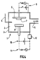
- FIG. 4 shows a reactor 1 formed by an enclosure 2, delimited by walls 3.
- a conduit 4 allows the introduction into enclosure 2 of a reactive gas or gas mixture as well as a plasma gas , and a conduit 5 connects the enclosure 2 to a pumping unit, not shown, ensuring that the necessary vacuum is obtained.
- a substrate holder 6 is arranged so as to receive a substrate 7 facing a target 8.
- the substrate holder 6 can be connected to generators 9, so as to ensure its polarization, either continuously or alternating radio frequency.
- the target 8 is produced in the metal or the semiconductor which it is desired to deposit in the form of an alloy or a compound on the substrate 7.
- the target 8 is supplied either with direct current by a generator 10 or with current alternating radio frequency by a generator 11.
- a device 12 making it possible to superimpose on the negative direct voltage delivered by the generator 10 or on the radio frequency voltage delivered by the generator 11 or on a superposition of these two voltages, electrical pulses or oscillations. low frequency.
- This device of any suitable electrical and / or magnetic type, makes it possible either to cut the power supply, or to reduce its instantaneous power.
- the device described above was used in the context of a reactive magnetron sputtering of targets made respectively of aluminum and zirconium with a diameter of 51 mm.
- the applied power was 260 watts and the target-substrate distance 80 mm.
- the target was supplied by a negative DC voltage, on which were superimposed pulses of frequency 50 Hertz, creating an extinction of the plasma for 5 milliseconds.
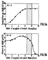
- FIG. 5a shows the composition of the Al-O deposit as an atonic percentage of oxygen in the case of an aluminum target as a function of the flow rate of oxygen introduced via line 4.
- the argon flow and the total pressure were 45 N.cm 3 / min and 0.8-1Pa respectively.
- FIG. 5b represents the deposition speed as a function of this same flow rate.
- Figures 6a and 6b are similar to Figures 5a and 5b in the case of a zirconium target.
- the argon flow and the total pressure were then respectively 36 N.cm 3 / min and 0.3-0.4 Pa.
Landscapes
- Chemical & Material Sciences (AREA)
- Chemical Kinetics & Catalysis (AREA)
- Engineering & Computer Science (AREA)
- Materials Engineering (AREA)
- Mechanical Engineering (AREA)
- Metallurgy (AREA)
- Organic Chemistry (AREA)
- Physical Vapour Deposition (AREA)
Description
- La présente invention, réalisée par Messieurs Bruno STAUDER, Claude FRANTZ, Alain BILLARD et Philippe PIGEAT du Laboratoire de Science et Génie des Surfaces (LSGS) - URA CNRS 1402 - Ecole des Mines de NANCY (I.N.P.L.), et Messieurs Frédéric PERRY et Gérard HENRION du Laboratoire de Physique des Milieux Ionisés (LPMI) - URA CNRS 835 - Faculté des Sciences - Université de NANCY I, concerne un procédé qui, en favorisant la stabilisation du processus physique d'élaboration, permet de contrôler la concentration en métalloïde d'un dépôt réalisé par voie physique en phase vapeur réactive à l'aide d'un plasma froid de pulvérisation d'une cible.
- On connait des procédés de dépôt physique en phase vapeur réactive du type rappelé ci-dessus, parmi lesquels, à titre d'exemple, la pulvérisation magnétron réactive en courant continu ou en radiofréquence, d'une cible métallique ou semi-conductrice en présence d'un gaz réactif (O2,N2,CH4,B2H6,SH2 ...), vecteur de l'élément métalloïde. Le gaz plasmagène responsable de la pulvérisation de la cible est un gaz rare, par exemple l'argon. Les alliages susceptibles d'être synthétisés sont donc à base d'un métal ou d'un semi-conducteur enrichi en métalloïde (O,N,C,B,S). Quant aux composés stoechiométriques, il peut s'agir d'oxydes, de nitrures, de carbures, de borures ou de sulfures. Ces alliages ou composés peuvent être déposés sur des substrats métalliques semi-conducteurs ou isolants.
- On sait que la pulvérisation d'une cible métallique ou semi-conductrice est dite réactive si elle intervient en présence d'un gaz chimiquement actif vis-à-vis de la vapeur émise par cette cible. Lorsqu'en présence d'une décharge électrique créant un plasma, on introduit un gaz réactif dans le réacteur, une fraction de ce gaz interagit avec les différentes surfaces réceptrices (parois du réacteur, substrat, cible), la fraction éventuellement excédentaire étant évacuée par le groupe de pompage.
- Ceci implique que la pression partielle PR de gaz réactif est inférieure à celle qui s'établirait en l'absence de décharge et que les caractéristiques électriques de la cible émettrice sont affectées à la fois par la participation croissante des espèces réactives à sa pulvérisation, par la modification éventuelle de la nature chimique de sa surface, et par un changement des conditions d'excitation et d'ionisation du gaz plasmagène.
- La difficulté principale qui survient en condition de pulvérisation réactive est le maintien d'un régime stable permettant de contrôler la composition en métalloïde du dépôt ou de sa stoechiométrie lorsqu'il s'agit d'un composé. En effet, l'expérience ainsi que le calcul basé sur des modèles récents de pulvérisation magnétron réactive montrent que celle-ci correspond à un phénomène non linéaire qui se traduit par un effet d'hystérésis apparaissant sur les courbes qui lient, au débit de gaz réactif DR introduit dans le réacteur, la pression partielle PR de gaz réactif, la concentration CMe en métalloïde du dépôt, la vitesse VD de dépôt, et les caractéristiques électriques de la décharge (courant cible et tension cible pour une décharge continue ou tension d'autopolarisation pour une décharge radiofréquence).
- Les figures 1, 2 et 3 représentent respectivement en fonction du débit DR, les grandeurs PR, CMe et VD dans les procédés de l'état de la technique.
- On distingue, sur ces courbes, deux modes de pulvérisation :
- 1) Pour des débits de gaz réactif inférieurs à (DR)A , les espèces réactives captées par la cible sont repulvérisées avant d'avoir pu réagir avec elle pour former un produit de réaction stable : ce régime de pulvérisation, dit élémentaire (RPE), conduit à une vitesse de dépôt élevée et à un enrichissement continu du dépôt en métalloïde. Il se caractérise par une faible pression partielle de gaz réactif, celui-ci étant consommé par réaction avec la vapeur issue de la cible sur les parois et le substrat.
- 2) Pour des débits de gaz réactif supérieurs à (DR)A , les espèces réactives réagissent très rapidement avec la cible pour former un composé superficiel stable possédant, généralement, un faible taux de pulvérisation (oxyde, nitrure, carbure, borure, sulfure) : ce régime de pulvérisation, dit de composé (RPC), se traduit par une brusque augmentation de la pression partielle PR de gaz réactif due à la saturation des parois, associée à une diminution importante de la vitesse de dépôt. La concentration en métalloïde du dépôt subit une discontinuité pour atteindre sa valeur limite qui correspond à celle du composé stoechiométrique le plus riche.
- Les transitions RPE → RPC et RPC → RPE qui se produisent respectivement aux débits critiques (DR)A et (DR)C sont instables et se traduisent par un effet d'emballement qui force le point de fonctionnement du réacteur à passer de A à B ou de C à D selon que le débit de gaz réactif augmente ou diminue. Les parties AB et CD des courbes définissent ainsi un domaine d'hystérésis d'autant plus large et abrupt que la différence entre les taux respectifs de pulvérisation de la cible dans son état élémentaire et dans son état contaminé est grande.
- L'existence d'une hystérésis rend extrêmement difficile l'élaboration avec une grande vitesse de déposition du composé stoechiométrique le plus riche ou des dépôts dont la composition est située à l'intérieur du domaine hachuré de la figure 2 : en effet, seul un contrôle très sophistiqué en boucle fermée avec microprocesseur et à très faible temps de réponse permet parfois de maintenir le point de fonctionnement dans les régions d'instabilité, par exemple en régulant la tension appliquée à la cible comme dans le document EP-A-430229, ou en asservissant le débit de gaz réactif ou la puissance dissipée sur la cible à l'intensité d'une raie d'émission optique propre à un élément constitutif de la cible. Un tel moyen de contrôle possède, dans le meilleur des cas, un temps de réponse de quelques dizièmes de seconde qui, s'il convient pour l'élaboration de certains composés, s'avère souvent beaucoup trop long, par exemple dans le cas de l'alumine Al2O3 : en effet, l'oxygène moléculaire peut réagir avec la cible d'aluminium par un mécanisme de chimisorption très rapide puisqu'il ne faut que quelques millisecondes à une monocouche chimisorbée pour se former.
- On a donc proposé de réduire, voire de supprimer, le domaine d'hystérésis. On sait qu'une augmentation de la vitesse de pompage va dans ce sens mais, malheureusement, celle-ci devient très vite prohibitive dans la plupart des cas.
- Il en est de même de la diminution artificielle de l'aire totale des parois réceptrices du réacteur par l'emploi d'un manchon ou d'écrans ainsi que des moyens qui visent à augmenter la réactivité des espèces métalloïdes au voisinage du substrat en créant, par exemple, un gradient favorable de la pression partielle de gaz réactif grâce à un choix judicieux de son site d'introduction dans le réacteur : ces derniers procédés s'avèrent efficaces uniquement lorsque le gaz réactif peut interagir naturellement avec la vapeur issue de la cible comme c'est le cas, par exemple, de l'oxygène moléculaire dans son état fondamental.
- La présente invention vise à pallier ces inconvénients.
- A cet effet, l'invention a pour objet un procédé qui favorise la stabilisation du processus physique de déposition et permet ainsi de contrôler la concentration en métalloïde d'un dépôt sur un substrat réalisé par voie physique en phase vapeur réactive à l'aide d'un plasma froid de pulvérisation d'une cible, caractérisé par le fait que la puissance instantanée appliquée à la cible est cycliquement réduite et augmentée à basse fréquence par variation de la tension appliquée de manière à, alternativement, provoquer une réaction entre la cible et le gaz réactif, et pulvériser le produit de ladite réaction.
- La réduction précitée peut aller jusqu'à une annulation. L'augmentation précitée est la conséquence d'une impulsion électrique dont la forme et l'amplitude peuvent être complexes. Par ailleurs, on entend par basse fréquence une fréquence telle qu'elle permet d'obtenir le cycle réaction-pulvérisation précitée. On distinguera en particulier l'invention des procédés de coupure des micro-arcs susceptibles de s'amorçer sur les zones les moins érodées de la cible (dans le cas d'une alimentation par une tension continue négative) aux emplacements où l'apparition d'un produit de réaction diélectrique est la plus probable, ces procédés de coupure de micro-arcs fonctionnant sur des durées très inférieures à celles de l'invention et généralement de l'ordre de la microseconde.
- L'homme de métier pourra de toute manière déterminer cas par cas expérimentalement, les caractéristiques de forme, amplitude, durée et fréquence du cycle de réduction et augmentation de puissance appliqué à la cible en fonction des caractéristiques physiques du dispositif et de la nature des matériaux.
- D'une manière générale, la fréquence de cette réduction de puissance est de préférence comprise entre 0,1 et 1000 Hz et la durée de cette réduction est de préférence comprise entre 100/f et 800/f millisecondes, où f est cette fréquence.
- Plus particulièrement, la fréquence peut être comprise entre 1 et 100 Hz et la durée des réductions de puissance comprise entre 1 milliseconde et 800 millisecondes.
- L'invention consiste donc pour l'essentiel à réaliser un auto-contrôle en temps réel de la réaction chimique susceptible de se produire à la surface de la cible et par là même du flux de vapeur issue de la cible, grâce à la superposition d'impulsions ou d'oscillations électriques de basse fréquence à la tension d'alimentation de la cible (tension continue, tension radiofréquence ou superposition des deux). Ces impulsions ou oscillations électriques de forme, amplitude, durée et fréquence convenables doivent produire une extinction du plasma ou une diminution notable de la puissance instantanée appliquée à la cible pendant une durée compatible avec les vitesses de diffusion et les temps de réaction des espèces métalloïdes du plasma avec les différentes surfaces réceptrices du réacteur (cible, substrat, parois). Elles doivent ainsi permettre la formation contrôlée d'un produit de réaction de très faible épaisseur à la surface de la cible et assurer sa pulvérisation pendant la phase suivante où le plasma est allumé.
- Ce cycle de réaction - pulvérisation conduit à un régime stationnaire parfaitement stable sans phénomène d'emballement, qui réduit considérablement et souvent même élimine l'hystérésis résultant d'une réaction incontrôlée sur la surface de la cible.
- Des vitesses de déposition élevées du composé stoechiométrique ou de l'alliage enrichi en métalloïde sont ainsi obtenues. Elles sont souvent voisines de celles que l'on obtient en pulvérisation non réactive pour le métal ou le semi-conducteur pur.
- De plus, le procédé proposé (s'il réalise une extinction du plasma) permet de couper les micro-arcs précités. Il faut noter cependant que, pour des produits de réaction diélectriques très isolants, un système de coupure d'arcs fonctionnant de façon connue à la microseconde est préférable dans le cas de la pulvérisation en courant continu.
- On décrira maintenant, à titre d'exemple non limitatif, un mode de réalisation particulier de l'invention, en référence aux dessins annexés, dans lesquels :
- les figures 1 à 3 illustrent le fonctionnement des procédés de l'état de la technique,
- la figure 4 représente schématiquement un dispositif permettant la mise en oeuvre du procédé selon l'invention,
- les figures 5a et 5b illustrent le fonctionnement de ce procédé appliqué au dépôt d'alumine, et
- les figures 6a et 6b illustrent le fonctionnement de ce procédé appliqué au dépôt de zircone.
- La figure 4 montre un réacteur 1 formé d'une enceinte 2, délimitée par des parois 3. Un conduit 4 permet l'introduction dans l'enceinte 2 d'un gaz ou d'un mélange gazeux réactif ainsi que d'un gaz plasmagène, et un conduit 5 raccorde l'enceinte 2 à un groupe de pompage non représenté, assurant l'obtention du vide nécessaire.
- A l'intérieur de l'enceinte 2, un porte-substrat 6 est disposé de manière à recevoir un substrat 7 en vis-à-vis d'une cible 8.
- Le porte-substrat 6 peut être relié à des générateurs 9, de manière à assurer sa polarisation, soit en continu soit en alternatif radiofréquence.
- La cible 8 est réalisée dans le métal ou le semi-conducteur que l'on souhaite déposer sous forme d'alliage ou de composé sur le substrat 7. La cible 8 est alimentée, soit en courant continu par un générateur 10, soit en courant alternatif radiofréquence par un générateur 11.
- Le dispositif tel qu'il vient d'être décrit est bien connu dans la technique.
- Selon l'invention, on prévoit en outre un dispositif 12 permettant de superposer à la tension continue négative délivrée par le générateur 10 ou à la tension en radiofréquence délivrée par le générateur 11 ou à une superposition de ces deux tensions, des impulsions ou oscillations électriques de basse fréquence.
- Ce dispositif, de tout type électrique et/ou magnétique convenable permet soit de couper l'alimentation, soit de diminuer sa puissance instantanée.
- Le dispositif décrit ci-dessus a été utilisé dans le cadre d'une pulvérisation réactive magnétron de cibles réalisées respectivement en aluminium et en zirconium d'un diamètre de 51 mm. La puissance appliquée était de 260 watts et la distance cible-substrat de 80 mm.
- La cible était alimentée par une tension continue négative, à laquelle étaient superposées des impulsions de fréquence 50 Hertz, créant une extinction du plasma pendant 5 millisecondes.
- La figure 5a montre la composition du dépôt Al-O en pourcentage atonique d'oxygène dans le cas d'une cible en aluminium en fonction du débit d'oxygène introduit par la canalisation 4. Le débit d'argon et la pression totale étaient respectivement de 45 N.cm3/mn et 0,8-1Pa.
- La figure 5b représente la vitesse de dépôt en fonction de ce même débit.
- Les figures 6a et 6b sont similaires aux figures 5a et 5b dans le cas d'une cible en zirconium. Le débit d'argon et la pression totale étaient alors respectivement de 36 N.cm3/mn et 0,3-0,4 Pa.
- On constate qu'il est possible de synthétiser, au voisinage de la température ambiante, des alliages de toute composition voulue, et, dans les parties hachurées des figures 5a, 5b, 6a et 6b, qu'il est plus particulièrement possible de synthétiser des composés parfaitement stoechiométriques et transparents optiquement d'alumine Al2O3 et de zircone ZrO2 avec des vitesses de dépôt analogues à celles de l'aluminium ou du zirconium pur. Dans le domaine des valeurs du débit d'oxygène introduit dans le réacteur, les courbes des figures 5a, 5b, 6a et 6b sont parfaitement réversibles.
- Des résultats similaires ont été obtenus lors de la synthèse du nitrure d'aluminium AlN ou de l'oxyde de type spinelle (Fe, Cr, Ni)3O4.
Claims (6)
- Procédé d'auto-stabilisation du processus physique de déposition permettant de contrôler l'enrichissement en métalloïde d'un dépôt réalisé sur un substrat par voie physique en phase vapeur réactive à l'aide d'un plasma froid de pulvérisation d'une cible, caractérisé par le fait que la puissance instantanée appliquée à la cible est cycliquement réduite et augmentée à basse fréquence par variation de la tension d'alimentation de manière à, alternativement, provoquer une réaction entre la cible et le gaz réactif, et pulvériser le produit de ladite réaction.
- Procédé selon la revendication 1, appliqué au contrôle de la concentration en métalloïde de composés stoechiométriques de type céramique.
- Procédé selon l'une quelconque des revendications 1 et 2, dans lequel la fréquence desdits cycles de réduction et augmentation de puissance instantanée est environ comprise entre 0,1 Hz et 1000 Hz.
- Procédé selon la revendication 3, dans lequel la durée desdits cycles de réduction et augmentation de puissance instantanée est comprise entre 100/f et 800/f millisecondes, où f est ladite fréquence.
- Procédé selon la revendication 4, dans lequel ladite fréquence est comprise entre 1 Hz et 100 Hz et ladite durée entre 1 ms et 800 ms.
- Procédé selon l'une quelconque des revendications 1 à 5, dans lequel ladite réduction de puissance est une annulation qui provoque une extinction du plasma.
Applications Claiming Priority (2)
| Application Number | Priority Date | Filing Date | Title |
|---|---|---|---|
| FR9215924A FR2699934B1 (fr) | 1992-12-30 | 1992-12-30 | Procédé de contrôle de la concentration en métalloïde d'un dépôt réalisés par voie physique en phase vapeur réactive à l'aide d'un plasma froid de pulvérisation. |
| FR9215924 | 1992-12-30 |
Publications (2)
| Publication Number | Publication Date |
|---|---|
| EP0605299A1 EP0605299A1 (fr) | 1994-07-06 |
| EP0605299B1 true EP0605299B1 (fr) | 1997-09-10 |
Family
ID=9437286
Family Applications (1)
| Application Number | Title | Priority Date | Filing Date |
|---|---|---|---|
| EP93403153A Expired - Lifetime EP0605299B1 (fr) | 1992-12-30 | 1993-12-23 | Méthode de réglage d'un procédé de pulvérisation cathodique réactive |
Country Status (4)
| Country | Link |
|---|---|
| US (1) | US5492606A (fr) |
| EP (1) | EP0605299B1 (fr) |
| DE (1) | DE69313808T2 (fr) |
| FR (1) | FR2699934B1 (fr) |
Cited By (1)
| Publication number | Priority date | Publication date | Assignee | Title |
|---|---|---|---|---|
| DE19956733A1 (de) * | 1999-11-25 | 2001-06-28 | Fraunhofer Ges Forschung | Verfahren zur Regelung von Sputterprozessen |
Families Citing this family (15)
| Publication number | Priority date | Publication date | Assignee | Title |
|---|---|---|---|---|
| US5942089A (en) * | 1996-04-22 | 1999-08-24 | Northwestern University | Method for sputtering compounds on a substrate |
| DE19518779C1 (de) * | 1995-05-22 | 1996-07-18 | Fraunhofer Ges Forschung | Verbundkörper aus vakuumbeschichtetem Sinterwerkstoff und Verfahren zu seiner Herstellung |
| US5693417A (en) * | 1995-05-22 | 1997-12-02 | Fraunhofer-Gesellschaft Zur Forderung Der Angewandten Forschung E.V. | Vacuum-coated compound body and process for its production |
| JP2904263B2 (ja) * | 1995-12-04 | 1999-06-14 | 日本電気株式会社 | スパッタ装置 |
| DE19610012B4 (de) * | 1996-03-14 | 2005-02-10 | Unaxis Deutschland Holding Gmbh | Verfahren zur Stabilisierung eines Arbeitspunkts beim reaktiven Zerstäuben in einer Sauerstoff enthaltenden Atmosphäre |
| US6071811A (en) * | 1997-02-26 | 2000-06-06 | Applied Materials, Inc. | Deposition of titanium nitride films having improved uniformity |
| DE19711137C1 (de) * | 1997-03-07 | 1998-08-13 | Siemens Ag | Verfahren zum Aufbringen texturierter YSZ-Schichten durch Sputter-Beschichten |
| SE9704607D0 (sv) | 1997-12-09 | 1997-12-09 | Chemfilt R & D Ab | A method and apparatus for magnetically enhanced sputtering |
| SE521095C2 (sv) * | 2001-06-08 | 2003-09-30 | Cardinal Cg Co | Förfarande för reaktiv sputtring |
| US6620670B2 (en) * | 2002-01-18 | 2003-09-16 | Applied Materials, Inc. | Process conditions and precursors for atomic layer deposition (ALD) of AL2O3 |
| DE10311466B4 (de) * | 2003-03-15 | 2005-07-21 | Fraunhofer-Gesellschaft zur Förderung der angewandten Forschung e.V. | Verfahren zum reaktiven Magnetron-Sputtern |
| SE0302045D0 (sv) | 2003-07-10 | 2003-07-10 | Chemfilt R & D Ab | Work piece processing by pulsed electric discharges in solid-gas plasmas |
| GB2437080B (en) * | 2006-04-11 | 2011-10-12 | Hauzer Techno Coating Bv | A vacuum treatment apparatus, a bias power supply and a method of operating a vacuum treatment apparatus |
| JP2011211168A (ja) * | 2010-03-09 | 2011-10-20 | Toshiba Corp | 半導体装置の製造方法及び半導体製造装置 |
| EP2484796A1 (fr) | 2011-02-04 | 2012-08-08 | Pivot a.s. | Procédé de pulvérisation de magnétron |
Family Cites Families (10)
| Publication number | Priority date | Publication date | Assignee | Title |
|---|---|---|---|---|
| DE262246C (fr) * | ||||
| JPS57161063A (en) * | 1981-03-31 | 1982-10-04 | Nippon Sheet Glass Co Ltd | Method and device for sticking metallic oxide film on substrate |
| DE3700633C2 (de) * | 1987-01-12 | 1997-02-20 | Reinar Dr Gruen | Verfahren und Vorrichtung zum schonenden Beschichten elektrisch leitender Gegenstände mittels Plasma |
| JPS63176466A (ja) * | 1987-01-12 | 1988-07-20 | Toyobo Co Ltd | スパツタリング装置 |
| DE3821207A1 (de) * | 1988-06-23 | 1989-12-28 | Leybold Ag | Anordnung zum beschichten eines substrats mit dielektrika |
| JPH0238566A (ja) * | 1988-07-27 | 1990-02-07 | Hitachi Ltd | スパッタ方法およびその装置 |
| JPH0774445B2 (ja) * | 1989-11-30 | 1995-08-09 | アプライド マテリアルズ インコーポレーテッド | 閉ループ制御反応スパッタリングにより所定成分比の金属化合物層を形成するプロセス及び装置 |
| US5108569A (en) * | 1989-11-30 | 1992-04-28 | Applied Materials, Inc. | Process and apparatus for forming stoichiometric layer of a metal compound by closed loop voltage controlled reactive sputtering |
| JP2936276B2 (ja) * | 1990-02-27 | 1999-08-23 | 日本真空技術株式会社 | 透明導電膜の製造方法およびその製造装置 |
| DE59207306D1 (de) * | 1991-04-12 | 1996-11-14 | Balzers Hochvakuum | Verfahren und Anlage zur Beschichtung mindestens eines Gegenstandes |
-
1992
- 1992-12-30 FR FR9215924A patent/FR2699934B1/fr not_active Expired - Fee Related
-
1993
- 1993-12-23 US US08/172,549 patent/US5492606A/en not_active Expired - Fee Related
- 1993-12-23 DE DE69313808T patent/DE69313808T2/de not_active Expired - Fee Related
- 1993-12-23 EP EP93403153A patent/EP0605299B1/fr not_active Expired - Lifetime
Cited By (2)
| Publication number | Priority date | Publication date | Assignee | Title |
|---|---|---|---|---|
| DE19956733A1 (de) * | 1999-11-25 | 2001-06-28 | Fraunhofer Ges Forschung | Verfahren zur Regelung von Sputterprozessen |
| US6797128B1 (en) | 1999-11-25 | 2004-09-28 | Fraunhofer-Gesellschaft Zur Forderung Der Angewandten Forschung E.V. | Method for regulating sputtering processes |
Also Published As
| Publication number | Publication date |
|---|---|
| EP0605299A1 (fr) | 1994-07-06 |
| DE69313808T2 (de) | 1998-04-02 |
| US5492606A (en) | 1996-02-20 |
| FR2699934B1 (fr) | 1995-03-17 |
| DE69313808D1 (de) | 1997-10-16 |
| FR2699934A1 (fr) | 1994-07-01 |
Similar Documents
| Publication | Publication Date | Title |
|---|---|---|
| EP0605299A1 (fr) | Méthode de réglage d'un procédé de pulvérisation cathodique réactive | |
| Sproul et al. | Control of reactive sputtering processes | |
| US6537428B1 (en) | Stable high rate reactive sputtering | |
| EP2770083B1 (fr) | Pulvérisation cathodique réactive à haut débit pour films stoechiométriques diélectriques | |
| Aiempanakit et al. | Hysteresis and process stability in reactive high power impulse magnetron sputtering of metal oxides | |
| Vlček et al. | Process stabilization and a significant enhancement of the deposition rate in reactive high-power impulse magnetron sputtering of ZrO2 and Ta2O5 films | |
| US8163140B2 (en) | Reactive sputtering method and device | |
| Shimizu et al. | Process stabilization by peak current regulation in reactive high-power impulse magnetron sputtering of hafnium nitride | |
| EP0038294A2 (fr) | Procédé de dépôt d'un revêtement dur métallique, cible de dépôt pour un tel procédé et pièce de joaillerie comportant un tel revêtement | |
| CA2093144A1 (fr) | Procede de synthese de diamants par flamme ou plasma, dans des conditions d'ecoulement transitoire turbulentes | |
| Park et al. | Band gap engineering of SiCN film grown by pulsed laser deposition | |
| JP3953444B2 (ja) | 薄膜形成装置及び薄膜形成方法 | |
| Fontana et al. | Triode magnetron sputtering TiN film deposition | |
| Lopez et al. | Time-resolved optical emission spectroscopy of pulsed DC magnetron sputtering plasmas | |
| KR100498278B1 (ko) | 할로겐 화합물의 막형성 방법, 막형성 장치, 및불화마그네슘 막 | |
| Konov et al. | CO2 laser-induced plasma CVD synthesis of diamond | |
| Zhao et al. | Effect of pulsed off-times on the reactive HiPIMS preparation of zirconia thin films | |
| Stranak et al. | Enhanced oxidation of TiO2 films prepared by high power impulse magnetron sputtering running in metallic mode | |
| CA2675271C (fr) | Procede de revetement d'un substrat, installation de mise en oeuvre du procede et dispositif d'alimentation en metal d'une telle installation | |
| Isshiki et al. | Development of digitally processed DC reactive sputtering and its application to the synthesis of (Er0. 1Y0. 9) 2SiO5 layered crystalline thin film | |
| Lapostolle et al. | Enhanced deposition rate of dc reactively sputtered TiO2 films by means of low-frequency modulation of the discharge current | |
| Billard et al. | Low-frequency modulation of pulsed dc or rf discharges for controlling the reactive magnetron sputtering process | |
| Voevodin et al. | Hybrid plasma deposition methods for synthesis of nanostructured materials | |
| JPS596376A (ja) | スパツタ装置 | |
| Degout et al. | High current density triode magnetron sputtering |
Legal Events
| Date | Code | Title | Description |
|---|---|---|---|
| PUAI | Public reference made under article 153(3) epc to a published international application that has entered the european phase |
Free format text: ORIGINAL CODE: 0009012 |
|
| AK | Designated contracting states |
Kind code of ref document: A1 Designated state(s): CH DE GB IT LI NL SE |
|
| 17P | Request for examination filed |
Effective date: 19941014 |
|
| 17Q | First examination report despatched |
Effective date: 19950428 |
|
| GRAG | Despatch of communication of intention to grant |
Free format text: ORIGINAL CODE: EPIDOS AGRA |
|
| GRAH | Despatch of communication of intention to grant a patent |
Free format text: ORIGINAL CODE: EPIDOS IGRA |
|
| GRAH | Despatch of communication of intention to grant a patent |
Free format text: ORIGINAL CODE: EPIDOS IGRA |
|
| GRAA | (expected) grant |
Free format text: ORIGINAL CODE: 0009210 |
|
| AK | Designated contracting states |
Kind code of ref document: B1 Designated state(s): CH DE GB IT LI NL SE |
|
| PG25 | Lapsed in a contracting state [announced via postgrant information from national office to epo] |
Ref country code: NL Free format text: LAPSE BECAUSE OF FAILURE TO SUBMIT A TRANSLATION OF THE DESCRIPTION OR TO PAY THE FEE WITHIN THE PRESCRIBED TIME-LIMIT Effective date: 19970910 Ref country code: IT Free format text: LAPSE BECAUSE OF FAILURE TO SUBMIT A TRANSLATION OF THE DESCRIPTION OR TO PAY THE FEE WITHIN THE PRE;WARNING: LAPSES OF ITALIAN PATENTS WITH EFFECTIVE DATE BEFORE 2007 MAY HAVE OCCURRED AT ANY TIME BEFORE 2007. THE CORRECT EFFECTIVE DATE MAY BE DIFFERENT FROM THE ONE RECORDED.SCRIBED TIME-LIMIT Effective date: 19970910 |
|
| REG | Reference to a national code |
Ref country code: CH Ref legal event code: EP |
|
| REF | Corresponds to: |
Ref document number: 69313808 Country of ref document: DE Date of ref document: 19971016 |
|
| PG25 | Lapsed in a contracting state [announced via postgrant information from national office to epo] |
Ref country code: SE Effective date: 19971210 |
|
| GBT | Gb: translation of ep patent filed (gb section 77(6)(a)/1977) |
Effective date: 19971203 |
|
| REG | Reference to a national code |
Ref country code: CH Ref legal event code: NV Representative=s name: HEPP, WENGER & RYFFEL AG |
|
| NLV1 | Nl: lapsed or annulled due to failure to fulfill the requirements of art. 29p and 29m of the patents act | ||
| PLBE | No opposition filed within time limit |
Free format text: ORIGINAL CODE: 0009261 |
|
| STAA | Information on the status of an ep patent application or granted ep patent |
Free format text: STATUS: NO OPPOSITION FILED WITHIN TIME LIMIT |
|
| 26N | No opposition filed | ||
| REG | Reference to a national code |
Ref country code: GB Ref legal event code: 732E |
|
| REG | Reference to a national code |
Ref country code: CH Ref legal event code: PUE Owner name: INSTITUT NATIONAL POLYTECHNIQUE DE LORRAINE -DANN |
|
| REG | Reference to a national code |
Ref country code: GB Ref legal event code: IF02 |
|
| PGFP | Annual fee paid to national office [announced via postgrant information from national office to epo] |
Ref country code: DE Payment date: 20041206 Year of fee payment: 12 |
|
| PGFP | Annual fee paid to national office [announced via postgrant information from national office to epo] |
Ref country code: GB Payment date: 20041209 Year of fee payment: 12 |
|
| PGFP | Annual fee paid to national office [announced via postgrant information from national office to epo] |
Ref country code: CH Payment date: 20041210 Year of fee payment: 12 |
|
| PG25 | Lapsed in a contracting state [announced via postgrant information from national office to epo] |
Ref country code: GB Free format text: LAPSE BECAUSE OF NON-PAYMENT OF DUE FEES Effective date: 20051223 |
|
| PG25 | Lapsed in a contracting state [announced via postgrant information from national office to epo] |
Ref country code: LI Free format text: LAPSE BECAUSE OF NON-PAYMENT OF DUE FEES Effective date: 20051231 Ref country code: CH Free format text: LAPSE BECAUSE OF NON-PAYMENT OF DUE FEES Effective date: 20051231 |
|
| PG25 | Lapsed in a contracting state [announced via postgrant information from national office to epo] |
Ref country code: DE Free format text: LAPSE BECAUSE OF NON-PAYMENT OF DUE FEES Effective date: 20060701 |
|
| REG | Reference to a national code |
Ref country code: CH Ref legal event code: PL |
|
| GBPC | Gb: european patent ceased through non-payment of renewal fee |
Effective date: 20051223 |