EP0604899B1 - Support system for a bathtub - Google Patents
Support system for a bathtub Download PDFInfo
- Publication number
- EP0604899B1 EP0604899B1 EP93120735A EP93120735A EP0604899B1 EP 0604899 B1 EP0604899 B1 EP 0604899B1 EP 93120735 A EP93120735 A EP 93120735A EP 93120735 A EP93120735 A EP 93120735A EP 0604899 B1 EP0604899 B1 EP 0604899B1
- Authority
- EP
- European Patent Office
- Prior art keywords
- baseplate
- tub
- carrier system
- accordance
- sidewalls
- Prior art date
- Legal status (The legal status is an assumption and is not a legal conclusion. Google has not performed a legal analysis and makes no representation as to the accuracy of the status listed.)
- Expired - Lifetime
Links
- 239000000463 material Substances 0.000 claims abstract description 15
- 238000010276 construction Methods 0.000 claims abstract description 9
- 230000008878 coupling Effects 0.000 claims description 20
- 238000010168 coupling process Methods 0.000 claims description 20
- 238000005859 coupling reaction Methods 0.000 claims description 20
- 239000012858 resilient material Substances 0.000 claims description 9
- 238000007789 sealing Methods 0.000 claims description 7
- 238000009434 installation Methods 0.000 claims description 5
- 239000011810 insulating material Substances 0.000 claims description 5
- 239000004033 plastic Substances 0.000 claims description 5
- 229920003023 plastic Polymers 0.000 claims description 5
- 230000006978 adaptation Effects 0.000 claims description 4
- 239000013013 elastic material Substances 0.000 claims description 4
- 238000007667 floating Methods 0.000 claims description 4
- 239000000945 filler Substances 0.000 claims description 3
- 239000006260 foam Substances 0.000 claims description 3
- 239000002184 metal Substances 0.000 claims description 3
- 239000002131 composite material Substances 0.000 claims description 2
- 239000000835 fiber Substances 0.000 claims description 2
- 239000000969 carrier Substances 0.000 claims 1
- 239000011093 chipboard Substances 0.000 claims 1
- 238000006073 displacement reaction Methods 0.000 claims 1
- 229910052500 inorganic mineral Inorganic materials 0.000 claims 1
- 239000011707 mineral Substances 0.000 claims 1
- 239000010410 layer Substances 0.000 description 27
- 238000009413 insulation Methods 0.000 description 12
- 230000005540 biological transmission Effects 0.000 description 3
- 210000000056 organ Anatomy 0.000 description 3
- 230000002093 peripheral effect Effects 0.000 description 3
- 239000004793 Polystyrene Substances 0.000 description 2
- 238000005253 cladding Methods 0.000 description 2
- 238000005553 drilling Methods 0.000 description 2
- 238000005516 engineering process Methods 0.000 description 2
- 229920002223 polystyrene Polymers 0.000 description 2
- 235000013162 Cocos nucifera Nutrition 0.000 description 1
- 244000060011 Cocos nucifera Species 0.000 description 1
- 230000000712 assembly Effects 0.000 description 1
- 238000000429 assembly Methods 0.000 description 1
- 239000007799 cork Substances 0.000 description 1
- 239000011152 fibreglass Substances 0.000 description 1
- 239000002557 mineral fiber Substances 0.000 description 1
- 239000011490 mineral wool Substances 0.000 description 1
- 239000011241 protective layer Substances 0.000 description 1
- 230000002787 reinforcement Effects 0.000 description 1
- 230000000284 resting effect Effects 0.000 description 1
- 239000002356 single layer Substances 0.000 description 1
Images


Classifications
-
- A—HUMAN NECESSITIES
- A47—FURNITURE; DOMESTIC ARTICLES OR APPLIANCES; COFFEE MILLS; SPICE MILLS; SUCTION CLEANERS IN GENERAL
- A47K—SANITARY EQUIPMENT NOT OTHERWISE PROVIDED FOR; TOILET ACCESSORIES
- A47K3/00—Baths; Douches; Appurtenances therefor
- A47K3/008—Sealing between wall and bathtub or shower tray
-
- A—HUMAN NECESSITIES
- A47—FURNITURE; DOMESTIC ARTICLES OR APPLIANCES; COFFEE MILLS; SPICE MILLS; SUCTION CLEANERS IN GENERAL
- A47K—SANITARY EQUIPMENT NOT OTHERWISE PROVIDED FOR; TOILET ACCESSORIES
- A47K3/00—Baths; Douches; Appurtenances therefor
- A47K3/02—Baths
-
- A—HUMAN NECESSITIES
- A47—FURNITURE; DOMESTIC ARTICLES OR APPLIANCES; COFFEE MILLS; SPICE MILLS; SUCTION CLEANERS IN GENERAL
- A47K—SANITARY EQUIPMENT NOT OTHERWISE PROVIDED FOR; TOILET ACCESSORIES
- A47K3/00—Baths; Douches; Appurtenances therefor
- A47K3/16—Devices for fastening baths to floors or walls; Adjustable bath feet ; Lining panels or attachments therefor
Definitions
- the invention relates to a support system for a bath or shower tray according to the preamble of claim 1.
- Such a carrier system is known from FR-A-2 451 736.
- this consists of a holding frame with an essentially rectangular cross-section, which comprises vertical side walls and a border which is arranged at the upper region of the side walls and extends inward approximately perpendicularly to these.
- the side walls are provided with horizontal reinforcement ribs.
- this known holding frame either does not have its own floor, in which case beams running perpendicular to the side walls can be provided, which form a support for the respective trough, or is provided with a floor formed in one piece with the side walls.
- At least the side walls of this known holding frame can consist of cell-like polystyrene and can be clad at least on the outside with glass fiber reinforced plastic.
- the object of the invention is therefore to provide a carrier system for bathtubs or shower trays which is extremely easy to handle and can be assembled properly without special technical knowledge and thereby ensures that disruptive structure-borne noise transmissions are inevitably ruled out and thus a proper and the existing provisions and recognized rules of Appropriate tub installation is guaranteed.
- This basic concept creates a bathtub receptacle to be attached or assembled at the respective installation site of the bathtub, which provides sound decoupling from the structure at least with regard to the critical bathtub edges while ensuring simple tub installation and precludes any structure-borne noise bridge. If this support system is installed on a functional screed that is at least acoustically adequate for the sound-absorbing sandwich floor slab, then the thermal and impact sound insulation located below the screed layer can also take over the structure-borne sound insulation of the tub, and the floor slab of the support system can function as normal , uninsulated panel.
- a sound-absorbing sandwich panel designed analogously to the side walls is used as the base plate, so that in this case the acoustic decoupling of the respective tub from the structure is completely taken over by the support system.
- the layer representing the outer planking is mechanically firm and preferably moisture-resistant.
- the inner layer, against which the tub rim rests after the tub has been installed, can also be mechanically strong or, if necessary, only consist of a mechanically weak top layer, the main task of which is to protect the actual insulation layer from damage.
- the carrier system is preferably designed so that the base plate with the side walls via plug connections, for. B. using U-profile receptacles, can be coupled, the corner areas can be mutually fixed via plug caps, latches and the like.
- the carrier system according to the invention is provided in a few dimensions which are adapted to fixed standard dimensions of the tubs.
- the support system it is also possible to adapt the support system to different tub sizes, in accordance with one embodiment variant of the invention providing the base plate and the side walls with predetermined breaking incisions adapted to the standard tub sizes, so that the appropriate system can be put together on site from standard basic elements without any problems can.
- this size adjustment can also take place in that a size-adjustable base plate is provided, the size adjustment being achieved in that the base plate is formed at least in two parts and the two parts are coupled to one another via telescopic organs.
- This base plate which is variable in size, can then be combined with the appropriate side walls, which in turn can be side walls which can be adapted to the respective application by reducing the size via predetermined breaking points.
- the adaptation and sealing of the carrier system with respect to the respective trough is preferably carried out via dome or end profile parts which can be plugged onto the upper free side wall ends and which can consist of an elastic material, but are preferably formed by a molded part which has a receptacle for inserting a sealing lip which in the assembled state under prestress on the tub rim.
- the profile part can be made of metal or plastic, or coated plastic material exist so that an aesthetically perfect and appealing appearance is obtained.
- the base plate comprises at least one inner layer and a layer of soft resilient material arranged underneath and that at least the central region of the inner layer of the base plate intended for tub support is separated from the edge region of the inner layer and acoustically decoupled.
- the inner layer of the central region which consists in particular of a moisture-resistant material, and the edge region of the inner layer are preferably arranged on a common layer of soft-resilient material and connected to this layer.
- This design of the base plate creates an acoustically decoupled central area, which takes over the main support function for the tub, while the edge area serves to support the side walls, which, according to special configurations, can also take on the function of tub edge support.
- the base plate is preferably designed in a sandwich construction, wherein adjustable or exchangeable support members can be provided on the mechanically stable outer paneling for adjusting the base plate.
- adjustable or exchangeable support members support blocks of different dimensions can be inserted into corresponding recesses, while in the case of adjustable support members, organs that can be adjusted can be held in the sturdy outer planking by means of a screw adjustment.
- the base plate and / or the side walls can each be designed in several parts in order to adapt to different tub sizes, the various parts being connected to one another via clampable sliding guides which lie on the inside to be attached to the outer paneling.
- the mutual connection of the side walls to create a stable box frame that can be supported on the base plate is preferably carried out by means of self-wedging coupling elements fastened to the inner panel areas on the outer paneling, these coupling elements preferably comprising an angled part attached to a side wall with a coupling slot and a clamping engagement in the coupling slot , there are wedge hook parts attached to the other side wall.
- these side walls are designed to be height-adjustable with respect to the base plate, this height adjustment being able to be carried out using screw spindles which are supported in positioning receptacles of the base plate.
- these adjustable support rods are integrated in the coupling elements for connecting the side walls.
- the edge of the respective tub is supported at least in regions on the inner paneling of the side walls, this inner paneling in turn being preferably supported on the central region of the base plate, so that there is optimal acoustic decoupling and yet the tub edges are without the risk of Deflection can also be heavily loaded by the tub user.
- the inner paneling of the side walls is either provided with a telescopically height-adjustable support wall or there are height-adjustable, Support blocks forming tub edge supports are provided.
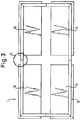
- Figure 1 shows a very simplified representation of the basic principle of the support system according to the invention, consisting of a base plate 1 and connected to this base plate 1 side walls 2, 3, so that a box structure with a receiving space 4 for the respective tub is created.
- This structure is adapted to the size of the tub to be accommodated.
- FIG. 2 shows a cross-sectional view through a support system according to the invention, this system being provided for mounting on a raw concrete ceiling, since the floor slab 1 has an insulation function.
- the side walls 2, 3 of the support system according to the invention are always constructed in sandwich construction and consist of a mechanically stable outer paneling 7 and one of them spaced inner layer 8, which can be made much less stable than the outer layer 7, as well as a completely or partially filling the space between the two layers 7, 8 soft spring material 5, z.
- the base plate 1 is designed at least for the case of mounting the support system on a raw concrete ceiling analogous to the side walls 2, 3, but has a mechanically stable inner layer 6 in order to be able to absorb the forces exerted by the trough properly.
- a normal, insulation-free plate can be used as base plate 1, since structure-borne noise insulation downwards is not required in this case.
- the use of a single-layer base plate offers the advantage of a lower overall height and of course also reduces the costs of the support system.
- the side walls 2, 3 are divided to facilitate storage and transport, so that partial side walls 2a, 2b are formed, which are connected to one another via hinges 9, which are arranged at different heights with respect to the individual side walls are. In this way, it is possible to fold down the side wall parts located at the top towards the bottom plate 1 and to obtain a small-volume stacking arrangement.
- An adaptation of the support system to the respective tub size can be made by appropriate selection of the sizes of the base plate 1 and the side walls 2 and 3, it being possible to provide basic designs of maximum size and to provide predetermined breaking incisions in the corresponding plates, so that on the construction site the corresponding The size can be adjusted if you do not know at the time of ordering the carrier system for which specific tub size this system is intended.
- Figure 3 shows an embodiment in which the different size requirements can be taken into account by a variable base plate 1.
- this base plate is divided into the longitudinal and transverse directions, so that four partial base plates 1a, 1b, 1c, 1d, preferably of the same size, are formed.
- These partial floor panels are connected to one another via a telescopic frame 10, i. H. over a frame that can be pulled apart in the longitudinal direction and / or in the transverse direction according to the respective requirements.
- individual telescopic members can also be arranged between the partial floor panels.
- a frame 10 provided in the outer circumferential area of the base plate 1 it can preferably be designed in the form shown in FIG. 4, since in this embodiment the telescopic frame simultaneously takes over the coupling function between the base plate 1 and the side walls 2, 3.
- Figure 4 shows the detail X from Figure 3 and shows that the telescopic frame 10 connected to the base plate 1 consists of a hollow profile 11 and a positively engaging rail 12 in this hollow profile, both the hollow profile 11 and the rail 12 with lateral vertical walls 13 are provided, are created by the U-profile receptacles for the side walls 2, 3.
- a further embodiment of the invention reduced to its minimally required components, can be used if the floating screed fully meets the requirements for structure-borne noise, since in in this case, the use of any base plate in connection with the support system can be dispensed with.
- the schematic representation according to FIG. 5 shows the arrangement of the support system receiving a tub edge 15 in front of a tiled wall.
- a profile part 14 with a lip 16 sealingly resting on the edge 15 of the tub is placed on the free upper side wall ends.
- the tub 15 lies with its edge 15 on the insulating material layer made of soft spring material 5 of the side wall, or on the corresponding inner planking or inner protective layer of this side wall, which is not specifically shown in FIG. 5, and it is readily apparent that due to this by the support system guaranteed connection technology between the tub edge 15 and the wall no structure-borne noise transmission can take place.
- the design of the profile part 14 is possible in various ways.
- this profile part can consist of elastic material, so that profile part 14 and sealing lip 16 can be made of the same material.
- the profile part shown in Figure 5 can also be carried out according to an expedient embodiment such that, starting from the upper transverse wall of the profile part, a web located between the sealing lip 16 and the side wall extends downward and the tub edge comes to rest against this web.
- This embodiment is particularly suitable for such side walls that have a stable and resilient inner paneling have, in this case, a structure-borne noise is prevented by the web located between the inner paneling and the edge of the tub made of insulating material in the required manner.
- a profile part made of stable and possibly coated in the required manner plastic material or metal or another non-elastic material is used, this profile part then having a receptacle for fixing an elastic sealing lip, which ensures the seal against the tub edge.
- This profile part can optionally also have a receptacle for fixing an insulating web which extends in the area between the tub edge and the inner paneling of the side wall.
- a stable profile part can also be provided with a longitudinally extending dome that engages in a corresponding groove in the side wall.
- FIG. 6 shows a conventional bathtub 20 which is supported on the base plate of a support system via support leg arrangements 21, the side walls 2 of which adjoin the respective tub edges and are flush with them.
- the base plate 1 consists of an inner layer 6 made of moisture-resistant material, which is arranged on a layer 5 made of soft resilient material or is connected to it.
- a stable outer paneling 7 can be provided on the underside, so that the z. B. from polystyrene, mineral wool, cork, coconut fibers or the like existing soft spring material between the inner layer 6 and the outer paneling 7 is included.
- the inner layer 6 of the base plate is divided into a central region 17 and an edge region 18, the central region 17 forming the actual tub support surface.
- the resulting between the central region 17 and the peripheral region 18 pronounced gap 19 is provided with air or with a gap filler 22, which consists, for example, of a closed-cell foam, the material used being Misselon (registered trademark of the applicant) with a tear-resistant surface.
- adjustable support members 23 are provided according to FIG. 7, which are accessible via recesses 24 in the inner layer and the soft-spring material 5. Since the outer paneling 7 is mechanically stable and preferably in the form of a hard plate, screw actuators can be fixed in this outer paneling 7 either directly or via inserted screw nuts, which enable stepless adjustment.
- hard foam blocks of different heights can also be inserted into corresponding recesses in the outer paneling instead of continuously adjustable adjusting members 23.
- FIG. 8 shows, in the form of a cutout, the connection of two partial side walls 2a, 2b via a clampable sliding guide 25.
- Two-part or multi-part side walls enable the carrier system to be easily adapted to different tub sizes, in which case correspondingly adjustable base plates are preferably also provided in connection with the adjustable side walls.
- the clampable sliding guide 25 consists of an open profile guide channel 26 and an elongated hole tab 27 which can be firmly connected to one another in different relative positions by means of a clamping screw 28.
- the profile guide channel 26 and the elongated hole tab 27 are fastened to the outer cladding of the respective side wall, ensure a stable connection of the partial side walls and enable the size of the respective side wall to be adjusted continuously.
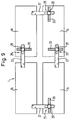
- FIG. 9 shows a base plate consisting of partial base plates 1a, 1b, 1c and 1d, which are connected to one another via clampable sliding guides 25 analogously to FIG. 8.
- the profile guide channels 26 and the respectively assigned elongated hole tabs 27 run perpendicular to one another, so that a continuous adjustment of the base plate in the direction of the length and the width is possible.
- the clamping screws 28 are easily accessible from the top of the base plate, so that the size adjustment can also be carried out without problems on the respective construction site.
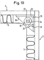
- FIG. 10 shows a preferred embodiment of coupling elements 29 for the current connection of side walls 2, 3.
- Each coupling element is formed by an angled part 30 fastened to a side wall, the free leg of which has a vertically running coupling slot 31, and by a fastened to the assigned second side wall Wedge hook part 32 which engages in the slot 31 and leads to a clamping lock between the two parts.
- a stable, non-positive and positive corner connection is created, which is very easy to implement and requires no tools or loose fastening parts.
- a transverse web 36 is integrated in the angle part 30.
- This crossbar 36 forms, together with a nut 37 welded to it, a support and guide element for a support rod 34 which extends in the vertical direction and is supported on the base plate.
- a support rod 34 which extends in the vertical direction and is supported on the base plate.
- FIG. 11 shows, in the form of a schematic partial sectional view, a specific embodiment of a side wall connection with an angled part 30 and a wedge hook part 32 extending over a substantial part of the side wall height, two superposed coupling points designed analogously to FIG. 10 being provided.
- the support rod 34 which is designed as a threaded spindle, extends through nuts 37 which are arranged coaxially and welded to transverse webs 36 and is supported in a positioning receptacle 35 on the edge region 18 of the base plate.
- the support rod 34 is easily accessible from above when the cover profile part 14 has not yet been attached and can, for. B. operated by a screwdriver, so that it is possible to make an exact height adjustment or adjustment of the side walls by means of the support rods 34 attached in the corner areas and to achieve that the outer paneling 7 of the side walls is exactly flush with the upper edge of the tub 20th lies and thus the cover profile part 14 can be attached correctly positioned, so that there is an exact and elegant connection between the tub edge and the profile part.
- FIG. 11 shows the installed state of the carrier system relative to a floor structure 40, the outer paneling 7 forming a carrier wall for a tiling 38 and the tiling just as the outer paneling 7 of the side wall is decoupled from the floor structure 40 in a sound-perfect manner.
- Figure 12 shows a side wall structure that allows support of the edge of the tub 20 and a z. B. has a wooden panel existing inner paneling 41, which extends between the central region 17 of the base plate and the underside of the tub edge and supports this tub edge directly, so that in the case of loads from tub users no undesirable deflection of the tub edge can occur.
- the insulating material provided between the inner paneling 41 and the outer paneling 7 preferably has a recess 51 in the tub edge area, in which the outer, downwardly bent part of the tub edge is preferably received in a form-fitting manner.
- FIG. 13 shows a further embodiment variant of a tub edge support, in which the inner paneling 41 has a telescopically height-adjustable support wall 45, which can be adjusted, for example, via an angular screw mechanism 46.
- a telescopically height-adjustable support wall 45 which can be adjusted, for example, via an angular screw mechanism 46.
- the side wall extends into the cavity formed by the tub rim, so that the tub rim is a visible element and the tiling can begin a short distance below the tub rim and can be arranged flush with the outside tub rim or indented.
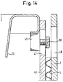
- FIG. 14 shows a further variant of a tub edge support, in this case, on the inside of the inner cladding 41, height-adjustable and externally clampable support blocks 49 are provided via elongated holes 47, which can be fixed at the required height by means of clamping screws 50. These clamping screws 50 are accessible via corresponding elongated holes 48 in the outer paneling 7, but are no longer visible after the outer paneling has been tiled.
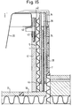
- FIG. 15 shows, in the form of a schematic illustration, a partially sectioned sectional illustration of a variant of the invention that has an optimal adjustment and setting option.
- the support rods 34 provided for height adjustment of the side walls no longer have to be arranged in the corner areas, but rather are integrated directly into the outer paneling 7 of the side walls, which are provided with through holes 39 for this purpose.
- a nut 44 is preferably integrated on the bottom, with which the respective threaded rod 34 is screwed.
- the support rods 34 are supported on the edge region 18 decoupled from the central region 17 of the base plate.
- the support rods 34 are accessible from above, so that the height adjustment can be done very simply by means of a screwdriver.
- the tub edge support is realized in this embodiment via support blocks 49 which are arranged in vertical bores 42 of the inner paneling 41 of the side walls. By turning this screw spindle 43, which in turn is easily accessible from above, the required height adjustment of the support block 49 can take place.
- This profile cover is preferably formed in the form of a composite system, i. H. it consists of a soft inner layer, which ensures acoustic decoupling, and a comparatively hard and also sturdy outer layer, which can be adapted or contrasted with regard to the color of the tub.
- the carrier system according to the invention despite the simple structure with regard to the required structure-borne sound insulation, yields optimal results, is extremely simple in construction and can be assembled and also ensures problem-free size adaptation to the respective tub.
Landscapes
- Health & Medical Sciences (AREA)
- Public Health (AREA)
- Epidemiology (AREA)
- General Health & Medical Sciences (AREA)
- Devices For Medical Bathing And Washing (AREA)
- Floor Finish (AREA)
- Finishing Walls (AREA)
- Catalysts (AREA)
Abstract
Description
Die Erfindung betrifft ein Trägersystem für eine Bade- oder Brausewanne nach dem Oberbegriff des Anspruchs 1.The invention relates to a support system for a bath or shower tray according to the preamble of
Ein derartiges Trägersystem ist aus der FR-A-2 451 736 bekannt. Dieses besteht in einer Grundausführung aus einem Halterahmen mit im wesentlichen rechtwinkligem Querschnitt, der vertikale Seitenwände sowie eine am oberen Bereich der Seitenwände angeordnete und sich etwa senkrecht zu diesen nach innen erstreckende Umrandung umfaßt. Die Seitenwände sind mit horizontalen Verstärkungsrippen versehen. Dieser bekannte Halterahmen besitzt in einigen Ausführungsformen entweder keinen eigenen Boden, wobei in diesem Fall senkrecht zu den Seitenwänden verlaufende Balken vorgesehen sein können, die eine Auflage für die jeweilige Wanne bilden, oder ist mit einem einstückig mit den Seitenwänden ausgebildeten Boden versehen. Zumindest die Seitenwände dieses bekannten Halterahmens können aus zellenartigem Polystyrol bestehen und wenigstens auf der Außenseite mit glasfaserverstärktem Kunststoff verkleidet werden.Such a carrier system is known from FR-A-2 451 736. In a basic version, this consists of a holding frame with an essentially rectangular cross-section, which comprises vertical side walls and a border which is arranged at the upper region of the side walls and extends inward approximately perpendicularly to these. The side walls are provided with horizontal reinforcement ribs. In some embodiments, this known holding frame either does not have its own floor, in which case beams running perpendicular to the side walls can be provided, which form a support for the respective trough, or is provided with a floor formed in one piece with the side walls. At least the side walls of this known holding frame can consist of cell-like polystyrene and can be clad at least on the outside with glass fiber reinforced plastic.
Bei der Montage von Bade- und auch Brausewannen besteht jedoch generell das Problem, daß durch die sich beim Einbau ergebenden Verbindungen mit dem Baukörper Brücken zur Körperschallübertragung entstehen, die nicht nur unerwünscht sind, sondern es häufig auch verhindern, daß den bestehenden Vorschriften und anerkannten Regeln der Technik bezüglich der Körperschalldämmung Rechnung getragen wird.
Auch wenn es möglich sein sollte, die geforderte Körperschalldämmung nach unten aufgrund der sich unterhalb des schwimmenden Estrichs befindenden Wärme- und Trittschalldämmung in der erforderlichen Weise zu gewährleisten, so bleibt das Problem, daß über die Wannenränder und insbesondere auch über die vor der Wanne anzubringende Schürze ausgesprochen störende Schallbrücken entstehen.When assembling baths and shower trays, however, there is generally the problem that bridges for structure-borne noise transmission are created by the resulting connections to the structure, which are not only undesirable, but also often prevent the existing regulations and recognized rules the technology regarding structure-borne sound insulation is taken into account.
Even if it should be possible to ensure the required structure-borne sound insulation downwards due to the heat and impact sound insulation located below the floating screed, the problem remains that over the tub edges and in particular also over the apron to be attached in front of the tub extremely disruptive sound bridges arise.
Grundsätzlich möglich wäre es zwar, durch gezielte und auch aufwendige Maßnahmen bei der Montage derartiger Wannen die geforderte Schalldämmung bzw. Körperschalldämmung zu erreichen, aber derartige Spezialmontagen sind auf normalen Baustellen, wo im Regelfall unter Zeit- und Kostendruck und auch mit weniger qualifizierten Personen gearbeitet werden muß, nicht zu realisieren.In principle, it would be possible to achieve the required sound insulation or structure-borne sound insulation through targeted and also complex measures when installing such tubs, but such special assemblies are on normal construction sites, where work is usually done under time and cost pressure and also with less qualified people must not realize.
Aufgabe der Erfindung ist es daher, ein Trägersystem für Bade- oder Brausewannen zu schaffen, das äußerst einfach handhabbar und ohne besondere Fachkenntnisse sachgerecht montierbar ist und dabei sicherstellt, daß störende Körperschallübertragungen zwangsläufig ausgeschlossen werden und damit eine sachgerechte und den bestehenden Bestimmungen und anerkannten Regeln der Technik entsprechende Wannenmontage gewährleistet wird.The object of the invention is therefore to provide a carrier system for bathtubs or shower trays which is extremely easy to handle and can be assembled properly without special technical knowledge and thereby ensures that disruptive structure-borne noise transmissions are inevitably ruled out and thus a proper and the existing provisions and recognized rules of Appropriate tub installation is guaranteed.
Gelöst wird diese Aufgabe nach der Erfindung durch die Merkmale im kennzeichnenden Teil des Anspruchs 1.This object is achieved according to the invention by the features in the characterizing part of
Durch dieses Grundkonzept wird eine am jeweiligen Aufstellort der Wanne anzubringende bzw. zusammenzusetzende Wannenaufnahme geschaffen, die unter Gewährleistung eines einfachen Wanneneinbaus zumindest hinsichtlich der kritischen Wannenränder eine schalltechnische Entkoppelung vom Baukörper erbringt und jegliche Körperschallbrückenbildung ausschließt.
Wird dieses Trägersystem auf einem funktionsfähigen, in akustischer Hinsicht zumindest der schalldämmenden Sandwich-Bodenplatte adäquaten schwimmenden Estrich angebracht, dann kann die sich unterhalb der Estrichschicht befindende Wärme- und Trittschalldämmung auch die Körperschalldämmung der Wanne nach unten übernehmen, und die Bodenplatte des Trägersystems kann als normale, ungedämmte Platte ausgeführt werden.
Wird das Trägersystem jedoch auf der Rohbetondecke angebracht, dann wird als Bodenplatte eine analog den Seitenwänden ausgebildete schalldämmende Sandwichplatte verwendet, so daß in diesem Falle die schalltechnische Entkoppelung der jeweiligen Wanne vom Baukörper vollständig durch das Trägersystem übernommen wird.This basic concept creates a bathtub receptacle to be attached or assembled at the respective installation site of the bathtub, which provides sound decoupling from the structure at least with regard to the critical bathtub edges while ensuring simple tub installation and precludes any structure-borne noise bridge.
If this support system is installed on a functional screed that is at least acoustically adequate for the sound-absorbing sandwich floor slab, then the thermal and impact sound insulation located below the screed layer can also take over the structure-borne sound insulation of the tub, and the floor slab of the support system can function as normal , uninsulated panel.
However, if the support system is attached to the raw concrete ceiling, a sound-absorbing sandwich panel designed analogously to the side walls is used as the base plate, so that in this case the acoustic decoupling of the respective tub from the structure is completely taken over by the support system.
Bei den sandwichartig ausgebildeten Seitenwänden ist die die Außenbeplankung darstellende Schicht mechanisch fest und vorzugsweise feuchtigkeitsresistent ausgebildet. Die innenliegende Schicht, an der der Wannenrand nach erfolgter Wannenmontage anliegt, kann ebenfalls mechanisch fest ausgebildet sein oder gegebenenfalls nur aus einer mechanisch schwachen Deckschicht bestehen, deren Hauptaufgabe es ist, die eigentliche Dämmschicht vor Beschädigung zu schützen.In the case of the sandwich-like side walls, the layer representing the outer planking is mechanically firm and preferably moisture-resistant. The inner layer, against which the tub rim rests after the tub has been installed, can also be mechanically strong or, if necessary, only consist of a mechanically weak top layer, the main task of which is to protect the actual insulation layer from damage.
Bevorzugt ist das Trägersystem so gestaltet, daß die Bodenplatte mit den Seitenwänden über Steckverbindungen, z. B. unter Verwendung von U-Profilaufnahmen, kuppelbar ist, wobei die Eckbereiche über Steckkappen, Spannverschlüsse und dergleichen gegenseitig fixierbar sind.The carrier system is preferably designed so that the base plate with the side walls via plug connections, for. B. using U-profile receptacles, can be coupled, the corner areas can be mutually fixed via plug caps, latches and the like.
Das Trägersystem nach der Erfindung wird in der einfachsten Ausführungsform in einigen wenigen Abmessungen bereitgestellt, die an feste Normabmessungen der Wannen angepaßt sind. Es ist aber auch zur Anpassung des Trägersystems an unterschiedliche Wannengrößen möglich, gemäß einer Ausführungsvariante der Erfindung die Bodenplatte und die Seitenwände mit an die Wannen-Normgrößen angepaßten Sollbrucheinschnitten versehen, so daß auch auf der Baustelle problemfrei aus Standard-Grundelementen das jeweils passende System zusammengestellt werden kann.In the simplest embodiment, the carrier system according to the invention is provided in a few dimensions which are adapted to fixed standard dimensions of the tubs. However, it is also possible to adapt the support system to different tub sizes, in accordance with one embodiment variant of the invention providing the base plate and the side walls with predetermined breaking incisions adapted to the standard tub sizes, so that the appropriate system can be put together on site from standard basic elements without any problems can.
Nach einer besonderen Ausgestaltung der Erfindung kann diese Größenanpassung auch dadurch erfolgen, daß eine größenverstellbare Bodenplatte vorgesehen wird, wobei die Größenverstellung dadurch erreicht wird, daß die Bodenplatte zumindest zweiteilig ausgebildet und die beiden Teile über teleskopierbare Organe miteinander gekuppelt werden. Diese in ihrer Größe variable Bodenplatte kann dann mit den jeweils passenden Seitenwänden kombiniert werden, wobei es sich dabei wiederum um Seitenwände handeln kann, die dem jeweiligen Einsatzfall durch Größenreduzierung über Sollbruchstellen anpaßbar sind.According to a special embodiment of the invention, this size adjustment can also take place in that a size-adjustable base plate is provided, the size adjustment being achieved in that the base plate is formed at least in two parts and the two parts are coupled to one another via telescopic organs. This base plate, which is variable in size, can then be combined with the appropriate side walls, which in turn can be side walls which can be adapted to the respective application by reducing the size via predetermined breaking points.
Die Anpassung und Abdichtung des Trägersystems bezüglich der jeweiligen Wanne erfolgt vorzugsweise über auf die oberen freien Seitenwandenden aufsteckbare Kuppel- oder Abschlußprofilteile, welche aus einem elastischen Material bestehen können, vorzugsweise aber von einem Formteil gebildet werden, das eine Aufnahme zum Einsetzen einer Dichtlippe aufweist, die im montierten Zustand unter Vorspannung auf dem Wannenrand aufliegt. Das Profilteil kann dabei aus Metall oder Kunststoff, bzw. beschichtetem Kunststoffmaterial bestehen, so daß ein ästhetisch einwandfreies und ansprechendes Erscheinungsbild erhalten wird.The adaptation and sealing of the carrier system with respect to the respective trough is preferably carried out via dome or end profile parts which can be plugged onto the upper free side wall ends and which can consist of an elastic material, but are preferably formed by a molded part which has a receptacle for inserting a sealing lip which in the assembled state under prestress on the tub rim. The profile part can be made of metal or plastic, or coated plastic material exist so that an aesthetically perfect and appealing appearance is obtained.
Wesentlich für eine weitere bevorzugte Ausführungsform ist, daß die Bodenplatte zumindest eine Innenschicht und eine darunter angeordnete Schicht aus weichfederndem Material umfaßt und zumindest der zur Wannenabstützung bestimmte Mittelbereich der Innenschicht der Bodenplatte von dem Randbereich der Innenschicht getrennt und akustisch entkoppelt ist.It is essential for a further preferred embodiment that the base plate comprises at least one inner layer and a layer of soft resilient material arranged underneath and that at least the central region of the inner layer of the base plate intended for tub support is separated from the edge region of the inner layer and acoustically decoupled.
Bevorzugt sind dabei die insbesondere aus einem feuchtigkeitsresistenten Material bestehende Innenschicht des Mittelbereichs und der Randbereich der Innenschicht auf einer gemeinsamen Schicht aus weichfederndem Material angeordnet und mit dieser Schicht verbunden.In this case, the inner layer of the central region, which consists in particular of a moisture-resistant material, and the edge region of the inner layer are preferably arranged on a common layer of soft-resilient material and connected to this layer.
Durch diese Ausgestaltung der Bodenplatte wird ein akustisch entkoppelter, die Hauptabstützfunktion für die Wanne übernehmender Mittelbereich geschaffen, während der Randbereich zur Abstützung der Seitenwände dient, die gemäß spezieller Ausgestaltungen auch noch die Funktion einer Wannenrandabstützung übernehmen können.This design of the base plate creates an acoustically decoupled central area, which takes over the main support function for the tub, while the edge area serves to support the side walls, which, according to special configurations, can also take on the function of tub edge support.
Die Bodenplatte wird bevorzugt in Sandwichbauweise ausgeführt, wobei an der mechanisch stabilen Außenbeplankung zur Justierung der Bodenplatte verstell- oder auswechselbare Stützorgane vorgesehen sein können. Im Falle der Verwendung auswechselbarer Stützorgane kann es sich um in entsprechende Ausnehmungen einsetzbare Stützblöcke unterschiedlicher Abmessungen handeln, während im Falle verstellbar ausgeführter Stützorgane in der stabil ausgeführten Außenbeplankung über eine Schraubverstellung einjustierbare Organe gehaltert sein können.The base plate is preferably designed in a sandwich construction, wherein adjustable or exchangeable support members can be provided on the mechanically stable outer paneling for adjusting the base plate. In the case of the use of interchangeable support members, support blocks of different dimensions can be inserted into corresponding recesses, while in the case of adjustable support members, organs that can be adjusted can be held in the sturdy outer planking by means of a screw adjustment.
Die Bodenplatte und/oder die Seitenwände können zur Anpassung an unterschiedliche Wannengrößen jeweils mehrteilig ausgebildet sein, wobei die verschiedenen Teile über verklemmbare Schiebeführungen miteinander verbunden sind, die innenliegend an der Außenbeplankung befestigt werden.The base plate and / or the side walls can each be designed in several parts in order to adapt to different tub sizes, the various parts being connected to one another via clampable sliding guides which lie on the inside to be attached to the outer paneling.
Die gegenseitige Verbindung der Seitenwände zur Schaffung eines stabilen, auf der Bodenplatte abstützbaren Kastenrahmens erfolgt bevorzugt mittels an den Inneneckbereichen an der Außenbeplankung befestigter, selbstverkeilender Kuppelorgane, wobei diese Kuppelorgane bevorzugt aus einem an einer Seitenwand angebrachten Winkelteil mit einem Kuppelschlitz und einem in den Kuppelschlitz klemmend eingreifenden, an der anderen Seitenwand befestigten Keilhakenteil bestehen. Mittels derartiger Kuppelorgane wird eine einfach und schnell herstellbare, zu hoher mechanischer Festigkeit führende Verbindung geschaffen.The mutual connection of the side walls to create a stable box frame that can be supported on the base plate is preferably carried out by means of self-wedging coupling elements fastened to the inner panel areas on the outer paneling, these coupling elements preferably comprising an angled part attached to a side wall with a coupling slot and a clamping engagement in the coupling slot , there are wedge hook parts attached to the other side wall. By means of such coupling elements, a connection which leads to high mechanical strength and can be produced quickly and easily is created.
Um die Seitenwände in ihrer Höhe justieren und mit der jeweiligen Wanne bündig ausrichten zu können, sind diese Seitenwände bezüglich der Bodenplatte höhenverstellbar ausgeführt, wobei diese Höhenverstellung über Schraubspindeln erfolgen kann, die in Positionieraufnahmen der Bodenplatte abgestützt sind.In order to adjust the height of the side walls and to align them flush with the respective trough, these side walls are designed to be height-adjustable with respect to the base plate, this height adjustment being able to be carried out using screw spindles which are supported in positioning receptacles of the base plate.
Nach einer bevorzugten Ausgestaltung der Erfindung sind diese verstellbaren Stützstäbe in die Kuppelorgane zur Verbindung der Seitenwände integriert.According to a preferred embodiment of the invention, these adjustable support rods are integrated in the coupling elements for connecting the side walls.
Gemäß einer weiteren Besonderheit der Erfindung ist der Rand der jeweiligen Wanne zumindest bereichsweise auf der Innenbeplankung der Seitenwände abgestützt, wobei diese Innenbeplankung ihrerseits bevorzugt auf dem Mittelbereich der Bodenplatte abgestützt ist, so daß sich eine optimale akustische Entkoppelung ergibt und dennoch die Wannenränder ohne die Gefahr des Durchbiegens vom Wannenbenutzer auch stark belastet werden können.According to a further special feature of the invention, the edge of the respective tub is supported at least in regions on the inner paneling of the side walls, this inner paneling in turn being preferably supported on the central region of the base plate, so that there is optimal acoustic decoupling and yet the tub edges are without the risk of Deflection can also be heavily loaded by the tub user.
Um eine sichere Abstützung der Wannenränder zu gewährleisten, ist die Innenbeplankung der Seitenwände entweder mit einer teleskopisch höhenverstellbaren Stützwand versehen oder es sind an dieser Innenbeplankung höhenverstellbare, Wannenrandabstützungen bildende Stützblöcke vorgesehen.In order to ensure secure support of the tub edges, the inner paneling of the side walls is either provided with a telescopically height-adjustable support wall or there are height-adjustable, Support blocks forming tub edge supports are provided.
Weitere vorteilhafte Ausgestaltungen und Merkmale der Erfindung sind in den Unteransprüchen angegeben.Further advantageous refinements and features of the invention are specified in the subclaims.
Die Erfindung wird nachfolgend unter Bezugnahme auf die Zeichnung näher erläutert; in der Zeichnung zeigt:
Figur 1- eine schematische perspektivische Ansicht einer Grundausführungsform des Trägersystems nach der Erfindung,
Figur 2- eine Querschnittsansicht einer weiteren Ausführungsform eines Trägersystems nach der Erfindung,
- Figur 3
- eine schematische Darstellung einer größenverstellbar ausgeführten Bodenplatte,
Figur 4- eine vergrößerte Darstellung der Einzelheit X nach Figur 3,
Figur 5- eine schematische Teilschnittdarstellung eines Trägersystems nach der Erfindung mit eingebauter Wanne vor einer verfliesten Wand,
Figur 6- eine schematische Darstellung eines weiteren Trägersystems nach der Erfindung mit in diesem System angeordneter Badewanne,
Figur 7- eine Detaildarstellung einer Justiervorrichtung für die Bodenplatte des Trägersystems nach
Figur 6, - Figur 8
- eine Ausschnittsdarstellung einer verklemmbaren Schiebeführung zwischen Teilbodenplatten oder Teilseitenwänden,
- Figur 9
- eine schematische Draufsicht einer mehrteiligen, teleskopierbar ausgeführten Bodenplatte,
Figur 10- einen von zwei Seitenwänden gebildeten Eckbereich mit Kuppelorganen,
Figur 11- eine schematische Schnittdarstellung eines vorderseitigen Teilbereichs eines montierten Trägersystems nach der Erfindung,
Figur 12- eine schematische Teildarstellung einer Ausführungsform einer Wannenrandabstützung,
Figur 13- eine schematische Darstellung einer Variante einer Wannenrandabstützung,
Figur 14- eine schematische Darstellung einer weiteren Variante einer Wannenrandabstützung, und
Figur 15- eine im wesentlichen der Figur 11 entsprechende Darstellung einer weiteren Ausführungsform der Erfindung.
- Figure 1
- 2 shows a schematic perspective view of a basic embodiment of the carrier system according to the invention,
- Figure 2
- 2 shows a cross-sectional view of a further embodiment of a carrier system according to the invention,
- Figure 3
- 1 shows a schematic representation of a size-adjustable bottom plate,
- Figure 4
- 3 shows an enlarged illustration of the detail X according to FIG. 3,
- Figure 5
- 2 shows a schematic partial sectional view of a carrier system according to the invention with a built-in tub in front of a tiled wall,
- Figure 6
- 1 shows a schematic representation of a further carrier system according to the invention with a bathtub arranged in this system,
- Figure 7
- 6 shows a detailed illustration of an adjusting device for the base plate of the carrier system according to FIG. 6,
- Figure 8
- a sectional view of a clampable sliding guide between partial floor panels or partial side walls,
- Figure 9
- 1 shows a schematic top view of a multi-part, telescopic base plate,
- Figure 10
- a corner area formed by two side walls with dome elements,
- Figure 11
- 2 shows a schematic sectional illustration of a front-side partial area of an assembled carrier system according to the invention,
- Figure 12
- 2 shows a schematic partial representation of an embodiment of a tub edge support,
- Figure 13
- a schematic representation of a variant of a tub edge support,
- Figure 14
- a schematic representation of a further variant of a tub edge support, and
- Figure 15
- a representation of another embodiment of the invention substantially corresponding to FIG. 11.
Figur 1 zeigt in stark vereinfachter Darstellung das Grundprinzip des Trägersystems nach der Erfindung, bestehend aus einer Bodenplatte 1 sowie mit dieser Bodenplatte 1 verbundenen Seitenwänden 2, 3, so daß eine Kastenstruktur mit einem Aufnahmeraum 4 für die jeweilige Wanne entsteht. Diese Struktur ist an die Größe der aufzunehmenden Wanne angepaßt.Figure 1 shows a very simplified representation of the basic principle of the support system according to the invention, consisting of a
Figur 2 zeigt eine Querschnittsdarstellung durch ein Trägersystem nach der Erfindung, wobei dieses System zur Montage auf einer Rohbetondecke vorgesehen ist, da die Bodenplatte 1 Dämmfunktion besitzt.FIG. 2 shows a cross-sectional view through a support system according to the invention, this system being provided for mounting on a raw concrete ceiling, since the
Die Seitenwände 2, 3 des Trägersystems nach der Erfindung sind stets in Sandwichbauweise ausgeführt und bestehen aus einer mechanisch stabilen Außenbeplankung 7 und einer davon beabstandeten Innenschicht 8, die wesentlich weniger stabil als die Außenschicht 7 ausgeführt sein kann, sowie einem den Raum zwischen den beiden Schichten 7, 8 ganz oder teilweise ausfüllenden weichfedernden Material 5, z. B. Mineralfasermaterial oder geschäumtem Kunststoff.The
Die Bodenplatte 1 ist zumindest für den Fall der Montage des Trägersystems auf einer Rohbetondecke analog den Seitenwänden 2, 3 ausgebildet, besitzt aber eine mechanisch stabile Innenschicht 6, um die von der Wanne ausgeübten Kräfte einwandfrei aufnehmen zu können.The
Für den Fall der Montage des Trägersystems auf einem schwimmenden Estrich, wenn eine Körperschalldämmung nach unten nicht erforderlich ist, kann als Bodenplatte 1 eine normale, dämmstofffreie Platte verwendet werden, da in diesem Falle eine Körperschalldämmung nach unten nicht erforderlich ist. Die Verwendung einer einschichtigen Bodenplatte erbringt dabei den Vorteil einer geringeren Gesamtbauhöhe und reduziert natürlich auch die Kosten des Trägersystems.In the case of mounting the support system on a floating screed, when structure-borne noise insulation downwards is not required, a normal, insulation-free plate can be used as
Bei der in Figur 2 dargestellten Ausführungsform sind zur Erleichterung der Lagerung und des Transports die Seitenwände 2, 3 unterteilt, so daß Teil-Seitenwände 2a, 2b entstehen, welche über Scharniere 9 miteinander verbunden sind, die bezogen auf die einzelnen Seitenwände in unterschiedlicher Höhe angeordnet sind. Auf diese Weise ist es möglich, die jeweils obenliegenden Seitenwandteile nach innen zur Bodenplatte 1 hin umzuklappen und eine kleinvolumige Stapelanordnung zu erhalten.In the embodiment shown in Figure 2, the
Eine Anpassung des Trägersystems an die jeweilige Wannengröße kann durch entsprechende Wahl der Größen der Bodenplatte 1 und der Seitenwände 2 und 3 erfolgen, wobei es möglich ist, jeweils Grundausführungen maximaler Größe vorzusehen und in den entsprechenden Platten Sollbruch-Einschnitte vorzusehen, so daß auf der Baustelle die entsprechende Größenanpassung vorgenommen werden kann, wenn man zum Zeitpunkt der Bestellung des Trägersystems noch nicht weiß, für welche konkrete Wannengröße dieses System bestimmt ist.An adaptation of the support system to the respective tub size can be made by appropriate selection of the sizes of the
Figur 3 zeigt eine Ausführungsform, bei der den unterschiedlichen Größenanforderungen durch eine variable Bodenplatte 1 Rechnung getragen werden kann. Dazu ist diese Bodenplatte in Längs- und Querrichtung unterteilt, so daß vier vorzugsweise gleichgroße Teilbodenplatten 1a, 1b, 1c, 1d entstehen. Diese Teilbodenplatten sind miteinander über einen teleskopierbaren Rahmen 10 verbunden, d. h. über einen Rahmen, der in Längsrichtung und/oder in Querrichtung entsprechend den jeweiligen Anforderungen auseinandergezogen werden kann.Figure 3 shows an embodiment in which the different size requirements can be taken into account by a
Anstelle eines geschlossenen Rahmens können auch einzelne teleskopierfähige Organe zwischen den Teilbodenplatten angeordnet sein.Instead of a closed frame, individual telescopic members can also be arranged between the partial floor panels.
Bei Verwendung eines im Außenumfangsbereich der Bodenplatte 1 vorgesehenen Rahmens 10, kann dieser vorzugsweise in der in Figur 4 gezeigten Form ausgestaltet sein, da bei dieser Ausführungsform der teleskopierbare Rahmen gleichzeitig Kupplungsfunktion zwischen Bodenplatte 1 und Seitenwänden 2, 3 übernimmt.When using a
Figur 4 zeigt die Einzelheit X aus Figur 3 und läßt erkennen, daß der teleskopierbare, mit der Bodenplatte 1 verbundene Rahmen 10 aus einem Hohlprofil 11 und einer formschlüssig in dieses Hohlprofil eingreifenden Schiene 12 besteht, wobei sowohl das Hohlprofil 11 als auch die Schiene 12 mit seitlichen Vertikalwänden 13 versehen sind, durch die U-Profilaufnahmen für die Seitenwände 2, 3 geschaffen werden.Figure 4 shows the detail X from Figure 3 and shows that the
Eine weitere, auf ihre minimal erforderlichen Bestandteile reduzierte Ausführungsform der Erfindung kann dann verwendet werden, wenn der schwimmende Estrich den körperschalldämmenden Anforderungen in vollem Umfange genügt, da in diesem Falle auf die Verwendung jeglicher Bodenplatte im Zusammenhang mit dem Trägersystem verzichtet werden kann. Mittels der körperschalldämmend ausgeführten Seitenwände ist es in diesem Falle alleine möglich, die akustischen Probleme zwischen Wanne und Wannenschürze einerseits und dem Baukörper andererseits zu beseitigen, wobei diese Seitenwände relativ zueinander durch Form- und/oder kraftschlüssig wirkende Eckverbindungen zu einer Rechteckrahmenanordnung stabilisiert werden.A further embodiment of the invention, reduced to its minimally required components, can be used if the floating screed fully meets the requirements for structure-borne noise, since in in this case, the use of any base plate in connection with the support system can be dispensed with. In this case, it is only possible to eliminate the acoustic problems between the tub and the tub apron on the one hand and the structure on the other hand by means of the structure-borne soundproofing side walls, these side walls being stabilized relative to each other by form and / or non-positive corner connections to form a rectangular frame arrangement.
Die schematische Darstellung nach Figur 5 zeigt die Anordnung des einen Wannenrand 15 aufnehmenden Trägersystems vor einer gefliesten Wand. Auf die freien oberen Seitenwandenden ist dabei ein Profilteil 14 mit einer auf dem Rand 15 der Wanne abdichtend aufliegenden Lippe 16 gesteckt. Die Wanne liegt mit ihrem Rand 15 an der Dämmstoffschicht aus weichfederndem Material 5 der Seitenwand, bzw. an der entsprechenden, in Figur 5 nicht speziell gezeichneten Innen-Beplankung oder Innen-Schutzschicht dieser Seitenwand an, und es ist ohne weiteres ersichtlich, daß aufgrund dieser durch das Trägersystem gewährleisteten Anschlußtechnik zwischen Wannenrand 15 und Wand keinerlei Körperschallübertragung erfolgen kann.The schematic representation according to FIG. 5 shows the arrangement of the support system receiving a
Die Ausgestaltung des Profilteils 14 ist in verschiedener Weise möglich.The design of the
Grundsätzlich kann dieses Profilteil aus elastischem Material bestehen, so daß Profilteil 14 und Dichtlippe 16 materialeinheitlich ausgeführt werden können.Basically, this profile part can consist of elastic material, so that
Das in Figur 5 gezeigte Profilteil kann nach einer zweckmäßigen Ausgestaltung auch so ausgeführt werden, daß sich ausgehend von der oberen Querwand des Profilteils ein zwischen Dichtlippe 16 und der Seitenwand gelegener Steg nach unten erstreckt und der Wannenrand an diesem Steg zur Anlage kommt. Diese Ausführungsform eignet sich insbesondere für solche Seitenwände, die eine stabile und belastbare Innenbeplankung aufweisen, wobei in diesem Falle eine Körperschallübertragung durch den sich zwischen Innenbeplankung und Wannenrand befindenden Steg aus in der erforderlichen Weise dämmendem Material verhindert wird.The profile part shown in Figure 5 can also be carried out according to an expedient embodiment such that, starting from the upper transverse wall of the profile part, a web located between the sealing lip 16 and the side wall extends downward and the tub edge comes to rest against this web. This embodiment is particularly suitable for such side walls that have a stable and resilient inner paneling have, in this case, a structure-borne noise is prevented by the web located between the inner paneling and the edge of the tub made of insulating material in the required manner.
Vorzugsweise wird ein Profilteil aus stabilem und gegebenenfalls in der erforderlichen Weise beschichtetem Kunststoffmaterial oder auch aus Metall oder einem anderen nicht elastischen Werkstoff verwendet, wobei dieses Profilteil dann eine Aufnahme zur Fixierung einer elastischen Dichtlippe besitzt, die die Abdichtung gegenüber dem Wannenrand gewährleistet. Dieses Profilteil kann gegebenenfalls auch eine Aufnahme zur Fixierung eines Dämmsteges besitzen, der sich in dem Bereich zwischen Wannenrand und Innenbeplankung der Seitenwand erstreckt. Ein stabil ausgebildetes Profilteil kann auch mit einem in Längsrichtung verlaufenden Kuppelsteg versehen sein, der in eine entsprechende Nut der Seitenwand eingreift.Preferably, a profile part made of stable and possibly coated in the required manner plastic material or metal or another non-elastic material is used, this profile part then having a receptacle for fixing an elastic sealing lip, which ensures the seal against the tub edge. This profile part can optionally also have a receptacle for fixing an insulating web which extends in the area between the tub edge and the inner paneling of the side wall. A stable profile part can also be provided with a longitudinally extending dome that engages in a corresponding groove in the side wall.
Figur 6 zeigt eine konventionelle Badewanne 20, die über Stützfußanordnungen 21 auf der Bodenplatte eines Trägersystems abgestützt ist, dessen Seitenwände 2 an die jeweiligen Wannenränder angrenzen und mit diesen bündig abschließen.FIG. 6 shows a
Die Bodenplatte 1 besteht aus einer Innenschicht 6 aus feuchtigkeitsresistentem Material, die auf einer Schicht 5 aus weichfederndem Material angeordnet bzw. mit dieser verbunden ist. Zur Ausbildung einer Sandwichstruktur kann unterseitig eine stabile Außenbeplankung 7 vorgesehen sein, so daß das z. B. aus Polystyrol, Mineralwolle, Kork, Kokosfasern oder dergleichen bestehende weichfedernde Material zwischen der Innenschicht 6 und der Außenbeplankung 7 eingeschlossen ist.The
Die Innenschicht 6 der Bodenplatte ist in einen Mittelbereich 17 und in einen Randbereich 18 unterteilt, wobei der Mittelbereich 17 die eigentliche Wannenstützfläche bildet. Der sich zwischen Mittelbereich 17 und Randbereich 18 ergebende, ausgeprägt ausgebildete Spalt 19 ist mit Luft oder mit einem Spaltfüller 22 versehen, der beispielsweise aus einem geschlossenzelligen Schaum besteht, wobei als Material Misselon (eingetragenes Warenzeichen der Anmelderin) mit reißfester Oberfläche verwendbar ist.The
Durch die Trennung von Mittelbereich 17 und Randbereich 18 wird eine besonders wirksame akustische Entkoppelung der Wanne 20 vom jeweiligen Baukörper erzielt und außerdem erreicht, daß die Seitenwände des Trägersystems auf dem vom Mittelbereich 17 akustisch entkoppelten Randbereich 18 abgestützt werden können.By separating the
Um eine einfache und exakte Justierung des die Wanne tragenden Mittelbereichs 17 zu ermöglichen, sind entsprechend Figur 7 justierbare Stützorgane 23 vorgesehen, die über Ausnehmungen 24 in der Innenschicht sowie dem weichfedernden Material 5 zugänglich sind. Da die Außenbeplankung 7 mechanisch stabil und vorzugsweise in Form einer harten Platte ausgeführt ist, lassen sich in dieser Außenbeplankung 7 entweder direkt oder über eingesetzte Schraubmuttern Schraub-Stellorgane fixieren, die eine stufenlose Justierung ermöglichen.In order to enable simple and exact adjustment of the
Gemäß einer einfacheren Ausgestaltung können anstelle von stufenlos verstellbaren Justierorganen 23 auch in entsprechende Ausnehmungen in der Außenbeplankung 7 Hartschaumblöcke unterschiedlicher Höhe eingesetzt werden.According to a simpler embodiment, hard foam blocks of different heights can also be inserted into corresponding recesses in the outer paneling instead of continuously
Figur 8 zeigt in Form einer ausschnittsweisen Darstellung die Verbindung zweier Teilseitenwände 2a, 2b über eine verklemmbare Schiebeführung 25.FIG. 8 shows, in the form of a cutout, the connection of two
Zwei- oder mehrteilige Seitenwände ermöglichen eine einfache Anpassung des Trägersystems an unterschiedliche Wannengrößen, wobei in Verbindung mit den verstellbaren Seitenwänden vorzugsweise auch entsprechend verstellbare Bodenplatten vorgesehen sind.Two-part or multi-part side walls enable the carrier system to be easily adapted to different tub sizes, in which case correspondingly adjustable base plates are preferably also provided in connection with the adjustable side walls.
Die verklemmbare Schiebeführung 25 besteht gemäß dieser Ausführungsform aus einem offenen Profilführungskanal 26 und einer Langlochlasche 27, die über eine Klemmschraube 28 in unterschiedlichen Relativpositionen fest miteinander verbindbar sind. Der Profilführungskanal 26 und die Langlochlasche 27 sind dabei an der Außenbeplankung der jeweiligen Seitenwand befestigt, gewährleisten eine stabile Verbindung der Teilseitenwände und ermöglichen eine stufenlose Größeneinstellung der jeweiligen Seitenwand.According to this embodiment, the
Figur 9 zeigt eine aus Teilbodenplatten 1a, 1b, 1c und 1d bestehende Bodenplatte, welche über verklemmbare Schiebeführungen 25 analog Figur 8 miteinander verbunden sind.FIG. 9 shows a base plate consisting of
Die Profilführungskanäle 26 und die jeweils zugeordneten Langlochlaschen 27 verlaufen in diesem Falle senkrecht zueinander, so daß eine stufenlose Verstellung der Bodenplatte in Richtung der Länge und der Breite möglich ist. Die Klemmschrauben 28 sind von der Oberseite der Bodenplatte her bequem zugänglich, so daß die Größeneinstellung problemfrei auch auf der jeweiligen Baustelle erfolgen kann.In this case, the
Figur 10 zeigt eine bevorzugte Ausführungsform von Kuppelorganen 29 zur gegenwärtigen Verbindung von Seitenwänden 2, 3. Gebildet wird jedes Kuppelorgan von einem an einer Seitenwand befestigten Winkelteil 30, dessen freier Schenkel einen vertikal verlaufenden Kuppelschlitz 31 aufweist, sowie von einem an der zugeordneten zweiten Seitenwand befestigten Keilhakenteil 32, das in den Schlitz 31 eingreift und zu einer klemmenden Verriegelung zwischen den beiden Teilen führt. Auf diese Weise wird eine stabile, kraft- und formschlüssige Eckverbindung geschaffen, die sehr einfach zu realisieren ist und keine Werkzeuge oder lose Befestigungsteile erfordert. Im Regelfall genügt es dabei, in jedem Eckbereich zwei vertikal beabstandete Kuppelorgane 29 vorzusehen.FIG. 10 shows a preferred embodiment of
In der Draufsicht nach Figur 10 ist ferner zu erkennen, daß in das Winkelteil 30 ein Quersteg 36 integriert ist. Dieser Quersteg 36 bildet zusammen mit einer mit ihm verschweißten Mutter 37 ein Trag- und Führungselement für einen Stützstab 34, der sich in Vertikalrichtung erstreckt und auf der Bodenplatte abgestützt ist. Mittels derartiger Stützstäbe ist es möglich, eine Höheneinstellung bzw. Justierung des von den Seitenwänden 2, 3 gebildeten Rahmens relativ zur Bodenplatte vorzunehmen.In the top view according to FIG. 10, it can also be seen that a
Figur 11 zeigt in Form einer schematischen Teilschnittdarstellung eine konkrete Ausgestaltung einer Seitenwandverbindung mit sich über einen wesentlichen Teil der Seitenwandhöhe erstreckendem Winkelteil 30 und Keilhakenteil 32, wobei zwei übereinanderliegende, analog Figur 10 ausgebildete Kupplungsstellen vorgesehen sind.FIG. 11 shows, in the form of a schematic partial sectional view, a specific embodiment of a side wall connection with an
Der als Gewindespindel ausgebildete Stützstab 34 erstreckt sich durch koaxial angeordnete und mit Querstegen 36 verschweißte Muttern 37 und ist in einer Positionieraufnahme 35 auf dem Randbereich 18 der Bodenplatte abgestützt.The
Der Stützstab 34 ist bei noch nicht angebrachtem Abdeckprofilteil 14 von oben bequem zugänglich und kann z. B. mittels eines Schraubendrehers betätigt werden, so daß es möglich ist, mittels der in den Eckbereichen angebrachten Stützstäbe 34 eine exakte Höheneinstellung bzw. Justierung der Seitenwände vorzunehmen und zu erreichen, daß die Außenbeplankung 7 der Seitenwände exakt bündig zu dem oberen Rand der Wanne 20 liegt und somit auch das Abdeckprofilteil 14 korrekt positioniert angebracht werden kann, so daß sich zwischen dem Wannenrand und dem Profilteil ein exakter und formschöner Anschluß ergibt.The
Die Figur 11 zeigt den Einbauzustand des Trägersystems relativ zu einem Bodenaufbau 40 wobei die Außenbeplankung 7 eine Trägerwand für eine Verfliesung 38 bildet und die Verfliesung ebenso wie die Außenbeplankung 7 der Seitenwand vom Bodenaufbau 40 schalltechnisch einwandfrei entkoppelt ist.FIG. 11 shows the installed state of the carrier system relative to a
Figur 12 zeigt einen Seitenwandaufbau, der eine Abstützung des Randes der Wanne 20 ermöglicht und dazu eine z. B. aus einer Holzplatte bestehende Innenbeplankung 41 aufweist, die sich zwischen dem Mittelbereich 17 der Bodenplatte und der Unterseite des Wannenrandes erstreckt und diesen Wannenrand unmittelbar stützt, so daß im Falle von Belastungen durch Wannenbenutzer keine unerwünschte Durchbiegung des Wannenrandes erfolgen kann. Das zwischen der Innenbeplankung 41 und der Außenbeplankung 7 vorgesehene Dämmaterial besitzt im Wannenrandbereich vorzugsweise eine Ausnehmung 51, in der der außenliegende, nach unten gebogene Teil des Wannenrandes vorzugsweise formschlüssig aufgenommen wird.Figure 12 shows a side wall structure that allows support of the edge of the
Figur 13 zeigt eine weitere Ausführungsvariante einer Wannenrandabstützung, bei der die Innenbeplankung 41 eine teleskopisch höhenverstellbare Stützwand 45 aufweist, die beispielsweise über ein Winkel-Schraubgetriebe 46 verstellbar ist. Auf diese Weise kann unabhängig von den baulichen Gegebenheiten und von in der Praxis unvermeidbaren Toleranzen stets eine optimale Wannenrandabstützung realisiert werden, wobei aufgrund der Verwendung eines Winkel-Schraubgetriebes 46 zum einen eine bequeme Höheneinstellung von der Außenseite der Seitenwand her möglich ist und zum anderen nach erfolgter Einstellung und Fertigstellung der Montage keine Gefahr einer unbeabsichtigten Verstellung der Stützwand 45 gegeben ist.FIG. 13 shows a further embodiment variant of a tub edge support, in which the
Bei der in Figur 13 gezeigten Ausführungsform erstreckt sich die Seitenwand in den vom Wannenrand gebildeten Hohlraum, so daß der Wannenrand ein sichtbares Element darstellt und die Verfliesung mit geringem Abstand unterhalb des Wannenrandes beginnen kann und bündig zum Wannenaußenrand oder eingerückt angeordnet sein kann.In the embodiment shown in FIG. 13, the side wall extends into the cavity formed by the tub rim, so that the tub rim is a visible element and the tiling can begin a short distance below the tub rim and can be arranged flush with the outside tub rim or indented.
Figur 14 zeigt eine weitere Variante einer Wannenrandabstützung, wobei in diesem Falle an der Innenseite der Innenbeplankung 41 über Langlöcher 47 höhenverstellbare und von außen festklemmbare Stützblöcke 49 vorgesehen sind, die in der jeweils erforderlichen Höhe über Klemmschrauben 50 fixierbar sind. Diese Klemmschrauben 50 sind über entsprechende Langlöcher 48 in der Außenbeplankung 7 zugänglich, nach erfolgter Verfliesung der Außenbeplankung aber nicht mehr sichtbar.FIG. 14 shows a further variant of a tub edge support, in this case, on the inside of the
Figur 15 zeigt in Form einer schematischen Darstellung eine teilweise geschnittene Ausschnittsdarstellung einer eine optimale Justier- und Einstellmöglichkeit aufweisenden Variante der Erfindung. Die zur Höhenjustierung der Seitenwände vorgesehenen Stützstäbe 34 müssen dabei nicht mehr in den Eckbereichen angeordnet sein, sondern sie sind unmittelbar in die Außenbeplankung 7 der Seitenwände integriert, die dazu mit Durchgangsbohrungen 39 versehen sind. In jede dieser Durchgangsbohrungen 39 ist vorzugsweise bodenseitig eine Mutter 44 integriert, mit der der jeweilige Gewindestab 34 verschraubt ist. Abweichend von den bisher bereits erläuterten Ausführungsbeispielen sind die Stützstäbe 34 auf dem vom Mittelbereich 17 der Bodenplatte entkoppelten Randbereich 18 abgestützt. Die Stützstäbe 34 sind von oben zugänglich, so daß die Höhenjustierung ganz einfach mittels eines Schraubendrehers erfolgen kann.FIG. 15 shows, in the form of a schematic illustration, a partially sectioned sectional illustration of a variant of the invention that has an optimal adjustment and setting option. The
Die Wannenrandabstützung ist bei dieser Ausführungsform über Stützblöcke 49 realisiert, die in Vertikalbohrungen 42 der Innenbeplankung 41 der Seitenwände angeordnet sind. Durch Verdrehen dieser Schraubspindel 43, die wiederum von oben bequem zugänglich ist, kann die jeweils erforderliche Höheneinstellung des Stützblocks 49 erfolgen.The tub edge support is realized in this embodiment via support blocks 49 which are arranged in vertical bores 42 of the
Durch die gegebenen und einfach nutzbaren Justiermöglichkeiten läßt sich stets eine bündige Positionierung der Oberkanten von Wanne 20 und Seitenwänden erreichen, was wiederum eine exakte Positionierung der aufzubringenden Profilabdeckung ermöglicht.Due to the given and easy to use adjustment options, flush positioning of the upper edges of
Diese Profilabdeckung wird vorzugsweise in Form eines Verbundsystems ausgebildet, d. h. sie besteht aus einer weichen, die akustische Entkoppelung gewährleistenden Innenschicht und einer im Vergleich dazu harten und auch trittfesten Außenschicht, die hinsichtlich der Farbgebung der Wanne angepaßt oder kontrastierend gestaltet werden können.This profile cover is preferably formed in the form of a composite system, i. H. it consists of a soft inner layer, which ensures acoustic decoupling, and a comparatively hard and also sturdy outer layer, which can be adapted or contrasted with regard to the color of the tub.
Es ist ersichtlich, daß das erfindungsgemäße Trägersystem trotz des einfachen Aufbaus hinsichtlich der geforderten Körperschalldämmung optimale Ergebnisse erbringt, äußerst einfach aufgebaut ist und montiert werden kann und auch eine problemfreie Größenanpassung an die jeweilige Wanne gewährleistet.It can be seen that the carrier system according to the invention, despite the simple structure with regard to the required structure-borne sound insulation, yields optimal results, is extremely simple in construction and can be assembled and also ensures problem-free size adaptation to the respective tub.
- 11
- BodenplatteBase plate
- 1a1a
- TeilbodenplattePartial floor slab
- 1b1b
- TeilbodenplattePartial floor slab
- 1c1c
- TeilbodenplattePartial floor slab
- 1d1d
- TeilbodenplattePartial floor slab
- 22nd
- SeitwandSidewall
- 2a2a
- TeilseitenwandPartial side wall
- 2b2 B
- TeilseitenwandPartial side wall
- 33rd
- SeitenwandSide wall
- 44th
- AufnahmeraumRecording room
- 55
- weichfederndes Materialsoft springy material
- 66
- InnenschichtInner layer
- 77
- AußenbeblankungExternal sheeting
- 88th
- InnenschichtInner layer
- 99
- Scharnierhinge
- 1010th
- Rahmenframe
- 1111
- HohlprofilHollow profile
- 1212th
- Schienerail
- 1313
- VertikalwandVertical wall
- 1414
- ProfilteilProfile part
- 1515
- WannenrandTub rim
- 1616
- Lippelip
- 1717th
- MittelbereichMiddle range
- 1818th
- RandbereichEdge area
- 1919th
- Spaltgap
- 2020th
- WanneTub
- 2121
- StützfußSupport leg
- 2222
- SpaltfüllerGap filler
- 2323
- StützorganSupporting body
- 2424th
- AusnehmungRecess
- 2525th
- verklemmbare Schiebeführungjammed sliding guide
- 2626
- ProfilführungskanalProfile guide channel
- 2727
- LanglochlascheSlotted hole
- 2828
- KlemmschraubeClamping screw
- 2929
- KuppelorganDome organ
- 3030th
- WinkelteilAngled part
- 3131
- KuppelschlitzDome slot
- 3232
- KeilhakenteilWedge hook part
- 3333
- Trag- und FührungselementSupport and guide element
- 3434
- StützstabSupport rod
- 3535
- PositionieraufnahmePositioning fixture
- 3636
- QuerstegCrossbar
- 3737
- Muttermother
- 3838
- FliesenTiles
- 3939
- Bohrungdrilling
- 4040
- BodenaufbauFloor structure
- 4141
- InnenbeplankungInternal planking
- 4242
- VertikalbohrungVertical drilling
- 4343
- SchraubspindelScrew spindle
- 4444
- Muttermother
- 4545
- StützwandRetaining wall
- 4646
- Winkel-SchraubgetriebeAngle screw gear
- 4747
- LanglochLong hole
- 4848
- LanglochLong hole
- 4949
- StützblockSupport block
- 5050
- Schraubescrew
- 5151
- AusnehmungRecess
Claims (22)
- Carrier system for a bath tub or shower tub, having dimensions matched to the respective tub,
characterised in that
it comprises a one-piece or multi-piece baseplate (1) forming a tub support surface, and sidewalls (2, 3) which can be connected or coupled to the baseplate (1), wherein at least the sidewalls are executed in sandwich construction and the space between at least two spaced apart layers is filled fully or partially by a soft resilient material (5) and, in particular in the case of installation on rough, concrete floors, the baseplate is executed analogously to the sidewalls (2, 3) in sandwich construction and, in the case of installation on a floating floor scree a baseplate (1) is used which is free of insulating material. - Carrier system in accordance with claim 1,
characterised in that
the sidewalls (2, 3) are connected to the narrow sides of the baseplate (1) or supported on the edge region of the baseplate (1) and couplable to the latter via plug connections, in particular via mounting and guide sections fixed to the baseplate, with the sidewalls (2, 3) preferably being provided with intended fracture points or intended fracture cuts for adaptation to commercially customary tub dimensions. - Carrier system in accordance with one of the preceding claims,
characterised in that
the sidewalls (2, 3) are connected to the baseplate (1) via pivotal hinges and are preferably subdivided in the longitudinal direction at different heights; in that the two parts are connected together via folding hinges (9) and in that the respective vertical positions of the folding hinges (9) are selected such that the pivotable sidewall regions (2a, 2b) are arranged lying above one another on the baseplate (1) in the folded together state. - Carrier system in accordance with one of the preceding claims,
characterised in that
the adjoining sidewalls (2, 3) can in particular be coupled together via corner section parts, which can be plugged together and/or via tensioned closure members; and in that, in particular, the baseplate (1) is made in at least two parts and the individual parts are connected together via telescopable members. - Carrier system in accordance with one of the preceding claims,
characterised in that
the baseplate (1) is subdivided in the longitudinal and transverse direction while forming four partial baseplates (1a, 1b, 1c, 1d) and in that the partial baseplates (1a, 1b, 1c, 1d) are connected together via telescopable members and are adjustable in the longitudinal and transverse direction to provide different baseplate areas, with the telescopable members preferably being united to a frame (10). - Carrier system in accordance with one of the preceding claims,
characterised in that
the frame (10), which is telescopable at least in one direction, is arranged in the edge region of the baseplate (1) and consists of rectangular hollow section parts (11) and also of guide parts (12), which fittingly engage in the latter, with the hollow section parts (11) and the sections of the guide parts (12) disposed outside of the displacement range, being provided with vertical sidewalls (13) so that the thereby formed U-section parts form sidewall mounts. - Carrier system in accordance with one of the preceding claims,
characterised in that
a coupling section (14) can be pushed onto the upper free sidewall ends and has a resilient sealing lip (16) intended for contact on the upper tub edge (15) and is in particular formed as a firm shaped part which has a mount for the resilient sealing lip (16), with the coupling section (14) preferably having a fitted mount for the edge of the tub (15) at the tub side. - Carrier system in accordance with claim 7,
characterised in that
the coupling section (14) has a web of sound insulating material, in particular of a elastic material, which extends at the inner wall side, in particular for the case of sidewalls with a mechanically firm inner planking, with the web forming a contact surface for the tub edge (15). - Carrier system in accordance with one of the preceding claims,
characterised in that
the baseplate (1) includes at least one inner layer (6) and a layer (5) of soft resilient material arranged beneath it, and in that at least the middle region (17) of the inner layer (6) of the baseplate (1) intended for supporting the tub is separated and acoustically decoupled from the edge region (18) of the inner layer (6). - Carrier system in accordance with claim 9,
characterised in that
the inner layer (6) of the middle region (17), consisting in particular of a moisture-resistant material, and the edge region (18) of the inner layer (6) are arranged on a common layer (5) of soft, resilient material and are connected to this layer, with the sidewalls (2, 3) preferably being supported on the edge region (18) decoupled from the middle region (17) and with the baseplate (1) in particular having a full area continuous outer planking (7) connected to the layer of soft resilient material. - Carrier system in accordance with one of the preceding claims,
characterised in that
air or a gap filler (22) of a soft, resilient material, in particular of a closed-cell foam, preferably having a tear-resistant surface, is provided in the gap (19) formed between the middle region (17) and the edge region (18) of the inner layer (6) of the baseplate (1). - Carrier system in accordance with one of the preceding claims,
characterised in that
the baseplate (1) is adjustable by means of a plurality of mutually spaced apart support members (23), which are held in or on the outer planking (7), and which are exchangeably or adjustably formed, with the outer planking (7) being mechanically, stably executed, and with the adjustable support members (23) being accessible and actuatable via cut-outs (24) provided in the tub-side layers of the baseplate (1). - Carrier system in accordance with one of the preceding claims,
characterised in that
the baseplate (1) and/or the sidewalls (2) are of at least two-part design and the partial baseplates (1a, 1b, 1c, 1d) or the partial sidewalls (2a, 2b) are connected together via clampable sliding guides (25), which are secured lying at the inside of the outer planking (7), with each sliding guide (25) preferably consisting of a profiled guide channel (26) and a lug (27) with an elongate slot, which can be fixed relative to one another via a clamping screw (28), which is displaceably mounted in the profiled guide channel (26), and which extends through the elongate slot. - Carrier system in accordance with one of the preceding claims,
characterised in that
the sidewalls (2, 3) are connected together by means of self-wedging coupling members (29), which are secured in the inner corner regions to the outer planking (7); and in that the coupling members (29) consist in particular of an angled part (30) with a coupling slot (31) and a wedge hookpart (32) which clampingly engages into the coupling slot (31). - Carrier system in accordance with claim 14,
characterised in that
at least two coupling members (29) arranged above one another in a corner region form carrying and guide elements (33) for an adjustable support bar (34), which is supported in a positioning mount (35) of the baseplate (1); and in that the support bar (34) preferably consists of a threaded spindle (43) and the carrier and guide elements (33) are formed by nuts (37) welded to transverse webs (36). - Carrier system in accordance with one of the preceding claims,
characterised in that
the edge of the tub (20) is supported at least regionally on the inner planking (41) of the sidewalls (2, 3), which can thereby also be arranged flush with the outer edge of the tub, and in that the inner planking (41) is in particular supported on the middle region (17) of the baseplate (1). - Carrier system in accordance with claim 16,
characterised in that
the inner planking (41) has telescopically, vertically adjustable support walls (45) and in that angled screw drives (46) or eccentric drives, accessible from the outer side of the sidewalls (2, 3), are preferably provided for the vertical adjustment of the support walls (45). - Carrier system in accordance with one of the preceding claims,
characterised in that
support blocks (49) for the edge of the tub (20) are provided at the inner side of the inner planking (41) of the sidewalls (2, 3), are vertically adjustable via elongate slots (47) and can be fixedly clamped from the outside. - Carrier system in accordance with one or more of the preceding claims,
characterised in that
the support bars (34) are arranged in vertical through-bores (39) of the outer planking (7) of the sidewalls (2, 3) and are screwed to a nut (44) fixed in the same bore (39). - Carrier system in accordance with one of the preceding claims,
characterised in that
vertical bores (42) for accommodating threaded spindles (43) are provided in the inner planking (41) of the sidewalls (2, 3), are accessible from above and are coupled by support blocks (49), which form carriers for the tub edge, and which are vertically adjustable via the threaded spindles (43). - Carrier system in accordance with one or more of the preceding claims,
characterised in that
the upper side of the edge of the tub and also the upper region of the sidewall, which is disposed flush therewith, can be covered over by means of a sectional part (14), which is formed as a composite system with a soft, acoustically decoupled inner layer and a hard outer layer, which is firm when trodden on. - Carrier system in accordance with one or more of the preceding claims,
characterised in that
the soft resilient material (5) in the sidewalls (2, 3) and in the baseplate (1) consists of mineral fibre material or foamed plastic; and in that the outwardly disposed layers of the sidewalls (2, 3) and of the baseplate (1) consist of metal plates, chipboard, fibreboard or the like and are in particular made resistant to moisture.
Applications Claiming Priority (4)
| Application Number | Priority Date | Filing Date | Title |
|---|---|---|---|
| DE4244562 | 1992-12-30 | ||
| DE19924244562 DE4244562A1 (en) | 1992-12-30 | 1992-12-30 | Support structure for bath or shower |
| DE19934324135 DE4324135A1 (en) | 1993-07-19 | 1993-07-19 | Carrier system for a bath or shower tub |
| DE4324135 | 1993-07-19 |
Publications (2)
| Publication Number | Publication Date |
|---|---|
| EP0604899A1 EP0604899A1 (en) | 1994-07-06 |
| EP0604899B1 true EP0604899B1 (en) | 1996-07-10 |
Family
ID=25921900
Family Applications (1)
| Application Number | Title | Priority Date | Filing Date |
|---|---|---|---|
| EP93120735A Expired - Lifetime EP0604899B1 (en) | 1992-12-30 | 1993-12-22 | Support system for a bathtub |
Country Status (4)
| Country | Link |
|---|---|
| EP (1) | EP0604899B1 (en) |
| AT (1) | ATE140141T1 (en) |
| DE (1) | DE59303197D1 (en) |
| DK (1) | DK0604899T3 (en) |
Families Citing this family (4)
| Publication number | Priority date | Publication date | Assignee | Title |
|---|---|---|---|---|
| DE59501467D1 (en) * | 1995-07-12 | 1998-03-26 | Rudolf Koller Ges M B H | Floor reinforcement for plastic bathtubs |
| AT4161U1 (en) | 1999-11-05 | 2001-03-26 | Hubert Schmalnauer | TUB |
| CZ2010760A3 (en) * | 2010-10-19 | 2012-05-02 | Usspa, S.R.O. | Massage or swimming spa |
| CH704937B1 (en) * | 2011-09-21 | 2012-11-15 | Urs Gassmann | Supporting board to set a bath or shower tray. |
Family Cites Families (8)
| Publication number | Priority date | Publication date | Assignee | Title |
|---|---|---|---|---|
| CH439632A (en) * | 1962-09-26 | 1967-07-15 | Koch Willi | Lining of bathtubs |
| FR1549160A (en) * | 1965-03-20 | 1968-12-13 | ||
| DE2911359A1 (en) * | 1979-03-23 | 1980-10-02 | Hoesch & Soehne Eberhard | MOUNTING ELEMENT FOR THE INSTALLATION OF A BATH OR SHOWER TRAY |
| CH658585A5 (en) * | 1983-01-10 | 1986-11-28 | Alfred Gassmann | PRE-PREPARED BASE ELEMENT FOR BATH AND SHOWER TUBS. |
| DE3509703A1 (en) * | 1985-03-18 | 1986-09-18 | Gebr. Bamberger GmbH & Co KG, 3563 Dautphetal | SEGMENT-SHAPED TUB |
| DE3525187A1 (en) * | 1985-07-15 | 1987-01-22 | Armin Bauer | Lateral cladding of bath tubs or shower trays |
| DE8531163U1 (en) * | 1985-11-05 | 1985-12-12 | Meister, Helmut, 7583 Ottersweier | Covering apron for bathtubs and shower trays |
| DE3707647A1 (en) * | 1987-03-10 | 1988-09-22 | Bamberger Gmbh & Co Kg Geb | SEGMENT-SHAPED TUB |
-
1993
- 1993-12-22 DK DK93120735.1T patent/DK0604899T3/en active
- 1993-12-22 DE DE59303197T patent/DE59303197D1/en not_active Expired - Fee Related
- 1993-12-22 AT AT93120735T patent/ATE140141T1/en not_active IP Right Cessation
- 1993-12-22 EP EP93120735A patent/EP0604899B1/en not_active Expired - Lifetime
Non-Patent Citations (1)
| Title |
|---|
| SANITÄRZELLEN; KNAPPKE G./PFAFF K.H. -Bauverlag, Wiesbaden DE * |
Also Published As
| Publication number | Publication date |
|---|---|
| DK0604899T3 (en) | 1996-08-05 |
| EP0604899A1 (en) | 1994-07-06 |
| DE59303197D1 (en) | 1996-08-14 |
| ATE140141T1 (en) | 1996-07-15 |
Similar Documents
| Publication | Publication Date | Title |
|---|---|---|
| DE2621458A1 (en) | EXTERIOR WINDOW UNIT WITH A BASE BAR ATTACHMENT | |
| EP0179410A2 (en) | Table, in particular an interconnectible conference table | |
| EP3854951B1 (en) | Floor drain | |
| EP0243642B1 (en) | Mounting frame for sanitary fixtures | |
| EP1785546B1 (en) | Anchor bracket for fixing a cladding onto a building wall | |
| EP3387971B1 (en) | Kit for a tension frame | |
| EP0604899B1 (en) | Support system for a bathtub | |
| EP0731226B1 (en) | Element for the assembly of a sanitary installation in front of a wall | |
| EP1113124B1 (en) | Covering device | |
| CH701240A1 (en) | Shower tray base for use in shower room, has free spaces formed for accommodating fluid discharge pipe and surrounded by frame that is inserted into base opening, and sound insulation unit arranged at frame | |
| EP0635232A2 (en) | Support system for bath tub or shower tray | |
| EP3149251B1 (en) | Mounting frame | |
| DE19849394B4 (en) | Bath support for bathtubs or shower trays | |
| DE9203467U1 (en) | Component set and cell arrangement made from it | |
| EP0723757B1 (en) | Supporting system for bath tubs or shower tubs | |
| DE20319410U1 (en) | Modular carrying frame for bathing tub or shower tray, assembled of straight and angular elements and height adjustable legs | |
| DE202006009323U1 (en) | Profile frame for balcony safety screen around safety glass panel has slide-fit attachments to C-profile | |
| EP0596512B1 (en) | Rapidly mountable separation wall system | |
| EP3540135B1 (en) | Use of an assembly set | |
| DE9312506U1 (en) | Bathtub support | |
| DE4244562A1 (en) | Support structure for bath or shower | |
| EP0835979B1 (en) | Roller shutter and internal cover therefor | |
| DE3740630C2 (en) | Tub support, in particular shower tray support | |
| DE9304857U1 (en) | Cladding for sanitary basins | |
| DE20120006U1 (en) | Raised floor support system, comprises length direction supports and height adjustable feet |
Legal Events
| Date | Code | Title | Description |
|---|---|---|---|
| PUAI | Public reference made under article 153(3) epc to a published international application that has entered the european phase |
Free format text: ORIGINAL CODE: 0009012 |
|
| AK | Designated contracting states |
Kind code of ref document: A1 Designated state(s): AT BE CH DE DK ES FR GB GR IE IT LI LU MC NL PT SE |
|
| 17P | Request for examination filed |
Effective date: 19940826 |
|
| 17Q | First examination report despatched |
Effective date: 19950607 |
|
| GRAH | Despatch of communication of intention to grant a patent |
Free format text: ORIGINAL CODE: EPIDOS IGRA |
|
| GRAH | Despatch of communication of intention to grant a patent |
Free format text: ORIGINAL CODE: EPIDOS IGRA |
|
| GRAA | (expected) grant |
Free format text: ORIGINAL CODE: 0009210 |
|
| AK | Designated contracting states |
Kind code of ref document: B1 Designated state(s): AT BE CH DE DK ES FR GB GR IE IT LI LU MC NL PT SE |
|
| PG25 | Lapsed in a contracting state [announced via postgrant information from national office to epo] |
Ref country code: GR Free format text: LAPSE BECAUSE OF FAILURE TO SUBMIT A TRANSLATION OF THE DESCRIPTION OR TO PAY THE FEE WITHIN THE PRESCRIBED TIME-LIMIT Effective date: 19960710 Ref country code: ES Free format text: THE PATENT HAS BEEN ANNULLED BY A DECISION OF A NATIONAL AUTHORITY Effective date: 19960710 |
|
| REF | Corresponds to: |
Ref document number: 140141 Country of ref document: AT Date of ref document: 19960715 Kind code of ref document: T |
|
| ITF | It: translation for a ep patent filed | ||
| REG | Reference to a national code |
Ref country code: DK Ref legal event code: T3 |
|
| REG | Reference to a national code |
Ref country code: IE Ref legal event code: FG4D Free format text: 69097 |
|
| ET | Fr: translation filed | ||
| REF | Corresponds to: |
Ref document number: 59303197 Country of ref document: DE Date of ref document: 19960814 |
|
| GBT | Gb: translation of ep patent filed (gb section 77(6)(a)/1977) |
Effective date: 19960829 |
|
| PG25 | Lapsed in a contracting state [announced via postgrant information from national office to epo] |
Ref country code: PT Effective date: 19961010 |
|
| PG25 | Lapsed in a contracting state [announced via postgrant information from national office to epo] |
Ref country code: LU Free format text: LAPSE BECAUSE OF NON-PAYMENT OF DUE FEES Effective date: 19961231 |
|
| PG25 | Lapsed in a contracting state [announced via postgrant information from national office to epo] |
Ref country code: IE Free format text: LAPSE BECAUSE OF NON-PAYMENT OF DUE FEES Effective date: 19970306 |
|
| REG | Reference to a national code |
Ref country code: IE Ref legal event code: FD4D Ref document number: 69097 Country of ref document: IE |
|
| PLBE | No opposition filed within time limit |
Free format text: ORIGINAL CODE: 0009261 |
|
| STAA | Information on the status of an ep patent application or granted ep patent |
Free format text: STATUS: NO OPPOSITION FILED WITHIN TIME LIMIT |
|
| PG25 | Lapsed in a contracting state [announced via postgrant information from national office to epo] |
Ref country code: MC Effective date: 19970630 |
|
| 26N | No opposition filed | ||
| REG | Reference to a national code |
Ref country code: GB Ref legal event code: IF02 |
|
| PGFP | Annual fee paid to national office [announced via postgrant information from national office to epo] |
Ref country code: GB Payment date: 20031201 Year of fee payment: 11 |
|
| PGFP | Annual fee paid to national office [announced via postgrant information from national office to epo] |
Ref country code: NL Payment date: 20031217 Year of fee payment: 11 |
|
| PGFP | Annual fee paid to national office [announced via postgrant information from national office to epo] |
Ref country code: FR Payment date: 20031218 Year of fee payment: 11 |
|
| PGFP | Annual fee paid to national office [announced via postgrant information from national office to epo] |
Ref country code: AT Payment date: 20031223 Year of fee payment: 11 |
|
| PGFP | Annual fee paid to national office [announced via postgrant information from national office to epo] |
Ref country code: CH Payment date: 20031224 Year of fee payment: 11 |
|
| PGFP | Annual fee paid to national office [announced via postgrant information from national office to epo] |
Ref country code: SE Payment date: 20031229 Year of fee payment: 11 Ref country code: DK Payment date: 20031229 Year of fee payment: 11 |
|
| PGFP | Annual fee paid to national office [announced via postgrant information from national office to epo] |
Ref country code: BE Payment date: 20031231 Year of fee payment: 11 |
|
| PG25 | Lapsed in a contracting state [announced via postgrant information from national office to epo] |
Ref country code: GB Free format text: LAPSE BECAUSE OF NON-PAYMENT OF DUE FEES Effective date: 20041222 Ref country code: AT Free format text: LAPSE BECAUSE OF NON-PAYMENT OF DUE FEES Effective date: 20041222 |
|
| PG25 | Lapsed in a contracting state [announced via postgrant information from national office to epo] |
Ref country code: SE Free format text: LAPSE BECAUSE OF NON-PAYMENT OF DUE FEES Effective date: 20041223 |
|
| PG25 | Lapsed in a contracting state [announced via postgrant information from national office to epo] |
Ref country code: LI Free format text: LAPSE BECAUSE OF NON-PAYMENT OF DUE FEES Effective date: 20041231 Ref country code: CH Free format text: LAPSE BECAUSE OF NON-PAYMENT OF DUE FEES Effective date: 20041231 Ref country code: BE Free format text: LAPSE BECAUSE OF NON-PAYMENT OF DUE FEES Effective date: 20041231 |
|
| PG25 | Lapsed in a contracting state [announced via postgrant information from national office to epo] |
Ref country code: DK Free format text: LAPSE BECAUSE OF NON-PAYMENT OF DUE FEES Effective date: 20050103 |
|
| PGFP | Annual fee paid to national office [announced via postgrant information from national office to epo] |
Ref country code: DE Payment date: 20050225 Year of fee payment: 12 |
|
| BERE | Be: lapsed |
Owner name: E. *MISSEL G.M.B.H. & CO. Effective date: 20041231 |
|
| PG25 | Lapsed in a contracting state [announced via postgrant information from national office to epo] |
Ref country code: NL Free format text: LAPSE BECAUSE OF NON-PAYMENT OF DUE FEES Effective date: 20050701 |
|
| REG | Reference to a national code |
Ref country code: DK Ref legal event code: EBP |
|
| EUG | Se: european patent has lapsed | ||
| GBPC | Gb: european patent ceased through non-payment of renewal fee |
Effective date: 20041222 |
|
| REG | Reference to a national code |
Ref country code: CH Ref legal event code: PL |
|
| PG25 | Lapsed in a contracting state [announced via postgrant information from national office to epo] |
Ref country code: FR Free format text: LAPSE BECAUSE OF NON-PAYMENT OF DUE FEES Effective date: 20050831 |
|
| NLV4 | Nl: lapsed or anulled due to non-payment of the annual fee |
Effective date: 20050701 |
|
| REG | Reference to a national code |
Ref country code: FR Ref legal event code: ST |
|
| PG25 | Lapsed in a contracting state [announced via postgrant information from national office to epo] |
Ref country code: IT Free format text: LAPSE BECAUSE OF NON-PAYMENT OF DUE FEES;WARNING: LAPSES OF ITALIAN PATENTS WITH EFFECTIVE DATE BEFORE 2007 MAY HAVE OCCURRED AT ANY TIME BEFORE 2007. THE CORRECT EFFECTIVE DATE MAY BE DIFFERENT FROM THE ONE RECORDED. Effective date: 20051222 |
|
| PG25 | Lapsed in a contracting state [announced via postgrant information from national office to epo] |
Ref country code: DE Free format text: LAPSE BECAUSE OF NON-PAYMENT OF DUE FEES Effective date: 20060701 |
|
| BERE | Be: lapsed |
Owner name: E. *MISSEL G.M.B.H. & CO. Effective date: 20041231 |