EP0604828B1 - Pressgerät zum Aufpressen von Hülsen, Kabelschuhpressen oder dergleichen - Google Patents
Pressgerät zum Aufpressen von Hülsen, Kabelschuhpressen oder dergleichen Download PDFInfo
- Publication number
- EP0604828B1 EP0604828B1 EP93120183A EP93120183A EP0604828B1 EP 0604828 B1 EP0604828 B1 EP 0604828B1 EP 93120183 A EP93120183 A EP 93120183A EP 93120183 A EP93120183 A EP 93120183A EP 0604828 B1 EP0604828 B1 EP 0604828B1
- Authority
- EP
- European Patent Office
- Prior art keywords
- pressing
- swivelling
- tool
- cheek plates
- press
- Prior art date
- Legal status (The legal status is an assumption and is not a legal conclusion. Google has not performed a legal analysis and makes no representation as to the accuracy of the status listed.)
- Expired - Lifetime
Links
- 238000003825 pressing Methods 0.000 claims description 66
- 230000006835 compression Effects 0.000 abstract description 9
- 238000007906 compression Methods 0.000 abstract description 9
- 238000004519 manufacturing process Methods 0.000 abstract description 3
- 238000002788 crimping Methods 0.000 abstract description 2
- 239000004020 conductor Substances 0.000 description 10
- 238000000034 method Methods 0.000 description 7
- 230000015572 biosynthetic process Effects 0.000 description 2
- 241001295925 Gegenes Species 0.000 description 1
- 238000009434 installation Methods 0.000 description 1
- 238000007493 shaping process Methods 0.000 description 1
- 238000003860 storage Methods 0.000 description 1
Images

Classifications
-
- H—ELECTRICITY
- H01—ELECTRIC ELEMENTS
- H01R—ELECTRICALLY-CONDUCTIVE CONNECTIONS; STRUCTURAL ASSOCIATIONS OF A PLURALITY OF MUTUALLY-INSULATED ELECTRICAL CONNECTING ELEMENTS; COUPLING DEVICES; CURRENT COLLECTORS
- H01R43/00—Apparatus or processes specially adapted for manufacturing, assembling, maintaining, or repairing of line connectors or current collectors or for joining electric conductors
- H01R43/04—Apparatus or processes specially adapted for manufacturing, assembling, maintaining, or repairing of line connectors or current collectors or for joining electric conductors for forming connections by deformation, e.g. crimping tool
- H01R43/042—Hand tools for crimping
-
- B—PERFORMING OPERATIONS; TRANSPORTING
- B25—HAND TOOLS; PORTABLE POWER-DRIVEN TOOLS; MANIPULATORS
- B25B—TOOLS OR BENCH DEVICES NOT OTHERWISE PROVIDED FOR, FOR FASTENING, CONNECTING, DISENGAGING OR HOLDING
- B25B27/00—Hand tools, specially adapted for fitting together or separating parts or objects whether or not involving some deformation, not otherwise provided for
- B25B27/02—Hand tools, specially adapted for fitting together or separating parts or objects whether or not involving some deformation, not otherwise provided for for connecting objects by press fit or detaching same
- B25B27/10—Hand tools, specially adapted for fitting together or separating parts or objects whether or not involving some deformation, not otherwise provided for for connecting objects by press fit or detaching same inserting fittings into hoses
-
- B—PERFORMING OPERATIONS; TRANSPORTING
- B25—HAND TOOLS; PORTABLE POWER-DRIVEN TOOLS; MANIPULATORS
- B25B—TOOLS OR BENCH DEVICES NOT OTHERWISE PROVIDED FOR, FOR FASTENING, CONNECTING, DISENGAGING OR HOLDING
- B25B27/00—Hand tools, specially adapted for fitting together or separating parts or objects whether or not involving some deformation, not otherwise provided for
- B25B27/14—Hand tools, specially adapted for fitting together or separating parts or objects whether or not involving some deformation, not otherwise provided for for assembling objects other than by press fit or detaching same
- B25B27/146—Clip clamping hand tools
-
- H—ELECTRICITY
- H01—ELECTRIC ELEMENTS
- H01R—ELECTRICALLY-CONDUCTIVE CONNECTIONS; STRUCTURAL ASSOCIATIONS OF A PLURALITY OF MUTUALLY-INSULATED ELECTRICAL CONNECTING ELEMENTS; COUPLING DEVICES; CURRENT COLLECTORS
- H01R43/00—Apparatus or processes specially adapted for manufacturing, assembling, maintaining, or repairing of line connectors or current collectors or for joining electric conductors
- H01R43/04—Apparatus or processes specially adapted for manufacturing, assembling, maintaining, or repairing of line connectors or current collectors or for joining electric conductors for forming connections by deformation, e.g. crimping tool
- H01R43/042—Hand tools for crimping
- H01R43/0427—Hand tools for crimping fluid actuated hand crimping tools
-
- Y—GENERAL TAGGING OF NEW TECHNOLOGICAL DEVELOPMENTS; GENERAL TAGGING OF CROSS-SECTIONAL TECHNOLOGIES SPANNING OVER SEVERAL SECTIONS OF THE IPC; TECHNICAL SUBJECTS COVERED BY FORMER USPC CROSS-REFERENCE ART COLLECTIONS [XRACs] AND DIGESTS
- Y10—TECHNICAL SUBJECTS COVERED BY FORMER USPC
- Y10T—TECHNICAL SUBJECTS COVERED BY FORMER US CLASSIFICATION
- Y10T29/00—Metal working
- Y10T29/53—Means to assemble or disassemble
- Y10T29/5313—Means to assemble electrical device
- Y10T29/532—Conductor
- Y10T29/53209—Terminal or connector
- Y10T29/53213—Assembled to wire-type conductor
- Y10T29/53235—Means to fasten by deformation
Definitions
- the invention relates to a pressing device for pressing sleeves, Cable lugs or the like on a workpiece, with two tools, which with the help of a drive device to form a Press room are mergable, each tool press jaws has, the pressing surfaces are shaped such that when Compression results in a polygon shape.
- Cable shoe crimping devices are used especially for heavy current installation work used.
- a cable lug is placed on the end of a Placed on the conductor and then connected to the conductor, that the cable lug is pressed radially. That way the cable lug and in part also the conductor located thereon deformed that there is a firm press connection.
- a cable lug press device is an example of DE-PS 32 35 040 remove.
- Such pressing devices consist of two in the basic structure Tools, namely an upper and a lower tool, and one Drive device, for example a hydraulic cylinder, with the help of one of the tools towards the other Tool can be moved until both tools form one Press room are merged.
- the tools themselves each have press jaws, the press surfaces of which are shaped so that a desired deformation of the sleeve, the cable lug or the like and, if necessary, the Workpiece is achieved even when merging the tools.
- a generic pressing device is known from US-A-4,723,434. It has two tools that are under the help of a drive device Formation of a press room can be merged. On one of the Tools are swivel-mounted opposing press jaws. Lever-like extensions run when the tools are brought together the press jaws against stationary rollers, which makes the press jaws out an open starting position in a forming the baling room Press position can be pivoted.
- the disadvantage here is the complicated Training of the pressing device and also the fact that it for the pressing of workpieces of only a single diameter suitable is.
- the invention has for its object a press of the beginning mentioned type so that with him on the one hand in one usable range of workpieces of different diameters can be processed, but on the other hand the manufacturing costs are comparatively small and achieve good functional reliability becomes.
- the swiveling press jaws are over Swivel axes mounted so that they are a pure swivel movement To run.
- swiveling press jaws on suitable guideways to guide the swivel movement with another, for example, a translation movement.
- the invention further provides that the pivotable Press jaws in the direction of the starting position are spring loaded so that it is ensured that the press jaws actually from a certain starting position swivel when the tools are brought together.
- the swiveling press jaws can be flat, but also convex Have pressing surfaces to a desired final cross section to reach.
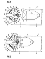
- Press device (1) has a device frame (2), which is in one underside web (3) and a rounded top tool (4) continues.
- a lower tool (5) is on the device frame (2) movable translationally in the directions of the double arrow A. guided.
- the lower tool (5) is not closer to one here shown drive device in connection.
- a drive device as Hydraulic cylinder assembly formed, with the help of that Lower tool (5) can be moved.
- the lower tool (5) has two interconnected, opposite and firmly connected to the lower tool (5) Press jaws (6, 7), the pressing surfaces (8, 9) of which are V-shaped to one another are posed.
- Press jaws (6, 7) On the upper tool (4) there are two on the opposite side Press jaws (1 ⁇ , 11) pivotally mounted about the axes (12, 13).
- the pressing jaws (1 ⁇ , 11) have convexly shaped pressing surfaces (14, 15).
- the axes (12, 13) run perpendicular to Plane of the drawing.
- the press jaws (1 ⁇ , 11) have extensions (16, 17), on which tension springs (18, 19) engage, the other ends are attached to pins (2 ⁇ , 21), which with the upper tool (4) are connected.
- a further press jaw (22) is attached to the upper tool (4), with a tapered part between the swiveling Press jaws (1 ⁇ , 11) extends and a concave pressing surface (23) having.
- the press jaw (22) also has a concave shape Guide surfaces (24, 25) on which the pressing surfaces (14, 15) the press jaws (1 ⁇ , 11) slide when the press jaws (1 ⁇ , 11) from their starting position shown in Figure (1) in the Press position according to Figure (3) are pivoted.
- the opened pressing device (1) As shown in Figure (1), a conductor (26) with put on, sleeve-shaped cable lug (27) between the Press jaws (1 ⁇ , 11) of the upper tool (4) inserted. Then it will be the lower tool with the help of the drive device in the direction moved to the upper tool (4).
- the press jaws (6, 7) of the lower tool (5) come to rest on the cable lug (27), butt their pressing surfaces (8, 9) against projections (28, 29) Press jaws (1 ⁇ , 11).
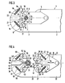
- the pressing device (31) shown in Figures (4) to (6) has a device frame (32), which is in an underside web (33) and a rounded top tool (34) continues.
- a lower tool (35) movable translationally in the directions of the double arrow B. guided.
- the lower tool is also here with a Drive device, not shown, e.g. in shape a hydraulic cylinder arrangement or an electric motor, in Connection.
- the lower tool (35) has two opposing press jaws (36, 37), which - in contrast to the exemplary embodiment according to Figures (1) to (3) - pivotable about axes (38, 39) are stored.
- the press jaws (36, 37) have flat press surfaces (4 ⁇ , 41). They have extensions (42, 43) on which tension springs (44, 45) attack, the other ends on pins (46, 47) are attached, which are connected to the lower tool (35) are.
- a further press jaw (48) is on the lower tool (35) attached with a tapered part between the swiveling press jaws (4 ⁇ , 41) and also extends has flat pressing surface (49).
- the other press jaw (48) has concave guide surfaces (5 ⁇ , 51) on which the pressing surfaces (4 ⁇ , 41) adjoining sections of the press jaws (36, 37) slide past when the press jaws (36, 37) come out of their in figure (4) shown starting position in the pressing position according to Figure (6) can be pivoted.
- the upper tool (34) is essentially identical to that Upper tool (4) of the exemplary embodiment according to the figures (1) to (3) and otherwise mirror image of the lower tool (35) trained. It has accordingly pivotable about axes (52, 53) stored press jaws (54, 55) with flat press surfaces (56, 57). Tension springs (6 ⁇ , 61) engage on extensions (58, 59), which are connected to the upper tool (34) via pins (62, 63).
- she has concave guide surfaces (66, 67) on which the press jaws (56, 57) slide.
- the pressing process runs essentially like that Embodiment according to Figures (1) to (3).
- the opened pressing device (31) becomes a combination of conductors (68) and sleeve-shaped cable lug (69) inserted.
- the lower tool (35) in the direction of the upper tool (34) moves. If the pressing surfaces (4 ⁇ , 41) or (56, 57) of the press jaws (36, 37) or (54, 55) on the Cable lug (69) come into contact, protrusions (7 ⁇ , 71, 72, 73) on the press jaws (36, 37, 54, 55). It The actual pressing process then begins.
Landscapes
- Engineering & Computer Science (AREA)
- Mechanical Engineering (AREA)
- Manufacturing & Machinery (AREA)
- Manufacturing Of Electrical Connectors (AREA)
- Processing Of Terminals (AREA)
- Insertion, Bundling And Securing Of Wires For Electric Apparatuses (AREA)
- Installation Of Indoor Wiring (AREA)
- Press Drives And Press Lines (AREA)
Description
- Figur (1)
- ein Preßgerät gemäß der Erfindung in Ausgangsstellung;
- Figur (2)
- das Preßgerät gemäß Figur (1) zu Beginn des Preßvorgangs;
- Figur (3)
- das Preßgerät gemäß den Figuren (1) und (2) am Ende des Preßvorgangs;
- Figur (4)
- ein anderes Preßgerät nach der Erfindung in Ausgangsstellung;
- Figur (5)
- das Preßgerät gemäß Figur (4) zu Beginn des Preßvorgangs und
- Figur (6)
- das Preßgerät gemäß den Figuren (4) und (5) am Ende des Preßvorgangs.
Claims (11)
- Preßgerät (1, 31) zum Aufpressen von Hülsen (27), Kabelschuhen (27, 69) oder dergleichen auf ein Werkstück (26), mit zwei Werkzeugen (4, 5; 34, 35), die mit Hilfe einer Antriebseinrichtung unter Bildung eines Preßraumes zusammenführbar sind, wobei jedes Werkzeug (4, 5; 34, 35) Preßbacken (6, 7, 1⊘, 11; 36, 37, 54, 55) aufweist, deren Preßflächen (8, 9, 14, 15; 4⊘, 41, 56, 57) derart geformt sind, daß sich beim Verpressen eine Polygonform ergibt,
gekennzeichnet durch folgende Merkmale:a) wenigstens ein Werkzeug (4, 34, 35) weist gegenüberliegend zwei spiegelbildlich angeordnete, schwenkbare Preßbacken (1⊘, 11; 36, 37, 54, 55) auf;b) die Schwenkachsen (12, 13; 38, 39, 52, 53) der Preßbacken (1⊘, 11; 36, 37, 54, 55) eines Werkzeuges (4; 34, 35) liegen jeweils in einer Ebene, welche sich - gesehen von dem zugehörigen Werkzeug (4; 34, 35) - diesseits des Preßraums erstreckt;c) gegen die schwenkbaren Preßbacken (1⊘, 11; 36, 37, 54, 55) des einen Werkzeugs (4, 34, 35) ist das andere Werkzeug (5, 34, 35) beim Zusammenführen der Werkzeuge (4, 5; 34, 35) unter Verschwenkung aus einer Ausgangsstellung in eine den Preßraum ausbildende Preßstellung anfahrbar. - Preßgerät nach Anspruch (1),
dadurch gekennzeichnet, daß das andere Werkzeug (5) unbewegliche Preßbacken (6, 7) aufweist. - Preßgerät nach Anspruch (1),
dadurch gekennzeichnet, daß beide Werkzeuge (34, 35) jeweils zwei gegenüberliegende, spiegelbildlich angeordnete, schwenkbare Preßbacken (36, 37, 54, 55) aufweisen, deren Schwenkachsen jeweils in einer Ebene liegen, welche sich - gesehen von dem jeweils zugehörigen Werkzeug (4; 34, 35) - diesseits des Preßraums erstrecken. - Preßgerät nach einem der Ansprüche (1) bis (3),
dadurch gekennzeichnet, daß die verschwenkbaren Preßbacken (1⊘, 11; 36, 37, 54, 55) über Schwenkachsen (12, 13; 38, 39, 52, 53) gelagert sind. - Preßgerät nach einem der Ansprüche (1) bis (4),
dadurch gekennzeichnet, daß die verschwenkbaren Preßbacken (1⊘, 11; 36, 37, 54, 55) an Führungsbahnen (24, 25; 5⊘, 51, 66, 67) anliegend geführt sind. - Preßgerät nach einem der Ansprüche (1) bis (5),
dadurch gekennzeichnet, daß beim Zusammenfahren der Werkzeuge (4, 5; 34, 35) die Preßbacken (6, 7, 1⊘, 11; 36, 37, 54, 55) gegeneinander anfahren. - Preßgerät nach einem der Ansprüche (1) bis (6)
dadurch gekennzeichnet, daß die verschwenkbaren Preßbacken (1⊘, 11; 36, 37, 54, 55) in Richtung auf die Ausgangsstellung federbeaufschlagt sind. - Preßgerät nach einem der Ansprüche (1) bis (7),
dadurch gekennzeichnet, daß zwischen den verschwenkbaren Preßbacken (1⊘, 11; 36, 37, 54, 55) eines bzw. beider Werkzeuge (4; 34, 35) jeweils eine weitere, gegenüber diesen unbewegliche Preßbacke (22, 64) angeordnet ist. - Preßgerät nach Anspruch (8),
dadurch gekennzeichnet, daß jeweils die verschwenkbaren Preßbacken (1⊘, 11; 36, 37, 54, 55) und die demgegenüber unbewegliche Preßbacke (22; 48, 64) eines Preßwerkzeuges (4; 34, 35) derart aneinander angepaßt sind, daß die verschwenkbaren Preßbacken (1⊘, 11; 36, 37, 54, 55) die unbewegliche Preßbacke (22, 48, 64) über den Schwenkbereich führen. - Preßgerät nach einem der Ansprüche (1) bis (9),
dadurch gekennzeichnet, daß die verschwenkbaren Preßbacken (36, 37, 54, 55) ebene Preßflächen (4⊘, 41, 56, 57) aufweisen. - Preßgerät nach einem der Ansprüche (1) bis (1⊘),
dadurch gekennzeichnet, daß die verschwenkbaren Preßbacken (1⊘, 11) konvexe Preßflächen (14, 15) aufweisen.
Applications Claiming Priority (2)
| Application Number | Priority Date | Filing Date | Title |
|---|---|---|---|
| DE9217886U | 1992-12-31 | ||
| DE9217886U DE9217886U1 (de) | 1992-12-31 | 1992-12-31 | Preßgerät zum Aufpressen von Hülsen, Kabelschuhpressen o.dgl. |
Publications (2)
| Publication Number | Publication Date |
|---|---|
| EP0604828A1 EP0604828A1 (de) | 1994-07-06 |
| EP0604828B1 true EP0604828B1 (de) | 1998-09-02 |
Family
ID=6887717
Family Applications (1)
| Application Number | Title | Priority Date | Filing Date |
|---|---|---|---|
| EP93120183A Expired - Lifetime EP0604828B1 (de) | 1992-12-31 | 1993-12-15 | Pressgerät zum Aufpressen von Hülsen, Kabelschuhpressen oder dergleichen |
Country Status (7)
| Country | Link |
|---|---|
| US (1) | US5644944A (de) |
| EP (1) | EP0604828B1 (de) |
| JP (1) | JPH076847A (de) |
| AT (1) | ATE170674T1 (de) |
| AU (1) | AU670837B2 (de) |
| DE (2) | DE9217886U1 (de) |
| NO (1) | NO934906L (de) |
Families Citing this family (4)
| Publication number | Priority date | Publication date | Assignee | Title |
|---|---|---|---|---|
| DE19533054C1 (de) * | 1995-09-07 | 1997-01-09 | Novopress Gmbh | Verfahren zum Verbinden von seil- oder kabelartigen Strängen mit Verbindungsorganen sowie Preßgerät zur Durchführung dieses Verfahrens |
| US6035521A (en) * | 1997-11-18 | 2000-03-14 | General Motors Corporation | Multi-directional crimp plate |
| US6016682A (en) * | 1998-08-11 | 2000-01-25 | Ethicon, Inc. | Swaging apparatus for surgical needles |
| KR102115883B1 (ko) * | 2020-01-07 | 2020-05-27 | 도준희 | 압착기에 사용되는 압착 헤드 |
Family Cites Families (19)
| Publication number | Priority date | Publication date | Assignee | Title |
|---|---|---|---|---|
| US1850679A (en) * | 1929-02-26 | 1932-03-22 | Johnson Bronze Co | Process and apparatus for forming bushings |
| AT137643B (de) * | 1933-04-04 | 1934-05-25 | Peter Binder | Vorrichtung zur Herstellung von Verbindungshülsen, insbesondere für die überlappenden Enden von Kistenbändern. |
| US2541544A (en) * | 1946-07-19 | 1951-02-13 | Valiton Richardson Inc | Compressing machine having two pivoted dies closed by reciprocating mount for third die |
| DE1059525B (de) * | 1957-04-12 | 1959-06-18 | Frieseke & Hoepfner Gmbh | Hydraulische Druckpresse zum Befestigen eines elektrischen Huelsenverbinders auf einem Leiter |
| NL262565A (de) * | 1960-03-21 | |||
| AT232350B (de) * | 1960-10-22 | 1964-03-10 | Boehler & Co Ag Geb | Verfahren zum Streckschmieden, insbesondere von Gußblöcken aus schwer verformbaren Metall- und Stahllegierungen, unter Verwendung von Winkelsätteln |
| US3245246A (en) * | 1961-12-18 | 1966-04-12 | Positive Connector Co | Method and apparatus for assembling terminals and wires |
| US3575036A (en) * | 1967-09-13 | 1971-04-13 | Amp Inc | Crimping tool and die assembly |
| GB1210124A (en) * | 1968-02-14 | 1970-10-28 | Ccl Systems Ltd | Improved device for attaching metal fittings to electrical conductors or other cables |
| US3756064A (en) * | 1972-03-24 | 1973-09-04 | Waldes Kohinoor Inc | Hand-operated plier-like tools |
| DE2626919A1 (de) * | 1976-06-16 | 1977-12-29 | Schuitemaker Mach Bv | Verfahren zur herstellung von gelenken, vorrichtung zur durchfuehrung dieses verfahrens und gelenk, hergestellt gemaess diesem verfahren |
| US4048839A (en) * | 1976-10-14 | 1977-09-20 | Thomas & Betts Corporation | Die means having workpiece releasing means |
| US4304116A (en) * | 1979-12-07 | 1981-12-08 | Rheem Manufacturing Company | Multi-part die assembly for forming a closed clip |
| US4604890A (en) * | 1982-02-08 | 1986-08-12 | Teledyne Penn-Union | Compression tool |
| DE3235040C2 (de) * | 1982-09-22 | 1984-12-06 | Helmut Dipl.-Ing. 4040 Neuss Dischler | Presse zum Aufpressen von Hülsen, Kabelschuhen oder dergleichen |
| DE8402284U1 (de) * | 1984-01-27 | 1984-06-07 | Schmidt, Dieter, 5064 Rösrath | Automatischer Bandvorschub für Handcrimpzange |
| US4723434A (en) * | 1984-10-29 | 1988-02-09 | Square D Company | Centering device for hydraulic compression tools |
| US4732434A (en) * | 1986-09-29 | 1988-03-22 | Metalworks, Inc. | Horizontal file drawer interlock assembly |
| DE8704860U1 (de) * | 1987-04-01 | 1987-09-17 | Dischler, Helmut, Dipl.-Ing., 4040 Neuss | Vorrichtung zum Aufpressen einer Hülse auf ein Werkstück |
-
1992
- 1992-12-31 DE DE9217886U patent/DE9217886U1/de not_active Expired - Lifetime
-
1993
- 1993-12-15 EP EP93120183A patent/EP0604828B1/de not_active Expired - Lifetime
- 1993-12-15 DE DE59308955T patent/DE59308955D1/de not_active Expired - Fee Related
- 1993-12-15 AT AT93120183T patent/ATE170674T1/de active
- 1993-12-28 JP JP5334774A patent/JPH076847A/ja not_active Withdrawn
- 1993-12-30 AU AU52812/93A patent/AU670837B2/en not_active Ceased
- 1993-12-30 NO NO934906A patent/NO934906L/no unknown
-
1995
- 1995-12-11 US US08/570,190 patent/US5644944A/en not_active Expired - Fee Related
Also Published As
| Publication number | Publication date |
|---|---|
| NO934906L (no) | 1994-07-01 |
| AU670837B2 (en) | 1996-08-01 |
| DE9217886U1 (de) | 1993-02-25 |
| EP0604828A1 (de) | 1994-07-06 |
| NO934906D0 (no) | 1993-12-30 |
| JPH076847A (ja) | 1995-01-10 |
| AU5281293A (en) | 1994-07-14 |
| ATE170674T1 (de) | 1998-09-15 |
| DE59308955D1 (de) | 1998-10-08 |
| US5644944A (en) | 1997-07-08 |
Similar Documents
| Publication | Publication Date | Title |
|---|---|---|
| EP0468335B1 (de) | Werkzeug zum Crimpen eines Verbinders mit einem Leiter einerseits und einer Isolierung andererseits | |
| DE2711063C2 (de) | Handpreßwerkzeug | |
| DE3423283C2 (de) | ||
| EP0540880B1 (de) | Zange zum Bearbeiten von Leiterenden | |
| DE2018901C3 (de) | Werkzeug zum Andrücken eines im Querschnitt im wesentlichen Uförmigen elektrischen Verbinders an einen Leiter | |
| DE1909716A1 (de) | Biegsamer Staender | |
| EP1273939A2 (de) | Verfahren und Zange zum Schneiden amorpher Lichtwellenleiterkabel | |
| DE60305144T2 (de) | Einheit zur Spannkraftverstärkung für einen Schraubstock | |
| DE102018121971A1 (de) | Presswerkzeug | |
| DE69200974T2 (de) | Punktschweisszange. | |
| EP0604828B1 (de) | Pressgerät zum Aufpressen von Hülsen, Kabelschuhpressen oder dergleichen | |
| DE102007032584B4 (de) | Vorrichtung zum Schweißen einer Litze an einen Kontakt | |
| DE102020130458A1 (de) | Verbindungs-Crimpvorrichtung | |
| EP0689888B1 (de) | Blindbefestigersetzgerät | |
| DE2614577C2 (de) | Crimp-Werkzeug zum Herstellen von lötfreien permanenten elektrischen Verbindungen | |
| EP1045499A1 (de) | Zange | |
| DE2738238A1 (de) | Schweissmaschine | |
| EP0583223B1 (de) | Crimpwerkzeug für elektrische Stecker und Verwendung desselben | |
| DE2521378A1 (de) | Zange zum verpressen von kabelverbindern (crimp-werkzeug) | |
| DE19539580B4 (de) | Presszange zum Verpressen von Kontaktelementen | |
| DE1906102C (de) | Hydraulisch betatigbare Vorrichtung zur Herstellung einer elektrischen Preß verbindung | |
| DE1958830U (de) | Zange zur herstellung einer sechskantpressung an elektrischen leitern u. dgl. | |
| DE2243443C3 (de) | Vorrichtung zum Herauspressen und Abscheren der wärmebeeinflussten Zonen an einer Stumpfschweissverbindung von zwei länglichen Werkstücken | |
| EP1199780B1 (de) | Abisolierwerkzeug | |
| EP2051342A2 (de) | Preßstempel für ein Kabel-Crimpwerkzeug |
Legal Events
| Date | Code | Title | Description |
|---|---|---|---|
| PUAI | Public reference made under article 153(3) epc to a published international application that has entered the european phase |
Free format text: ORIGINAL CODE: 0009012 |
|
| AK | Designated contracting states |
Kind code of ref document: A1 Designated state(s): AT BE CH DE DK ES FR IT LI NL SE |
|
| 17P | Request for examination filed |
Effective date: 19940616 |
|
| 17Q | First examination report despatched |
Effective date: 19950228 |
|
| GRAG | Despatch of communication of intention to grant |
Free format text: ORIGINAL CODE: EPIDOS AGRA |
|
| GRAG | Despatch of communication of intention to grant |
Free format text: ORIGINAL CODE: EPIDOS AGRA |
|
| GRAH | Despatch of communication of intention to grant a patent |
Free format text: ORIGINAL CODE: EPIDOS IGRA |
|
| GRAH | Despatch of communication of intention to grant a patent |
Free format text: ORIGINAL CODE: EPIDOS IGRA |
|
| GRAA | (expected) grant |
Free format text: ORIGINAL CODE: 0009210 |
|
| AK | Designated contracting states |
Kind code of ref document: B1 Designated state(s): AT BE CH DE DK ES FR IT LI NL SE |
|
| PG25 | Lapsed in a contracting state [announced via postgrant information from national office to epo] |
Ref country code: NL Free format text: LAPSE BECAUSE OF FAILURE TO SUBMIT A TRANSLATION OF THE DESCRIPTION OR TO PAY THE FEE WITHIN THE PRESCRIBED TIME-LIMIT Effective date: 19980902 Ref country code: ES Free format text: THE PATENT HAS BEEN ANNULLED BY A DECISION OF A NATIONAL AUTHORITY Effective date: 19980902 |
|
| REF | Corresponds to: |
Ref document number: 170674 Country of ref document: AT Date of ref document: 19980915 Kind code of ref document: T |
|
| REG | Reference to a national code |
Ref country code: CH Ref legal event code: EP |
|
| REF | Corresponds to: |
Ref document number: 59308955 Country of ref document: DE Date of ref document: 19981008 |
|
| ET | Fr: translation filed | ||
| PG25 | Lapsed in a contracting state [announced via postgrant information from national office to epo] |
Ref country code: DK Free format text: LAPSE BECAUSE OF FAILURE TO SUBMIT A TRANSLATION OF THE DESCRIPTION OR TO PAY THE FEE WITHIN THE PRESCRIBED TIME-LIMIT Effective date: 19981202 |
|
| PG25 | Lapsed in a contracting state [announced via postgrant information from national office to epo] |
Ref country code: AT Free format text: LAPSE BECAUSE OF NON-PAYMENT OF DUE FEES Effective date: 19981215 |
|
| PG25 | Lapsed in a contracting state [announced via postgrant information from national office to epo] |
Ref country code: LI Free format text: LAPSE BECAUSE OF NON-PAYMENT OF DUE FEES Effective date: 19981231 Ref country code: CH Free format text: LAPSE BECAUSE OF NON-PAYMENT OF DUE FEES Effective date: 19981231 Ref country code: BE Free format text: LAPSE BECAUSE OF NON-PAYMENT OF DUE FEES Effective date: 19981231 |
|
| NLV1 | Nl: lapsed or annulled due to failure to fulfill the requirements of art. 29p and 29m of the patents act | ||
| BERE | Be: lapsed |
Owner name: DISCHLER HELMUT Effective date: 19981231 |
|
| PLBE | No opposition filed within time limit |
Free format text: ORIGINAL CODE: 0009261 |
|
| STAA | Information on the status of an ep patent application or granted ep patent |
Free format text: STATUS: NO OPPOSITION FILED WITHIN TIME LIMIT |
|
| REG | Reference to a national code |
Ref country code: CH Ref legal event code: PL |
|
| 26N | No opposition filed | ||
| PGFP | Annual fee paid to national office [announced via postgrant information from national office to epo] |
Ref country code: DE Payment date: 20011220 Year of fee payment: 9 |
|
| PGFP | Annual fee paid to national office [announced via postgrant information from national office to epo] |
Ref country code: SE Payment date: 20020124 Year of fee payment: 9 Ref country code: FR Payment date: 20020124 Year of fee payment: 9 |
|
| PG25 | Lapsed in a contracting state [announced via postgrant information from national office to epo] |
Ref country code: SE Free format text: LAPSE BECAUSE OF NON-PAYMENT OF DUE FEES Effective date: 20021216 |
|
| PG25 | Lapsed in a contracting state [announced via postgrant information from national office to epo] |
Ref country code: DE Free format text: LAPSE BECAUSE OF NON-PAYMENT OF DUE FEES Effective date: 20030701 |
|
| EUG | Se: european patent has lapsed | ||
| PG25 | Lapsed in a contracting state [announced via postgrant information from national office to epo] |
Ref country code: FR Free format text: LAPSE BECAUSE OF NON-PAYMENT OF DUE FEES Effective date: 20030901 |
|
| REG | Reference to a national code |
Ref country code: FR Ref legal event code: ST |
|
| PG25 | Lapsed in a contracting state [announced via postgrant information from national office to epo] |
Ref country code: IT Free format text: LAPSE BECAUSE OF NON-PAYMENT OF DUE FEES;WARNING: LAPSES OF ITALIAN PATENTS WITH EFFECTIVE DATE BEFORE 2007 MAY HAVE OCCURRED AT ANY TIME BEFORE 2007. THE CORRECT EFFECTIVE DATE MAY BE DIFFERENT FROM THE ONE RECORDED. Effective date: 20051215 |