EP0604681B1 - Nozzleboom for raining upon especially agricultural surfaces - Google Patents
Nozzleboom for raining upon especially agricultural surfaces Download PDFInfo
- Publication number
- EP0604681B1 EP0604681B1 EP92122123A EP92122123A EP0604681B1 EP 0604681 B1 EP0604681 B1 EP 0604681B1 EP 92122123 A EP92122123 A EP 92122123A EP 92122123 A EP92122123 A EP 92122123A EP 0604681 B1 EP0604681 B1 EP 0604681B1
- Authority
- EP
- European Patent Office
- Prior art keywords
- boom
- nozzle
- scissor
- lazy
- tongs
- Prior art date
- Legal status (The legal status is an assumption and is not a legal conclusion. Google has not performed a legal analysis and makes no representation as to the accuracy of the status listed.)
- Expired - Lifetime
Links
Images


Classifications
-
- A—HUMAN NECESSITIES
- A01—AGRICULTURE; FORESTRY; ANIMAL HUSBANDRY; HUNTING; TRAPPING; FISHING
- A01G—HORTICULTURE; CULTIVATION OF VEGETABLES, FLOWERS, RICE, FRUIT, VINES, HOPS OR SEAWEED; FORESTRY; WATERING
- A01G25/00—Watering gardens, fields, sports grounds or the like
- A01G25/09—Watering arrangements making use of movable installations on wheels or the like
Definitions
- the invention relates to a nozzle boom for the irrigation of agricultural areas in particular, which is arranged on a chassis and is variable in length, the nozzles being connected to a main water line via feed lines, and the boom being designed as a scissor element which can be actuated by means of a drive device .
- the nozzle booms consist of a spatial or flat framework construction which is arranged on a chassis with which it is moved in a linear direction over the arable area to be irrigated.
- the chassis is connected to a water pipe of the main water pipe which is laid in the direction of movement of the nozzle boom and which is connected at the other end to an irrigation machine.
- the latter has a drum on which the water pipe is wound when the drum is rotated.
- Previously known nozzle booms consist of frameworks that can be collapsed or telescoped, some of which are in the first stage hydraulically unfolded and then unfolded further by hand. Despite everything, the operations involved are still time consuming. As a rule, two workers are required for this.
- the object of the invention is to provide a nozzle boom of the type mentioned, which can be opened comparatively quickly and with a single worker and brought into operational readiness and folded in the same way back into its transport position, but large spans are to be achieved.
- This object is achieved according to the invention in that at least two scissor elements are arranged substantially congruently at a distance above one another, which are connected to one another by means of tensioning and supporting elements.
- This design according to the invention leads to a mechanically very stable construction of the nozzle arm. It roughly corresponds to a spatial structure. With this design, spans of the nozzle boom according to the invention of approximately 40 to approximately 60 m are possible.
- two scissor elements arranged one above the other are provided symmetrically on the two sides of the chassis running parallel to the direction of travel of the nozzle aligner. From mechanical-structural considerations it follows that this two-part construction enables the maximum possible span of the nozzle boom. In this case too, only a single drive device is required, which will usually be a cable winch or a water-hydraulic-operated liquid motor. The liquid motor can be connected to the water supply system of the water to be distributed.
- the scissor element (s) are mounted on the chassis so that they can be pivoted horizontally.
- the nozzle arm can also perform an oscillating pivoting movement. In this way, during the time unit of the water to be discharged, it is distributed over two partial circles or circular segments, the area of which is far larger than the strip which can be irrigated by means of a nozzle arm arranged rigidly on the chassis. This means that the water released has a longer time to penetrate into the soil. The soil can absorb the water. Puddle formation is avoided.
- the device according to the invention basically consists of a nozzle arm 4 and a chassis 1.
- the chassis 1 has wheels 2 with which the nozzle arm 4 can be moved. As a rule, this is done via a hose line laid on the floor, through which water is fed to the nozzle arm.
- the hose line is connected in the area of the chassis 1 to supply lines which are arranged on the boom 4 and supply nozzles 5 with water which is discharged onto the floor in the manner indicated. Hose lines and supply lines are not shown since they are known devices in connection with the technology described here.
- the hose line laid on the floor is attached to the drum of an irrigation machine at the other end. If the drum is set in rotation, the hose line simultaneously acts as a pulling element for moving the nozzle arm 4 over the agricultural area to be irrigated.
- the nozzle arm 4 is designed as a scissor element.
- Two first scissor parts 4.1 are articulated on a bearing axis 3 of the chassis 1.
- second scissor parts 4.2 which are connected to one another at the articulation point 7, are in turn articulated at the ends of the scissor parts 4.1.
- scissor parts 4.3 are again articulated to the scissor parts 4.2.
- a scissor part 4.4 ends in the region of the articulation point 8. A continuation is not necessary since the desired width of the nozzle arm 4 is achieved with the double length of the other scissor part 4.3.
- a drive device 6 is provided on the scissor parts 4.1 articulated on the bearing axis 3. In the embodiment according to FIGS. 1 and 2, this is a cable winch.
- a cable 9 is guided to the corresponding scissor part 4.1 on the same side with respect to the bearing axis 3.
- Another cable 10 also leads to the corresponding scissor part 4.1, but on the side opposite the bearing axis.
- the nozzle arm 4 is extended into the extended position shown in FIGS. 1 and 2. However, if the cable 10 is shortened, so the nozzle arm 4 is retracted or folded.
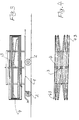
- the nozzle boom 4 is shown in its folded state in FIGS. 3 and 4.
- the representation selected in FIG. 4 shows the nozzle boom 4 alone, that is to say without the chassis 1 etc. in its retracted state.
- two scissor parts 4.1 to 4.3 are provided congruently at a distance from one another.
- the respective scissor parts corresponding to each other are connected to each other with tendons or support members.
- a spatially extended scissor construction is obtained which has increased mechanical strength. In this way it is possible to achieve spans of approximately 40 to approximately 60 m of the entire nozzle boom.
- the boom 4 is arranged to carry out a horizontal pendulum movement on the bearing axis 3.
- the boom 4 can be pivoted alternately from its basic position shown in solid lines into the end positions shown in dashed lines during its linear movement, as a result of which the water to be rained is spread over a larger area per unit of time than that with an exclusively linear movement of the nozzle arm 4 is the case.
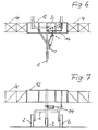
- FIG. 6 and 7 show details of the drive device for this pendulum movement according to FIG. 5 again.
- a central part 12 forms an integral part of the nozzle arm 4. These two parts are firmly connected to one another.
- the piston tappet is extended or retracted, the strut 14 and thus the boom 4 being pivoted about its bearing axis 3, specifically in the top view in FIG. 6 positions shown on the device.
- the desired pendulum movement according to FIG. 5 is effected with a reciprocating piston tappet.
Abstract
Description
Die Erfindung bezieht sich auf einen Düsenausleger für die Beregnung insbes. landwirtschaftlicher Flächen, der auf einem Fahrgestell angeordnet und längenveränderlich ausgebildet ist, wobei die Düsen ber Zuleitungen mit einer Wasserhauptleitung verbunden sind, und der Ausleger als Scherenelement ausgebildet ist, das mittels einer Antriebseinrichtung betätigbar ist.The invention relates to a nozzle boom for the irrigation of agricultural areas in particular, which is arranged on a chassis and is variable in length, the nozzles being connected to a main water line via feed lines, and the boom being designed as a scissor element which can be actuated by means of a drive device .
Zur Beregnung landwirtschaftlicher Flächen, einschließlich Gartenbauflächen od. dgl. ist es bekannt, Düsenausleger zu benutzen, um Wasser möglichst genau verteilt, sparsam sowie auch energiesparend auf die zu beregnenden Flächen aufzubringen. Die Düsenausleger bestehen in der Regel aus einer räumlichen oder flächigen Fachwerkkonstruktion, die an einem Fahrgestell angeordnet ist, mit dem sie über die zu beregnende Ackerfläche in linearer Richtung bewegt wird. Das Fahrgestell ist hierbei an einer in der Bewegungsrichtung des Düsenauslegers verlegten Wasserleitung der Wasserhauptleitung angeschlossen, die andernends mit einer Beregungsmaschine verbunden ist. Letztere weist eine Trommel auf, auf die die Waserleitung aufgewickelt wird, wenn die Trommel in Drehung versetzt wird. Hierdurch wird die Länge der zuvor ausgelegten Wasserleitung langsam verkürzt, so daß der Düsenausleger über die landwirtschaftliche Fläche ebenso langsam bewegt wird. Auf diese Weise kommt es zu einer gleichmäßigen Beregnung durch das durch die Wasserhauptleitung und die Zuleitungen in die Düsen strömenden und dort austretenden Wassers.For irrigation of agricultural areas, including horticultural areas or the like, it is known to use nozzle brackets in order to distribute water as precisely as possible, sparingly and also in an energy-saving manner to the areas to be irrigated. As a rule, the nozzle booms consist of a spatial or flat framework construction which is arranged on a chassis with which it is moved in a linear direction over the arable area to be irrigated. The chassis is connected to a water pipe of the main water pipe which is laid in the direction of movement of the nozzle boom and which is connected at the other end to an irrigation machine. The latter has a drum on which the water pipe is wound when the drum is rotated. As a result, the length of the previously designed water pipe is slowly shortened, so that the nozzle boom is also moved slowly over the agricultural area. In this way, there is a uniform irrigation due to the water flowing through the main water line and the feed lines into the nozzles and exiting there.
Bisher bekannte Düsenausleger bestehen aus mehrfach zusammenklappbaren oder teleskopisch ineinander schiebbaren Rahmenwerken, die teilweise in der ersten Stufe hydraulisch ausgeklappt und dann von Hand weiter aufgefaltet werden. Trotz allem sind die hiermit verbundenen Arbeitsgänge immer noch zeitaufwendig. In aller Regel sind hierzu zwei Arbeitskräfte erforderlich.Previously known nozzle booms consist of frameworks that can be collapsed or telescoped, some of which are in the first stage hydraulically unfolded and then unfolded further by hand. Despite everything, the operations involved are still time consuming. As a rule, two workers are required for this.
Aus WO-A-8302713 sind scherenartige Düsenaufleger bekannt. Aufgrund des im wesentlichen zweidimensionalen Aufbaus dieser Ausleger neigen sie im ausgefahrenen Zustand zur Deformation, weshalb mit ihnen nur begrenzte Spannweiten erreicht werden können.From WO-A-8302713 scissor-like nozzle applicators are known. Due to the essentially two-dimensional structure of these booms, they tend to deform when extended, which is why only limited spans can be achieved with them.
Die Aufgabe der Erfindung besteht darin, einen Düsenausleger der eingangs genannten Art zu schaffen, der vergleichsweise schnell und mit einer einzigen Arbeitskraft auseinandergeklappt und in Betriebsbereitschaft gebracht und auf ebensolche Weise umgekehrt wieder in seine Transportstellung zusammengefaltet werden kann, wobei jedoch große Spannweiten erzielt werden sollen.The object of the invention is to provide a nozzle boom of the type mentioned, which can be opened comparatively quickly and with a single worker and brought into operational readiness and folded in the same way back into its transport position, but large spans are to be achieved.
Diese Aufgabe wird gemäß der Erfindung dadurch gelöst, daß mindestens zwei Scherenelemente im wesentlichen deckungsgleich mit Abstand übereinander angeordnet sind, die mittels Spann- und Stützelementen miteinander verbunden sind. Diese erfindungsgemäße Ausbildung führt zu einer mechanisch sehr stabilen Konstruktion des Düsenauslegers. Sie entspricht in etwa einem räumlichen Tragwerk. Mit dieser Ausbildung sind Spannweiten des erfindungsgemäßen Düsenauslegers von etwa 40 bis etwa 60 m möglich.This object is achieved according to the invention in that at least two scissor elements are arranged substantially congruently at a distance above one another, which are connected to one another by means of tensioning and supporting elements. This design according to the invention leads to a mechanically very stable construction of the nozzle arm. It roughly corresponds to a spatial structure. With this design, spans of the nozzle boom according to the invention of approximately 40 to approximately 60 m are possible.
Es kann nicht nur eine zweiteilige, sondern auch eine mehrteilige Schere gemäß der Erfindung verwendet werden. Auch bei Einsatz eines solchen mehrteiligen Scherenelementes mit räumlichen Tragwerken ist es einer einzigen Bedienungsperson möglich, daß Scherenelement, also den gesamten Düsenausleger auszufahren und auch wieder einzuklappen. Dies geschieht über ein Antriebseinrichtung, die an einem einzigen zweiteiligen Scherenelement angreift. Da die Bauteile des Scherenelementes miteinander verbunden sind, wird die Bewegung des einen Scherenteiles auf das gesamte Scherenelement übertragen.Not only two-part scissors but also multi-part scissors according to the invention can be used. Even when using such a multi-part scissor element with spatial structures, it is possible for a single operator to extend the scissor element, that is to say the entire nozzle arm, and also to fold it in again. This is done via a drive device that engages a single two-part scissor element. Since the components of the scissor element are connected to one another, the movement of one scissor part is transmitted to the entire scissor element.
Nach einem weiteren Merkmal der Erfindung ist vorgesehen, daß je zwei übereinander angeordnete Scherenelemente symmetrisch an den beiden parallel zur Fahrtrichtung des Düsenausrichters verlaufenden Seiten des Fahrgestells vorgesehen sind. Aus mechanisch-konstruktiven Überlegungen folgt, daß mit dieser zweiteiligen Konstruktion die maximal mögliche Spannweite des Düsenauslegers ermöglicht wird. Auch in diesem Falle ist nur eine einzige Antriebsvorrichtung erforderlich, die in der Regel eine Seilwinde oder ein wasserhydraulisch betätigter Flüssigkeitsmotor sein wird. Der Flüssigkeitsmotor kann an das Wasserversorgungssystem des zu verteilenden Wasser angeschlossen sein.According to a further feature of the invention it is provided that two scissor elements arranged one above the other are provided symmetrically on the two sides of the chassis running parallel to the direction of travel of the nozzle aligner. From mechanical-structural considerations it follows that this two-part construction enables the maximum possible span of the nozzle boom. In this case too, only a single drive device is required, which will usually be a cable winch or a water-hydraulic-operated liquid motor. The liquid motor can be connected to the water supply system of the water to be distributed.
Schließlich liegt es noch im Rahmen der Erfindung, wenn das bzw. die Scherenelemente horizontal verschwenkbar am Fahrgestell gelagert sind. Hierdurch kann der Düsenausleger zusätzlich zu seiner Linearbewegung noch eine pendelnde Schwenkbewegung ausführen. Auf diese Weise wird während der Zeiteinheit des auszubringende Wasser über zwei Teilkreise oder Kreissegmente verteilt, deren Fläche weitaus größer als der Streifen ist, der mittels eines starr am Fahrgestell angeordneten Düsenauslegers bewässerbar ist. Somit steht dem ausgebrachten Wasser eine größere Zeit zum Eindringen in den Boden zur Verfügung. Der Boden kann das Wasser aufnehmen. Pfützenbildung wird vermieden.Finally, it is still within the scope of the invention if the scissor element (s) are mounted on the chassis so that they can be pivoted horizontally. As a result, in addition to its linear movement, the nozzle arm can also perform an oscillating pivoting movement. In this way, during the time unit of the water to be discharged, it is distributed over two partial circles or circular segments, the area of which is far larger than the strip which can be irrigated by means of a nozzle arm arranged rigidly on the chassis. This means that the water released has a longer time to penetrate into the soil. The soil can absorb the water. Puddle formation is avoided.
Weitere Einzelheiten, Merkmale und Vorteile der Erfindung ergeben sich aus der folgenden Beschreibung mehrerer Ausführungsbeispiele sowie anhand der Patentansprüche und der schematischen Zeichnung. Es zeigen:
- Fig. 1
- eine teilweise Stirnansicht des Düsenauslegers gemäß der Erfindung im ausgefahrenen Zustand;
- Fig. 2
- eine Draufsicht auf den Gegenstand der Fig. 1;
- Fig. 3
- eine Seitenansicht des Gegenstands der Fig. 1 im zusammengeklappten Zustand;
- Fig. 4
- eine teilweise Draufsicht auf den Gegenstand der Fig. 3;
- Fig. 5
- eine Draufsicht auf eine abgeänderte Ausführungsform des Gegenstandes der Fig. 1;
- Fig. 6 und 7
- Einzelheiten zur Ausführungsform nach Fig. 5.
- Fig. 1
- a partial end view of the nozzle boom according to the invention in the extended state;
- Fig. 2
- a plan view of the subject of Fig. 1;
- Fig. 3
- a side view of the object of Figure 1 in the folded state.
- Fig. 4
- a partial plan view of the subject of Fig. 3;
- Fig. 5
- a plan view of a modified embodiment of the object of Fig. 1;
- 6 and 7
- Details of the embodiment according to FIG. 5.
Gemäß Fig. 1 besteht die erfindungsgemäße Vorrichtung grundsätzlich aus einem Düsenausleger 4 und einem Fahrgestell 1. Das Fahrgestell 1 weist Räder 2 auf, mit denen der Düsenausleger 4 verfahrbar ist. In der Regel erfolgt dies über eine auf dem Boden verlegte Schlauchleitung, über die dem Düsenausleger Wasser zugeführt wird. Die Schlauchleitung ist im Bereich des Fahrgestell 1 an Zuleitungen angeschlossen, die am Ausleger 4 angeordnet sind und Düsen 5 Wasser zuführen, welches in der angedeuteten Weise auf den Boden abgegeben wird. Schlauchleitungen und Zuleitungen sind nicht dargestellt, da es sich auch in Verbindung mit der hier beschriebenen Technik um bekannte Einrichtungen handelt.1, the device according to the invention basically consists of a
Die am Boden verlegte Schlauchleitung ist andernends an der Trommel einer Beregnungsmaschine befestigt. Wird die Trommel in Drehung versetzt, so wirkt die Schlauchleitung gleichzeitig als Zugelement zur Bewegung des Düsenauslegers 4 über die zu bewässernde landwirtschaftliche Fläche.The hose line laid on the floor is attached to the drum of an irrigation machine at the other end. If the drum is set in rotation, the hose line simultaneously acts as a pulling element for moving the
Wie sich aus den Fig. 1 und 2 ergibt, ist der Düsenausleger 4 als Scherenelement ausgebildet. Zwei erste Scherenteile 4.1 sind an einer Lagerachse 3 des Fahrgestells 1 angelenkt. Wie sich insbesondere aus Fig. 2 ergibt, sind an den Enden der Scherenteile 4.1 wiederum zweite Scherenteile 4.2 angelenkt, die im Gelenkpunkt 7 miteinander verbunden sind. Andernends sind nochmals Scherenteile 4.3 an die Scherenteile 4.2 angelenkt. Wie aus Fig. 2 ersichtlich, endet ein Scherenteil 4.4 im Bereich des Gelenkpunktes 8. Eine Weiterführung ist nicht erforderlich, da mit der demgegenüber doppelten Länge des anderen Scherenteils 4.3 die gewünschte Breite des Düsenauslegers 4 erzielt ist.1 and 2, the
An den an der Lagerachse 3 angelenkten Scherenteilen 4.1 ist eine Antriebsvorrichtung 6 vorgesehen. Bei dem Ausführungsbeispiel nach den Fig. 1 und 2 ist dies eine Seilwinde. Ein Seilzug 9 ist zum korrespondierenden Scherenteil 4.1 auf der selben Seite bezüglich der Lagerachse 3 geführt. Ein weiterer Seilzug 10 führt ebenfalls zum korrespondierenden Scherenteil 4.1, jedoch auf der der Lagerachse gegenüberliegenden Seite. Wird der Seilzug 9 über die Antriebseinrichtung 6 verkürzt, so kommt es zum Ausfahren des Düsenauslegers 4 in die in den Fig. 1 und 2 gezeigte ausgefahrene Stellung. Wird hingegen der Seilzug 10 verkürzt, so wird der Düsenausleger 4 eingefahren oder eingeklappt. Der Düsenausleger 4 ist in seinem zusammengeklappten Zustand in den Fig. 3 und 4 dargestellt. Die in Fig. 4 gewählte Darstellung gibt den Düsenausleger 4 alleine, also ohne Fahrgestell 1 usw. in seinem eingefahrenen Zustand wieder.A
Wie insbesondere aus Fig. 1 ersichtlich ist, sind jeweils zwei Scherenteile 4.1 bis 4.3 deckungsgleich mit Abstand übereinander vorgesehen. Die jeweils zueinander korrespondierenden Scherenteile sind mit Spann- bzw. Stützgliedern miteinander verbunden. Auf diese Weise erhält man eine räumlich erstreckte Scherenkonstruktion, die erhöhte mechanische Festigkeit aufweist. Auf diese Weise ist es möglich, Spannweiten von etwa 40 bis etwa 60 m des gesamten Düsenauslegers zu erzielen.As can be seen in particular from FIG. 1, two scissor parts 4.1 to 4.3 are provided congruently at a distance from one another. The respective scissor parts corresponding to each other are connected to each other with tendons or support members. In this way, a spatially extended scissor construction is obtained which has increased mechanical strength. In this way it is possible to achieve spans of approximately 40 to approximately 60 m of the entire nozzle boom.
Aus der Fig. 5 ergibt sich eine Modifikation des vorstehend beschriebenen Ausführungsbeispiels. Gemäß Fig. 5 ist der Ausleger 4 zur Ausführung einer horizontalen Pendelbewegung an der Lagerachse 3 angeordnet. Mittels einer vorzugsweise wasserhydraulisch betätigten Antriebsvorrichtung kann der Ausleger 4 aus seiner durchgezogen dargestellten Grundstellung in die gestrichelt dargestellten Endstellungen während seiner Linearbewegung wechselweise verschwenkt werden, wodurch das zu verregnende Wasser auf eine größere Fläche pro Zeiteinheit ausgebracht wird, als die bei einer ausschließlich linearen Bewegung des Düsenauslegers 4 der Fall ist.5 shows a modification of the exemplary embodiment described above. 5, the
Die Fig. 6 und 7 geben Einzelheiten der Antriebsvorrichtung für diese Pendelbewegung gemäß der Fig. 5 wieder.6 and 7 show details of the drive device for this pendulum movement according to FIG. 5 again.
Wie in den Fig. 6 und 7 gezeigt, bildet ein Mittelteil 12 einen integralen Bestandteil des Düsenauslegers 4. Diese beiden Teile sind fest miteinander verbunden. Ein am Fahrgestell 1 über einen Ansatz 13 angelenkter Flüssigkeitsmotor, der über eine Zuleitung von der Wasserversorgung der Düsen des Düsenauslegers gespeist ist, ist andernends an einer Strebe 14 des Mittelteils 12 angelenkt. Bei Betätigung des Flüssigkeitsmotors, einer Kolben-Zylinder-Anordnung, kommt es zum Aus- bzw. Einfahren des Kolbenstößels, wobei die Strebe 14 und mithin der Ausleger 4 um seine Lagerachse 3 verschwenkt wird, und zwar in die in Fig. 6, einer Draufsicht auf die Vorrichtung, gezeigten Stellungen. Auf diese Weise wird die erwünschte Pendelbewegung gemäß Fig. 5 bei hin- und hergehendem Kolbenstößel bewirkt.As shown in FIGS. 6 and 7, a
Claims (5)
- Nozzle boom (4) for sprinkling agricultural areas, in particular, which is arranged on an undercarriage (1) and is of adjustable-length design, the nozzles being connected by feedlines to a main water line, and the boom (4) being designed as a lazy-tongs element (4.1 to 4.3) which can be actuated by means of a driving device, characterized in that at least two lazy-tongs elements (4.1 to 4.3) are arranged in an essentially congruent manner and at a distance apart one above the other, being connected to one another by means of tensioning and supporting elements (11).
- Boom according to Claim 1, characterized in that in each case two lazy-tongs elements (4.1 to 4.3) arranged one above the other are provided symmetrically on the two sides of the undercarriage (1) which run parallel to the direction of travel of the nozzle boom (4).
- Boom according to Claim 1 or 2, characterized in that the lazy-tongs element (4.1 to 4.3) is mounted in such a way as to be horizontally pivotable on the undercarriage (1).
- Boom according to one of Claims 1 to 3, characterized in that the driving device (6) is a cable winch.
- Boom according to Claim 1 to 3, characterized in that the driving device can be supplied with hydraulic pressure from the existing water supply.
Priority Applications (3)
| Application Number | Priority Date | Filing Date | Title |
|---|---|---|---|
| DE59207018T DE59207018D1 (en) | 1992-12-30 | 1992-12-30 | Nozzle boom for irrigation especially of agricultural areas |
| EP92122123A EP0604681B1 (en) | 1992-12-30 | 1992-12-30 | Nozzleboom for raining upon especially agricultural surfaces |
| AT92122123T ATE141746T1 (en) | 1992-12-30 | 1992-12-30 | NOZZLE BOOM FOR IRRIGATION ESPECIALLY. AGRICULTURAL LAND |
Applications Claiming Priority (1)
| Application Number | Priority Date | Filing Date | Title |
|---|---|---|---|
| EP92122123A EP0604681B1 (en) | 1992-12-30 | 1992-12-30 | Nozzleboom for raining upon especially agricultural surfaces |
Publications (2)
| Publication Number | Publication Date |
|---|---|
| EP0604681A1 EP0604681A1 (en) | 1994-07-06 |
| EP0604681B1 true EP0604681B1 (en) | 1996-08-28 |
Family
ID=8210341
Family Applications (1)
| Application Number | Title | Priority Date | Filing Date |
|---|---|---|---|
| EP92122123A Expired - Lifetime EP0604681B1 (en) | 1992-12-30 | 1992-12-30 | Nozzleboom for raining upon especially agricultural surfaces |
Country Status (3)
| Country | Link |
|---|---|
| EP (1) | EP0604681B1 (en) |
| AT (1) | ATE141746T1 (en) |
| DE (1) | DE59207018D1 (en) |
Families Citing this family (4)
| Publication number | Priority date | Publication date | Assignee | Title |
|---|---|---|---|---|
| FR2714791B1 (en) * | 1994-01-07 | 1998-09-11 | Bruno Pastorello | Watering device with extensible spray bars in the shape of a pantograph. |
| SE511503C2 (en) * | 1998-05-29 | 1999-10-11 | Jessica Olsson | Irrigation device with raised ramp |
| DE102016114422A1 (en) * | 2016-08-04 | 2018-02-08 | Amazonen-Werke H. Dreyer Gmbh & Co. Kg | Linkage of a agricultural implement |
| CN112868507B (en) * | 2021-01-28 | 2022-03-01 | 南京林业大学 | Landscape irrigates sprinkler |
Family Cites Families (3)
| Publication number | Priority date | Publication date | Assignee | Title |
|---|---|---|---|---|
| FR2254176A5 (en) * | 1973-11-12 | 1975-07-04 | Bersoult Roland | Extensible spray bar for agricultural use - has nozzles on lazy-tongs system extending in two planes |
| SE389259B (en) * | 1975-03-21 | 1976-11-01 | K A Kock | IRRIGATION DEVICE |
| AU8084482A (en) * | 1982-02-10 | 1983-08-25 | Sidler, H. | Irrigation ramp |
-
1992
- 1992-12-30 AT AT92122123T patent/ATE141746T1/en not_active IP Right Cessation
- 1992-12-30 DE DE59207018T patent/DE59207018D1/en not_active Expired - Lifetime
- 1992-12-30 EP EP92122123A patent/EP0604681B1/en not_active Expired - Lifetime
Also Published As
| Publication number | Publication date |
|---|---|
| ATE141746T1 (en) | 1996-09-15 |
| EP0604681A1 (en) | 1994-07-06 |
| DE59207018D1 (en) | 1996-10-02 |
Similar Documents
| Publication | Publication Date | Title |
|---|---|---|
| EP1129265B1 (en) | Distributing device for thick substances, especially concrete | |
| DE2246338A1 (en) | CARRYING AND HANDLING DEVICE FOR A TOOL OR THE LIKE | |
| DE1482373A1 (en) | Device for spraying pest control agents that can be attached to a vehicle | |
| DE2834197C2 (en) | Equipment carrier | |
| DE1928712A1 (en) | Construction machine, in particular civil engineering machine | |
| DE1759899C3 (en) | Device for applying Be tonod like on a surface | |
| DE1481873A1 (en) | Load lifting device | |
| EP0604681B1 (en) | Nozzleboom for raining upon especially agricultural surfaces | |
| DE2160751B2 (en) | Machine for spreading granular and powdery materials | |
| DE1634733C3 (en) | Shovel excavator | |
| EP0645075B1 (en) | Tool bar for soil working and handling implement | |
| DE3218525A1 (en) | Slope-mowing appliance | |
| EP0224166B1 (en) | Spraying boom for a field sprayer | |
| DE2517505A1 (en) | MACHINE, IN PARTICULAR CONSTRUCTION MACHINE | |
| DE3037182C2 (en) | Device for mechanically guiding a spray nozzle, in particular for applying sprayed concrete | |
| DE4114681A1 (en) | Soil tillage unit with rolling implements - swings easily into transport position and is locked by safety device | |
| DE2522390C2 (en) | Articulated jib of a mobile crane | |
| DE3019348C2 (en) | ||
| DE2747742A1 (en) | AUTOMATICALLY MOVABLE WORK EQUIPMENT FOR A TRACTOR | |
| DE2501177A1 (en) | PROCEDURE FOR MOVING A DRIVER'S CAB OF A CONSTRUCTION MACHINE, AND CONSTRUCTION MACHINE FOR CARRYING OUT THIS PROCEDURE | |
| DE60019010T2 (en) | Machine for coupling to a tractor or the like | |
| DE2351426A1 (en) | CRANE BOOM | |
| EP0581103A1 (en) | Soil working apparatus | |
| EP0281639B1 (en) | Agricultural hitching device | |
| EP1010816A1 (en) | Mobile work apparatus |
Legal Events
| Date | Code | Title | Description |
|---|---|---|---|
| PUAI | Public reference made under article 153(3) epc to a published international application that has entered the european phase |
Free format text: ORIGINAL CODE: 0009012 |
|
| 17P | Request for examination filed |
Effective date: 19931229 |
|
| AK | Designated contracting states |
Kind code of ref document: A1 Designated state(s): AT BE CH DE DK ES FR GB GR IE IT LI LU MC NL PT SE |
|
| RBV | Designated contracting states (corrected) |
Designated state(s): AT BE CH DE DK ES FR GB GR IT LI NL SE |
|
| 17Q | First examination report despatched |
Effective date: 19950206 |
|
| GRAH | Despatch of communication of intention to grant a patent |
Free format text: ORIGINAL CODE: EPIDOS IGRA |
|
| GRAH | Despatch of communication of intention to grant a patent |
Free format text: ORIGINAL CODE: EPIDOS IGRA |
|
| GRAA | (expected) grant |
Free format text: ORIGINAL CODE: 0009210 |
|
| AK | Designated contracting states |
Kind code of ref document: B1 Designated state(s): AT BE CH DE DK ES FR GB GR IT LI NL SE |
|
| PG25 | Lapsed in a contracting state [announced via postgrant information from national office to epo] |
Ref country code: IT Free format text: LAPSE BECAUSE OF FAILURE TO SUBMIT A TRANSLATION OF THE DESCRIPTION OR TO PAY THE FEE WITHIN THE PRE;WARNING: LAPSES OF ITALIAN PATENTS WITH EFFECTIVE DATE BEFORE 2007 MAY HAVE OCCURRED AT ANY TIME BEFORE 2007. THE CORRECT EFFECTIVE DATE MAY BE DIFFERENT FROM THE ONE RECORDED.SCRIBED TIME-LIMIT Effective date: 19960828 Ref country code: FR Effective date: 19960828 Ref country code: ES Free format text: THE PATENT HAS BEEN ANNULLED BY A DECISION OF A NATIONAL AUTHORITY Effective date: 19960828 Ref country code: GB Effective date: 19960828 Ref country code: GR Free format text: LAPSE BECAUSE OF FAILURE TO SUBMIT A TRANSLATION OF THE DESCRIPTION OR TO PAY THE FEE WITHIN THE PRESCRIBED TIME-LIMIT Effective date: 19960828 Ref country code: NL Free format text: LAPSE BECAUSE OF FAILURE TO SUBMIT A TRANSLATION OF THE DESCRIPTION OR TO PAY THE FEE WITHIN THE PRESCRIBED TIME-LIMIT Effective date: 19960828 Ref country code: DK Effective date: 19960828 |
|
| REF | Corresponds to: |
Ref document number: 141746 Country of ref document: AT Date of ref document: 19960915 Kind code of ref document: T |
|
| REF | Corresponds to: |
Ref document number: 59207018 Country of ref document: DE Date of ref document: 19961002 |
|
| PG25 | Lapsed in a contracting state [announced via postgrant information from national office to epo] |
Ref country code: SE Effective date: 19961128 |
|
| PG25 | Lapsed in a contracting state [announced via postgrant information from national office to epo] |
Ref country code: AT Effective date: 19961230 |
|
| PG25 | Lapsed in a contracting state [announced via postgrant information from national office to epo] |
Ref country code: CH Effective date: 19961231 Ref country code: BE Effective date: 19961231 Ref country code: LI Effective date: 19961231 |
|
| EN | Fr: translation not filed | ||
| NLV1 | Nl: lapsed or annulled due to failure to fulfill the requirements of art. 29p and 29m of the patents act | ||
| GBV | Gb: ep patent (uk) treated as always having been void in accordance with gb section 77(7)/1977 [no translation filed] |
Effective date: 19960828 |
|
| PLBE | No opposition filed within time limit |
Free format text: ORIGINAL CODE: 0009261 |
|
| STAA | Information on the status of an ep patent application or granted ep patent |
Free format text: STATUS: NO OPPOSITION FILED WITHIN TIME LIMIT |
|
| REG | Reference to a national code |
Ref country code: CH Ref legal event code: PL |
|
| 26N | No opposition filed | ||
| PGFP | Annual fee paid to national office [announced via postgrant information from national office to epo] |
Ref country code: DE Payment date: 20080116 Year of fee payment: 16 |
|
| PG25 | Lapsed in a contracting state [announced via postgrant information from national office to epo] |
Ref country code: DE Free format text: LAPSE BECAUSE OF THE APPLICANT RENOUNCES Effective date: 20081229 |