EP1010816A1 - Mobile work apparatus - Google Patents
Mobile work apparatus Download PDFInfo
- Publication number
- EP1010816A1 EP1010816A1 EP98116371A EP98116371A EP1010816A1 EP 1010816 A1 EP1010816 A1 EP 1010816A1 EP 98116371 A EP98116371 A EP 98116371A EP 98116371 A EP98116371 A EP 98116371A EP 1010816 A1 EP1010816 A1 EP 1010816A1
- Authority
- EP
- European Patent Office
- Prior art keywords
- leader
- length
- tool according
- segment
- chassis
- Prior art date
- Legal status (The legal status is an assumption and is not a legal conclusion. Google has not performed a legal analysis and makes no representation as to the accuracy of the status listed.)
- Withdrawn
Links
- 238000011161 development Methods 0.000 description 14
- 230000018109 developmental process Effects 0.000 description 14
- 230000005540 biological transmission Effects 0.000 description 3
- 230000002349 favourable effect Effects 0.000 description 3
- 230000000284 resting effect Effects 0.000 description 2
- 238000010521 absorption reaction Methods 0.000 description 1
- 230000001154 acute effect Effects 0.000 description 1
- 238000010516 chain-walking reaction Methods 0.000 description 1
- 238000010276 construction Methods 0.000 description 1
- 238000005553 drilling Methods 0.000 description 1
- 238000004519 manufacturing process Methods 0.000 description 1
- 230000000630 rising effect Effects 0.000 description 1
Images
Classifications
-
- E—FIXED CONSTRUCTIONS
- E21—EARTH OR ROCK DRILLING; MINING
- E21B—EARTH OR ROCK DRILLING; OBTAINING OIL, GAS, WATER, SOLUBLE OR MELTABLE MATERIALS OR A SLURRY OF MINERALS FROM WELLS
- E21B7/00—Special methods or apparatus for drilling
- E21B7/02—Drilling rigs characterised by means for land transport with their own drive, e.g. skid mounting or wheel mounting
- E21B7/023—Drilling rigs characterised by means for land transport with their own drive, e.g. skid mounting or wheel mounting the mast being foldable or telescopically retractable
-
- E—FIXED CONSTRUCTIONS
- E02—HYDRAULIC ENGINEERING; FOUNDATIONS; SOIL SHIFTING
- E02D—FOUNDATIONS; EXCAVATIONS; EMBANKMENTS; UNDERGROUND OR UNDERWATER STRUCTURES
- E02D7/00—Methods or apparatus for placing sheet pile bulkheads, piles, mouldpipes, or other moulds
- E02D7/02—Placing by driving
- E02D7/06—Power-driven drivers
- E02D7/14—Components for drivers inasmuch as not specially for a specific driver construction
- E02D7/16—Scaffolds or supports for drivers
Definitions
- the invention relates to a mobile implement according to the preamble of claim 1.
- Such an implement which is a drilling device described in DE 36 10 814 C2. There is one with him lower segment of the leader in a horizontal rest position of the leader folded down to one Drill pipe drive parked for transport on this leader segment to the extent that this does not have the upper boundary surface of the Gurklers survives.
- the present invention is intended to be an implement further developed according to the preamble of claim 1 be that in the resting position of the leader whose ends less far over the chassis forward or backward survive.
- the leader folded in the rest position so that the front of the chassis space lying on top of each other two leader sections contains whose axes are at an acute angle lock in.
- Another advantage of the solution according to the invention is that by the two in the working position of the Gurklers mechanically adjustable in length Strive for the leader to be supported proportionately high point using receives axially only short length-adjustable struts. With a given kink resistance, the length-adjustable ones can be adjusted Struts are dimensioned weaker, what especially when using hydraulic struts (Support cylinders) enables considerable cost savings.
- the development of the invention is according to claim 7 in terms of favorable leverage when folding and unfolding the leader is an advantage and compensates for an asymmetry of the folded leader, which is that the lower leader segment in the Rest position rises slightly as the upper one Leader segment must run parallel above the chassis.
- the arrangement of the first adjustable struts (Claim 15) on both sides of the longitudinal median plane of the Landing gear is in view of a good absorption of lateral tilting moments are an advantage.
- a working device In a working device according to claim 17, one can secure locking of the length-adjustable struts received in the positions set, without that mechanical locks made or released should be. This is in view of a quick Switching the leader between rest position and working position and also advantageous because the places where the mechanical interlocks are provided should be difficult to access.
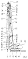
- a mobile drill shown in Figures 1 and 2 has a total of 10 chain running gear (Excavator). At the front left in the drawing The end of the undercarriage 10 is vertical via a joint 12 standing on the drawing level, in a horizontal An articulated frame 14 lies on the articulated axis articulated.
- the positioning frame 14 has essentially the shape of a isosceles triangle.
- the front is in detail Triangle side about 1.4 times as long as the base side, the back triangle side about 1.2 times as long as that Base side.
- actuating cylinder 16 At the upper corner of the frame 14 is the piston rod an actuating cylinder 16 attached via a joint 18.
- the cylinder housing of the actuating cylinder 16 is via another joint 20 on the top of the superstructure of the chassis 10 articulated.
- a first working slide 26 is vertical on this movable, the one designated a total of 28 Drill pipe drive carries. This works via a drive piece 30 on a drill pipe string 32.
- An upper work slide 34 has one drawn schematically at 36 Drill drive, which has a drive piece 38 on a Drill 40 works.
- a leader head carried by the top of leader 24 42 contains various sheaves, over which ropes S1 and S2 for lifting and lowering the two work slides 26, 34 and other ropes e.g. a rope S3 of a hoist run.
- ropes S1 and S2 For moving the ropes S1 and S2 serve winches W1 and W2 in the chassis 10 to move the Rope S3 has a winch W3 on the back of the leader 24 is attached in the lower area.
- the leader 24 consists of a lower leader segment 44 and an upper leader segment 46 of the same cross section, that butt against each other in the leader's working position, so that even in the joint area smooth Has outer surfaces of the leader.
- the two leader segments 44, 46 are connected via a further joint 48, the behind the chassis-side, rear boundary surface of leader 24 is.
- End sections of the two leader segments 44, 46 are one end sections via further joints 50, 52 two links 54, 56 attached, the second ends are connected by an articulated rod 58.
- the articulation points of the two links 54, 56 on the leader segments 44, 46 are equidistant from the abutting surface the leader segments removed.
- the lower link 54 is slightly longer than the upper link 56 (its length is about 1.2 times the length of the upper handlebar), so that the hinge rod 58 is slightly above the hinge 48 lies.
- the lengths of the links 54, 56 are also so dimensioned that the pivot pin 58 in the working position of leader 24 is somewhat in front of joint 20.
- the lower link 54 carries in the vicinity of its rear End of a pulley 59 over which the rope S3 runs. In this way it stays between the winch W3 and the lower handlebar 54 free space for further add-on components.
- the piston rods are also two lower support cylinder 60 articulated, the front or behind the longitudinal median plane of the superstructure of the Chain trolley 10 lie and upwards on the longitudinal center plane of running gear 10 to run.
- the cylinder housing of the two support cylinders 60 are at the bottom End hinged to the pivot pin 18 on which also attacks the piston rod of the actuating cylinder 16.
- hinge rod 58 On the hinge rod 58 is also the lower end of the Cylinder housing of an upper support cylinder 62 attached, whose piston rod via another joint 64 is connected to the upper leader segment 46.
- the actuating cylinder 14 is extended, the upper support cylinder 62 retracted and the lower Support cylinder 60 also retracted, and here fold the leader segments 44, 46 such that the lower leader segment rising at a small angle lies in front of the chassis 10 and the upper leader segment 46 lies horizontally above the top of the chassis 10.
- the leader head 42 is after loosening one of two pin connections, over it with the top of the leader connected, folded down so that it is not in protrudes in the vertical direction above the lying leader.
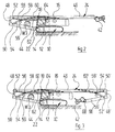
- a leader 24 in three segments divided, namely the lower leader segment 44, a middle leader segment 46 and an upper leader segment 66.
- the connection between the lower leader segment 44 and middle leader segment 46 is made as described above.
- the connection between the top Leader segment 66 and the middle leader segment 64 is a mirror image of the connection between the lower one and middle leader segment.
- the connections between leader segments therefore do not need to be described again in detail.
- the leader's head 42 is by an intermediate piece 68 in one of the positions of Figure 2 but now corresponding raised position held.
Landscapes
- Engineering & Computer Science (AREA)
- Life Sciences & Earth Sciences (AREA)
- Mining & Mineral Resources (AREA)
- General Life Sciences & Earth Sciences (AREA)
- Geology (AREA)
- Physics & Mathematics (AREA)
- General Engineering & Computer Science (AREA)
- Structural Engineering (AREA)
- Civil Engineering (AREA)
- Environmental & Geological Engineering (AREA)
- Fluid Mechanics (AREA)
- Paleontology (AREA)
- Geochemistry & Mineralogy (AREA)
- Electrical Discharge Machining, Electrochemical Machining, And Combined Machining (AREA)
- Harvester Elements (AREA)
- Transplanting Machines (AREA)
- Earth Drilling (AREA)
Abstract
Description
Die Erfindung betrifft ein fahrbares Arbeitsgerät gemäß
dem Oberbegriff des Anspruches 1.The invention relates to a mobile implement according to
the preamble of
Ein derartiges Arbeitsgerät, welches ein Bohrgerät ist
in der DE 36 10 814 C2 beschrieben. Bei ihm ist ein
unteres Segement des Mäklers in einer horizontalen Ruhestellung
des Mäklers nach unten abgeklappt, um einen
auf diesem Mäklersegment zum Transport geparkten Bohrrohrantrieb
soweit abzusenken, daß dieser nicht über
die in der Ruheposition obere Begrenzungsfläche des
Mäklers übersteht.Such an implement, which is a drilling device
described in
Auch bei einem derartigen Arbeitsgerät steht der in Ruhestellung gelegte Mäkler nach vorn und hinten noch weit über das den Mäkler tragende Fahrwerk über, was bei sehr langen Mäklern den Transport über öffentliche Straßen erschwert, wenn Kurven durchfahren werden müssen.Even with such a tool is in Leader in the rest position to the front and back far beyond the chassis carrying the leader about what in the case of very long leaders, transportation by public Roads difficult when curves have to be negotiated.
Durch die vorliegende Erfindung soll ein Arbeitsgerät
gemäß dem Oberbegriff des Anspruches 1 so weitergebildet
werden, daß in der Ruheposition des Mäklers dessen Enden
weniger weit über das Fahrwerk nach vorn bzw. hinten
überstehen.The present invention is intended to be an implement
further developed according to the preamble of
Diese Aufgabe ist erfindungsgemäß gelöst durch ein Arbeitsgerät
mit den im Anspruch 1 angegebenen Merkmalen.This object is achieved by an implement
with the features specified in
Bei dem erfindungsgemäßen Arbeitsgerät ist der Mäkler in der Ruheposition gefaltet, so daß der vor dem Fahrwerk liegende Raum übereinanderliegend zwei Mäklerabschnitte enthält, deren Achsen einen spitzen Winkel einschließen. Durch ein solches Zusammenfalten des Mäklers wird der vom Mäkler in der Ruhestellung benötigte Raum deutlich vermindert, in der Praxis größenordnungsmäßig um 25%.In the implement according to the invention is the leader folded in the rest position so that the front of the chassis space lying on top of each other two leader sections contains whose axes are at an acute angle lock in. By folding the leader like this is the one required by the leader in the rest position Space significantly reduced, in practice of the order of magnitude by 25%.
Ein Vorteil bei der erfindungsgemäßen Lösung ist auch, daß man durch die beiden in der Arbeitsstellung des Mäklers mechanisch in Reihe geschalteten längenverstellbaren Streben eine Abstützung des Mäklers an einem verhältnismäßig hoch gelegenen Punkt unter Verwendung von axial nur kurzen längenverstellbaren Streben erhält. Bei vorgegebener Knickfestigkeit können somit die längenverstellbaren Streben schwächer dimensioniert werden, was insbesondere bei Verwendung von hydraulischen Streben (Stützzylindern) erhebliche Kosteneinsparungen ermöglicht.Another advantage of the solution according to the invention is that that by the two in the working position of the Mäklers mechanically adjustable in length Strive for the leader to be supported proportionately high point using receives axially only short length-adjustable struts. With a given kink resistance, the length-adjustable ones can be adjusted Struts are dimensioned weaker, what especially when using hydraulic struts (Support cylinders) enables considerable cost savings.
Vorteilhafte Weiterbildungen der Erfindung sind in Unteransprüchen der Erfindung angegeben.Advantageous developments of the invention are in the subclaims specified the invention.
Die Weiterbildung der Erfindung gemäß Anspruch 2 macht
es möglich, daß die beiden Mäklersegmente in der Arbeitsstellung
des Mäklers eine im wesentlichen glatt durchgehende
stoßfreie Struktur bilden, so daß vom Mäkler getragene
Schlitten problemlos über die Stoßstelle bewegt
werden können und eine gute Kraftübertragung sowie eine
gute Kippmomentübertragung zwischen den beiden Mäklersegmenten
gewährleistet ist.The development of the invention according to
Die Weiterbildung der Erfindung gemäß Anspruch 3 schafft
zum einen auf der Hinterseite des unteren Mäklersegmentes
freien Raum, in welchen Winden oder andere schwerere und
Platz benötigende Zusatzkomponenten des Arbeitsgerätes
angebaut werden können. Zudem erhält man durch die gemäß
Anspruch 3 vorgesehenen Lenker auch günstige Hebelverhältnisse
für das Angreifen der unteren längenverstellbaren
Strebe bzw. das Abstützen der oberen längenverstellbaren
Strebe.The development of the invention according to
Mit der Weiterbildung der Erfindung gemäß Anspruch 4 wird erreicht, daß der Mäkler in seiner Ruheposition keine größeren Kippmomente auf das Fahrwerk ausübt.With the development of the invention according to claim 4 is achieved that the leader in its rest position does not exert any major tilting moments on the chassis.
Mit der Weiterbildung der Erfindung gemäß Anspruch 5 wird erreicht, daß der Mäkler in seiner Ruheposition über das Fahrwerk nach vorn und nach hinten im wesentlichen gleich weit übersteht.With the development of the invention according to claim 5 is achieved that the leader in its rest position essentially about the chassis forward and backward survives equally far.
Die Weiterbildung der Erfindung gemäß Anspruch 6 ist im Hinblick auf eine symmetrische Kraftübertragung zwischen den gegeneinander verschwenkbaren Mäklersegmenten und der Strebenanordnung von Vorteil.The development of the invention is according to claim 6 in terms of symmetrical power transmission between the leader segments that can be pivoted towards each other and the strut arrangement is advantageous.
Die Weiterbildung der Erfindung gemäß Anspruch 7 ist im Hinblick auf günstige Hebelverhältnisse beim Zusammenfalten und Auseinanderfalten des Mäklers von Vorteil und kompensiert eine Asymmetrie des gefalteten Mäklers, die darin besteht, daß das untere Mäklersegment in der Ruheposition leicht nach oben ansteigt, da das obere Mäklersegment parallel über dem Fahrwerk verlaufen muß.The development of the invention is according to claim 7 in terms of favorable leverage when folding and unfolding the leader is an advantage and compensates for an asymmetry of the folded leader, which is that the lower leader segment in the Rest position rises slightly as the upper one Leader segment must run parallel above the chassis.
Die Weiterbildung der Erfindung gemäß Anspruch 9 ermöglicht das Vorsehen einer Seilwinde auf dem unteren Mäklerabschnitt derart, daß neben ihr noch freier Raum für weiter einzubauende Komponenten auf dem unteren Mäklerabschnitt verbleibt.The development of the invention according to claim 9 enables the provision of a winch on the lower leader section in such a way that there is still room for Components to be installed on the lower leader section remains.
Die Weiterbildung der Erfindung gemäß Anspruch 10 ermöglicht
es, den Abstand zwischen der Mäklerachse und dem
vorderen Ende Fahrwerkes einzustellen. The development of the invention according to
Dabei ist die Weiterbildung der Erfindung gemäß Anspruch 11 deshalb besonders vorteilhaft, weil man die erste längenverstellbare Strebe axial kürzer wählen kann.The development of the invention is according to claim 11 particularly advantageous because you are the first adjustable strut axially shorter.
Die Weiterbildungen der Erfindung gemäß den Ansprüchen
12 und 13 sind im Hinblick auf eine günstige Mäkler-Verstellgeometrie
von Vorteil.The developments of the invention according to the
Mit der Weiterbildung der Erfindung gemäß Anspruch 13 wird erreicht, daß die dritte längenverstellbare Strebe in der Arbeitsstellung des Mäklers nicht stark belastet ist.With the development of the invention according to claim 13 is achieved that the third adjustable strut not heavily loaded in the leader's working position is.
Die Weiterbildung der Erfindung gemäß Anspruch 14 ist
im Hinblick auf einfache Herstellung und kompakten Aufbau
der Mäkler-Verstellmechanik vor Vorteil.The development of the invention according to
Die Anordnung von ersten längenverstellbaren Streben (Anspruch 15) zu beiden Seiten der Längsmittelebene des Fahrwerkes ist im Hinblick auf eine gute Aufnahme von seitlichen Kippmomenten von Vorteil.The arrangement of the first adjustable struts (Claim 15) on both sides of the longitudinal median plane of the Landing gear is in view of a good absorption of lateral tilting moments are an advantage.
Die Weiterbildung der Erfindung gemäß Anspruch 16 erlaubt
eine weitere Reduzierung der Länge des Mäklers in seiner
Ruheposition.The development of the invention according to
Bei einem Arbeitsgerät gemäß Anspruch 17 kann man eine sichere Verriegelung der längenverstellbaren Streben in den jeweils eingestellten Positionen erhalten, ohne daß mechanische Verriegelungen hergestellt oder gelöst werden müßten. Dies ist im Hinblick auf ein rasches Umstellen des Mäklers zwischen Ruhestellung und Arbeitsstellung und auch deshalb von Vorteil, weil die Stellen, wo die mechanischen Verriegelungen vorgesehen werden müßten, schlecht zugänglich sind.In a working device according to claim 17, one can secure locking of the length-adjustable struts received in the positions set, without that mechanical locks made or released should be. This is in view of a quick Switching the leader between rest position and working position and also advantageous because the places where the mechanical interlocks are provided should be difficult to access.
Nachstehend wird die Erfindung anhand von Ausführungsbeispielen unter Bezugnahme auf die Zeichnung näher erläutert. In dieser zeigen:
- Figur 1:
- eine seitliche Ansicht eines Bohrgerätes in der Arbeitsstellung;
- Figur 2:
- eine seitliche Ansicht des in
Figur 1 gezeigten Bohrgerätes in seiner Transportstellung; und - Figur 3:
- eine ähnliche Ansicht wie
Figur 2, in welcher jedoch ein abgewandeltes Bohrgerät wiedergegeben ist.
- Figure 1:
- a side view of a drill in the working position;
- Figure 2:
- a side view of the drill shown in Figure 1 in its transport position; and
- Figure 3:
- a view similar to Figure 2, but in which a modified drill is shown.
Ein in den Figuren 1 und 2 gezeigtes fahrbares Bohrgerät
hat ein insgesamt mit 10 bezeichnetes Kettenfahrwerk
(Bagger). Am in der Zeichnung links gelegenen, vorderen
Ende des Fahrwerkes 10 ist über ein Gelenk 12 mit senkrecht
auf der Zeichenebene stehender, in einer horizontalen
Ebene liegender Gelenkachse ein Stellrahmen 14
angelenkt.A mobile drill shown in Figures 1 and 2
has a total of 10 chain running gear
(Excavator). At the front left in the drawing
The end of the
Der Stellrahmen 14 hat im wesentlichen die Form eines
gleichschenkligen Dreieckes. Im einzelnen ist die vordere
Dreiecksseite etwa 1,4 mal so lang wie die Basisseite,
die hintere Dreiecksseite etwa 1,2 mal so lang wie die
Basisseite.The
Am oberen Eckpunkt des Stellrahmens 14 ist die Kolbenstange
eines Stellzylinders 16 über ein Gelenk 18 angebracht.
Das Zylindergehäuse des Stellzylinders 16 ist
über ein weiteres Gelenk 20 an der Oberseite des Oberwagens
des Fahrwerkes 10 angelenkt. At the upper corner of the
Beim in Figur 1 links gelegenen vorderen Ende des Stellrahmens 14 ist über ein weiteres Gelenk 22 das untere Ende eines insgesamt mit 24 bezeichneten Mäklers eingelenkt.At the front end of the positioning frame on the left in FIG. 1 14 is the lower via a further joint 22 End of a leader marked with a total of 24.
Auf diesem ist ein erster Arbeitsschlitten 26 vertikal
verfahrbar, der einen insgesamt mit 28 bezeichneten
Bohrrohrantrieb trägt. Dieser arbeitet über ein Antriebsstück
30 auf einen Bohrrohrstrang 32. Ein oberer Arbeitsschlitten
34 hat einen schematisch bei 36 gezeichneten
Bohrerantrieb, der über ein Antriebsstück 38 auf einen
Bohrer 40 arbeitet.A first working slide 26 is vertical on this
movable, the one designated a total of 28
Drill pipe drive carries. This works via a
Ein vom oberen Ende des Mäklers 24 getragener Mäklerkopf
42 enthält verschiedene Seilscheiben, über welche Seile
S1 und S2 zum Anheben und Absenken der beiden Arbeitsschlitten
26, 34 sowie weitere Seile z.B. ein Seil S3
eines Hebezeuges laufen. Zum Bewegen der Seile S1 und S2
dienen Winden W1 und W2 im Fahrwerk 10, zum Bewegen des
Seiles S3 eine Winde W3, die auf der Rückseite des Mäklers
24 im unteren Bereich angebracht ist.A leader head carried by the top of
Der Mäkler 24 besteht aus einem unteren Mäklersegment
44 und einem oberen Mäklersegment 46 gleichen Querschnittes,
die in der Arbeitsstellung des Mäklers stumpf aneinanderstoßen,
so daß man auch im Stoßbereich glatt durchgehende
Außenflächen des Mäklers hat. Die beiden Mäklersegmente
44, 46 sind über ein weiteres Gelenk 48 verbunden, das
hinter der fahrwerksseitigen, hinteren Begrenzungsfläche
des Mäklers 24 liegt.The
In den dem Gelenk 48 benachbarten einander gegenüberliegenden
Endabschnitten der beiden Mäklersegmente 44,
46 sind über weitere Gelenke 50, 52 die einen Endabschnitte
zweier Lenker 54, 56 angebracht, deren zweite Enden
durch einen Gelenkstab 58 verbunden sind.In the opposite to each other adjacent the
Die Anlenkpunkte der beiden Lenker 54, 56 auf den Mäklersegementen
44, 46 sind gleich weit von der Stoßfläche
der Mäklersegmente entfernt. Der untere Lenker 54 ist
etwas länger als der obere Lenker 56 (seine Länge beträgt
etwa das 1,2-fache der Länge des oberen Lenkers),
so daß der Gelenkstab 58 etwas oberhalb des Gelenkes
48 liegt. Die Längen der Lenker 54, 56 sind ferner so
bemessen, daß der Gelenkzapfen 58 in der Arbeitsstellung
des Mäklers 24 etwas vor dem Gelenk 20 liegt.The articulation points of the two
Der untere Lenker 54 trägt in der Nachbarschaft seines hinteren
Endes eine Seilscheibe 59, über die das Seil S3 läuft.
Auf diese Weise bleibt der zwischen der Winde W3 und dem
unteren Lenker 54 liegende Raum frei für weitere Anbaukomponenten.The
Am Gelenkstab 58 sind ferner die Kolbenstangen zweier
unterer Stützzylinder 60 gelenkig angebracht, die vor
bzw. hinter der Längsmittelebene des Oberwagens des
Kettenfahrwerkes 10 liegen und nach oben auf die Längsmitteleebene
des Fahrwerkes 10 zu verlaufen. Die Zylindergehäuse
der beiden Stützzylinder 60 sind am unteren
Ende gelenkig mit dem Gelenkzapfen 18 verbunden, an welchem
auch die Kolbenstange des Stellzylinders 16 angreift.On the
Auf dem Gelenkstab 58 ist ferner das untere Ende des
Zylindergehäuses eines oberen Stützzylinders 62 angebracht,
dessen Kolbenstange über ein weiteres Gelenk
64 mit dem oberen Mäklersegment 46 verbunden ist.On the
Wie aus der Zeichnung ersichtlich, bilden die rechte
Seite des Stellrahmens 14, der untere Stützzylinder
60 und der obere Stützzylinder 62 in der Arbeitsstellung
des Mäklers eine Strebe mit um kleine Winkel gegeneinander
verkippten Strebenabschnitten, welche den Mäkler
24 abstützt.As can be seen from the drawing, form the right one
Side of the
Durch Ausfahren des Stellzylinders 16 kann man den Stellrahmen
14 im Uhrzeigersinne verschwenken, wodurch der
Abstand zwischen dem Gelenk 22 und der Vorderseite des
Fahrwerkes 10 und die vertikale Stellung des unteren
Endes des Mäklers 24 eingestellt werden können.By extending the
Durch Änderung der Länge des unteren Stützzylinders
60 läßt sich die Neigung des Mäklers 24 einstellen. Der
obere Stützzylinder 62 wird in der Arbeitsstellung des
Mäklers immer voll ausgefahren gehalten, wodurch die
Mäklersegmente 44, 46 in fluchtender Lage gehalten werden.By changing the length of the
Zum Überführen des Mäklers 24 in die in Figur 2 gezeigte
Transportstellung wird der Stellzylinder 14 ausgefahren,
der obere Stützzylinder 62 eingefahren und der untere
Stützzylinder 60 ebenfalls eingefahren, und hierbei
falten sich die Mäklersegemente 44, 46 derart, daß das
untere Mäklersegment unter kleinem Winkel ansteigend
vor dem Fahrwerk 10 liegt und das obere Mäklersegment
46 horizontal über der Oberseite des Fahrwerkes 10 liegt.
Der Mäklerkopf 42 ist nach Lösen einer von zwei Absteckverbindungen,
über die er mit dem oberen Ende des Mäklers
verbunden ist, nach unten abgeklappt, sodaß er nicht in
vertikaler Richtung über den liegenden Mäkler übersteht.For transferring
Bei den gegebenen Längenverhältnissen zwischen unterem Mäklersegment und oberem Mäklersegment steht der Mäkler in der Ruhe- oder Transportposition in etwa gleich weit nach vorn und hinten über das Fahrwerk über. Given the length ratios between the lower Leader segment and upper leader segment is the leader roughly the same distance in the resting or transport position forwards and backwards over the chassis.
Bei dem in Figur 3 gezeigten weiter abgewandelten Ausführungsbeispiel
ist ein Mäkler 24 in drei Segmente
unterteilt, nämlich das untere Mäklersegment 44, ein
mittleres Mäklersegment 46 und ein oberes Mäklersegment
66. Die Verbindung zwischen unterem Mäklersegment 44
und mittlerem Mäklersegment 46 ist so vorgenommen, wie
oben beschrieben. Die Verbindung zwischen dem oberen
Mäklersegment 66 und dem mittleren Mäklersegment 64
ist spiegelbildlich zur Verbindung zwischen unterem
und mittlerem Mäklersegment ausgebildet. Die Verbindungen
zwischen den Mäklersegmenten brauchen somit nicht
nochmals detailliert beschrieben zu werden. Der Mäklerkopf
42 wird durch ein Zwischenstück 68 in einer der Stellung
von Figur 2 entsprechenden nun aber angehobenen Stellung
gehalten.In the further modified embodiment shown in FIG. 3
is a
Bei den oben beschriebenen Ausführungsbeispielen sind für das Zusammenfalten und Auseinanderfalten sowie das Verriegeln der Mäklersegmente in der Arbeitsstellung und der Transportstellung des Mäklers Stützzylinder vorgesehen. Es versteht sich daß man hierzu auch andere Antriebe (z.B. Seiltriebe) und andere Verriegelungsmittel (z.B. Absteck-Verbindungen) verwenden kann.In the embodiments described above are for folding and unfolding and locking the leader segments in the working position and the transport position the leader's support cylinder. It understands that other drives (e.g. rope drives) and other locking devices (e.g. pinning connections) can use.
Claims (17)
Applications Claiming Priority (2)
| Application Number | Priority Date | Filing Date | Title |
|---|---|---|---|
| DE29718149U DE29718149U1 (en) | 1997-10-10 | 1997-10-10 | Mobile working device |
| DE29718149U | 1997-10-10 |
Publications (1)
| Publication Number | Publication Date |
|---|---|
| EP1010816A1 true EP1010816A1 (en) | 2000-06-21 |
Family
ID=8047165
Family Applications (1)
| Application Number | Title | Priority Date | Filing Date |
|---|---|---|---|
| EP98116371A Withdrawn EP1010816A1 (en) | 1997-10-10 | 1998-08-28 | Mobile work apparatus |
Country Status (2)
| Country | Link |
|---|---|
| EP (1) | EP1010816A1 (en) |
| DE (1) | DE29718149U1 (en) |
Cited By (1)
| Publication number | Priority date | Publication date | Assignee | Title |
|---|---|---|---|---|
| EP1752608A2 (en) * | 2005-08-11 | 2007-02-14 | National-Oilwell, L.P. | Portable drilling mast structure, rig and method for erecting |
Families Citing this family (2)
| Publication number | Priority date | Publication date | Assignee | Title |
|---|---|---|---|---|
| DE202008007970U1 (en) | 2008-06-13 | 2008-09-04 | Bauer Maschinen Gmbh | Construction work tool with swiveling mast |
| DE102009025084A1 (en) * | 2009-06-16 | 2010-12-23 | Liebherr-Werk Nenzing Gmbh, Nenzing | Piling and drilling device with hinged deflection device |
Citations (5)
| Publication number | Priority date | Publication date | Assignee | Title |
|---|---|---|---|---|
| US4371046A (en) * | 1980-04-21 | 1983-02-01 | Vernon Read | Apparatus for and method of drilling a hole into the ground |
| DE4436264C1 (en) * | 1994-10-11 | 1995-11-30 | Wirth Co Kg Masch Bohr | Drilling mast hinged to body and erected by power cylinders |
| US5558169A (en) * | 1995-02-13 | 1996-09-24 | Kenneth B. Madgwick | Truck mounted work implement |
| EP0745528A2 (en) * | 1995-06-01 | 1996-12-04 | Klaus Obermann GmbH | Universal construction apparatus |
| DE3610814C2 (en) | 1986-04-01 | 1997-07-24 | Delmag Maschinenfabrik | Mobile drilling, ramming or similar device |
-
1997
- 1997-10-10 DE DE29718149U patent/DE29718149U1/en not_active Expired - Lifetime
-
1998
- 1998-08-28 EP EP98116371A patent/EP1010816A1/en not_active Withdrawn
Patent Citations (5)
| Publication number | Priority date | Publication date | Assignee | Title |
|---|---|---|---|---|
| US4371046A (en) * | 1980-04-21 | 1983-02-01 | Vernon Read | Apparatus for and method of drilling a hole into the ground |
| DE3610814C2 (en) | 1986-04-01 | 1997-07-24 | Delmag Maschinenfabrik | Mobile drilling, ramming or similar device |
| DE4436264C1 (en) * | 1994-10-11 | 1995-11-30 | Wirth Co Kg Masch Bohr | Drilling mast hinged to body and erected by power cylinders |
| US5558169A (en) * | 1995-02-13 | 1996-09-24 | Kenneth B. Madgwick | Truck mounted work implement |
| EP0745528A2 (en) * | 1995-06-01 | 1996-12-04 | Klaus Obermann GmbH | Universal construction apparatus |
Cited By (2)
| Publication number | Priority date | Publication date | Assignee | Title |
|---|---|---|---|---|
| EP1752608A2 (en) * | 2005-08-11 | 2007-02-14 | National-Oilwell, L.P. | Portable drilling mast structure, rig and method for erecting |
| EP1752608A3 (en) * | 2005-08-11 | 2007-10-03 | National-Oilwell, L.P. | Portable drilling mast structure, rig and method for erecting |
Also Published As
| Publication number | Publication date |
|---|---|
| DE29718149U1 (en) | 1998-01-08 |
Similar Documents
| Publication | Publication Date | Title |
|---|---|---|
| DE69200225T2 (en) | Automatically foldable crane boom. | |
| EP0056118A1 (en) | Foldable apparatus or frame for agricultural machines | |
| DE2658250A1 (en) | MOBILE AND LIFTING BASKET | |
| DE102017101113B3 (en) | Telescopic boom with pole tensioning system for a mobile crane and guying method | |
| DE3824732A1 (en) | CRANE, IN PARTICULAR LARGE CRANE | |
| DE3517853A1 (en) | EXTENDABLE DEVICE | |
| DE102018115519B3 (en) | Mobile crane with a movable adapter between main boom and main boom extension | |
| DE1481873A1 (en) | Load lifting device | |
| DE2822110A1 (en) | USE CRANE | |
| AT395992B (en) | TRACKED VEHICLE, IN PARTICULAR HYDRAULIC EXCAVATORS | |
| DE20002748U1 (en) | Mobile crane | |
| EP0590123B1 (en) | Variable gauge running gear | |
| EP1077306B1 (en) | Mobile work apparatus | |
| DE2843587C2 (en) | Lifting device with a platform for a boom that can be rotated about a vertical axis | |
| DE60007488T2 (en) | Collapsing device of a crane jib with intermeshable elements | |
| EP0356761A1 (en) | Scissor lift device, especially for a working platform | |
| DE2138674C3 (en) | Side loading device of a container vehicle | |
| DE1634733C3 (en) | Shovel excavator | |
| EP3898492A1 (en) | Assembly with a boom that can be luffed by two luffing cylinders, and correspondingly equipped vehicle crane | |
| DE1630973A1 (en) | Mobile jib crane | |
| EP1010816A1 (en) | Mobile work apparatus | |
| DE69810981T2 (en) | Technique for erecting the mast for a telescopic crane | |
| DE20107984U1 (en) | Mobile crane with luffing jib | |
| DE2450003C2 (en) | Mobile crane with cabin with different positions | |
| DE19745625A1 (en) | Self propelled tracked drill |
Legal Events
| Date | Code | Title | Description |
|---|---|---|---|
| PUAI | Public reference made under article 153(3) epc to a published international application that has entered the european phase |
Free format text: ORIGINAL CODE: 0009012 |
|
| AK | Designated contracting states |
Kind code of ref document: A1 Designated state(s): AT BE CH DE DK ES FI FR GB GR IT LI LU NL PT SE |
|
| AX | Request for extension of the european patent |
Free format text: AL;LT;LV;MK;RO;SI |
|
| 17P | Request for examination filed |
Effective date: 20001110 |
|
| AKX | Designation fees paid |
Free format text: AT BE CH DE DK ES FI FR GB GR IT LI LU NL PT SE |
|
| AXX | Extension fees paid |
Free format text: LT PAYMENT 20001110;LV PAYMENT 20001110;SI PAYMENT 20001110 |
|
| STAA | Information on the status of an ep patent application or granted ep patent |
Free format text: STATUS: THE APPLICATION IS DEEMED TO BE WITHDRAWN |
|
| 18D | Application deemed to be withdrawn |
Effective date: 20030301 |