EP0224166B1 - Spraying boom for a field sprayer - Google Patents
Spraying boom for a field sprayer Download PDFInfo
- Publication number
- EP0224166B1 EP0224166B1 EP86115921A EP86115921A EP0224166B1 EP 0224166 B1 EP0224166 B1 EP 0224166B1 EP 86115921 A EP86115921 A EP 86115921A EP 86115921 A EP86115921 A EP 86115921A EP 0224166 B1 EP0224166 B1 EP 0224166B1
- Authority
- EP
- European Patent Office
- Prior art keywords
- cable
- field sprayer
- sections
- spray boom
- sprayer according
- Prior art date
- Legal status (The legal status is an assumption and is not a legal conclusion. Google has not performed a legal analysis and makes no representation as to the accuracy of the status listed.)
- Expired - Lifetime
Links
Images
Classifications
-
- A—HUMAN NECESSITIES
- A01—AGRICULTURE; FORESTRY; ANIMAL HUSBANDRY; HUNTING; TRAPPING; FISHING
- A01M—CATCHING, TRAPPING OR SCARING OF ANIMALS; APPARATUS FOR THE DESTRUCTION OF NOXIOUS ANIMALS OR NOXIOUS PLANTS
- A01M7/00—Special adaptations or arrangements of liquid-spraying apparatus for purposes covered by this subclass
- A01M7/005—Special arrangements or adaptations of the spraying or distributing parts, e.g. adaptations or mounting of the spray booms, mounting of the nozzles, protection shields
- A01M7/0071—Construction of the spray booms
- A01M7/0075—Construction of the spray booms including folding means
Definitions
- the invention relates to an agricultural field sprayer with a spray boom according to the preamble of claim 1.
- Such an agricultural field sprayer is already known, for example, from German patent DE-C-31 19 093.
- the sprayer boom of this agricultural sprayer is divided into several sections on each boom side, which are connected to each other by means of joints that run upright in their swivel axes and can be brought into an extended and a folded position, the individual parts being moved from their working position into a remote control device their transport position and vice versa can be brought.
- the individual parts of the sprayer boom are in a zigzag position relative to one another. As soon as the sprayer boom is folded in or is to be folded out, all sections are moved simultaneously via the remote control device.
- the spray boom is divided into at least three sections on each side of the field sprayer, so that the working width of the spray boom can and should be reduced in the smallest possible sections of the spray boom.
- German utility model DE-U-18 59 848 discloses a sprayer boom, which each consists of two sections which can be folded together and which are connected to one another by means of a joint. This spray boom can be brought into a folded and extended position via a cable control.
- this known cable control is not suitable for folding a sprayer boom with more than two sections to each other.
- the invention has for its object to provide the simplest possible device for folding a sprayer boom, it should be possible in a simple manner that the sprayer boom in sections from the outside inwards by the remote control device, the further adjoining sections in their extended The next position should remain, should be retractable.
- the remote control device it is possible in the simplest way to design the remote control device so that the individual sections of the sprayer booms fold in one behind the other from the outside inward, with the sections located further inside initially remaining in their stretched position, without great design effort. Furthermore, when unfolding, the inner section is first unfolded, while the adjoining sections initially remain in their folded position and are then successively folded into their working position. It is provided according to the invention that the cable of the cable control is only attached to the outermost section of the sprayer boom and to a cable pull element arranged on the frame of the field sprayer, resulting in an extremely simple cable guide, which enables the individual sections in a surprisingly and incredibly simple manner expand or collapse one after the other.
- cable guide elements are arranged between the individual sections in the area of the respective joints, which keep the cable at a distance from the pivot axis of the joints.
- the joint axes of the inner joints, with which the innermost sections of the spray boom are articulated on the frame of the field sprayer each run approximately in the direction of travel.
- This compactly folded package can then be folded up around the innermost joint, the pivot axis of which runs in the direction of travel, and brought into an upright position behind the sprayer tank.In this transport position, the sprayer tank is very convenient from the side and without disturbing any rod parts directly accessible. Furthermore, the folded packages can be brought into a horizontal position, in which the spray lines and the nozzles, which are accommodated in the spray boom, can be easily cleaned without the spray boom having to be brought into its extended position. This is of great advantage especially for spray booms for large working widths, which are divided into many small sections. Furthermore, the folded and folded up spray boom is located behind the tank of the field sprayer in a protected area. This means that the spray boom in the transport position cannot be damaged during transport because it does not protrude laterally from the syringe.
- the innermost part of the sprayer boom above the joint running approximately in the direction of travel has an arm projecting above the joint and that the folding rope above this arm is led.
- the folding ropes and the folding ropes are each effective in opposite directions to one another. This makes it possible to create an extremely simple actuating device for the cable control.
- the folding ropes and the folding ropes for the two spray boom sides are each connected to one another. As a result, it is very easily possible to use an actuating device for folding in or out both sides. It is therefore possible that both sides can be folded in at the same time.
- individual sections are rigidly locked to one another or the folding or unfolding rope is held or clamped for one side of the sprayer boom, so that only one side is then folded in or out or in sections and in and out is unfolded.
- the invention provides that the fold-out moments can be built up from the inside to the outside while the fold-in moments can be built up from the outside in.
- a counterforce against the force of the Folding rope can be applied, and that a counterforce against the force of the folding rope can be applied when unfolding by the folding rope.
- the ropes are each arranged in block-and-tackle fashion between the inner section of the sprayer boom, while the ropes are deflected between the outer sections essentially via different lever arms.
- the pulley-like deflection of the ropes between the inner sections results in an extremely compact construction of the rope guide.
- a tension spring is arranged in the folding rope in the region of the outer sections.
- the field sprayer has the tank 1 shown with broken lines with a filling opening and a frame, not shown.
- the support frame 2 of the sprayer boom 3 is adjustable in the height direction on the frame of the field sprayer and is arranged in an oscillating manner in a known and therefore not shown manner.
- the spray boom 3 is divided into several sections which are connected to one another by means of the joints 4, 5, 6 and 7.
- the innermost section 8 of the spray boom 3 is arranged on the support frame 2 with the joint 4, the pivot axis of which extends approximately in the direction of travel of the field sprayer.
- the sections 9, 10 and 11 of the spray boom 3 adjoining the innermost section 8 can each be pivoted about upright axes.
- the spray boom 3 shown in FIGS. 1 and 2 is in its extended position, which corresponds to the working position.
- the sprayer boom 3 is in a folded position, via the position shown in FIG. 3 into that shown in FIG. 4 folded to bring position that corresponds to the transport position. This is done via a remote control device designed as a cable control.
- the remote control device designed as a cable control 12 has the folding rope 13 and the folding rope 14.
- the folding rope 13 and the folding rope 14 are each fixed at a distance from the joint 7 to the outermost section 11 of the sprayer boom 3.
- the folding rope 13 and the folding rope 14 are attached to the support frame 2.
- the respective folding rope 13 or the respective folding rope 14 of the two sides of the sprayer boom 3 can be connected to one another.
- the operating devices of the cable control 12, which are designed as folding cylinders 15 and folding cylinders 16, are arranged on the support frame 2.
- the folding cylinder 15 and the folding cylinder 16 are designed as single-acting hydraulic cylinders.
- Rope guiding elements are arranged between the individual gates 8, 9, 10 and 11 of the sprayer boom 3, which hold the ropes 13 and 14 at a distance from the pivot axis of the respective joints 4, 5, 6 and 7.
- the arm 17 projecting upwards above the joint 4 is arranged above the joint 4.
- This arm 17 has at its upper end the rope guide element designed as a rope pulley 18.
- This pulley 18 is freely rotatably mounted on the arm 17.
- the two small rope pulleys 20 for deflecting the fold-out rope 16 are arranged on the sections 8 and 9 of the spray boom 3 in the region of the joint 5. These pulleys 20 are also freely rotatable arranged. Between the sections 9 and 10, the two rope guide elements designed as rope pulleys 21 are freely rotatable on the hinge pin of the hinge 6. Between the individual sections 10 and 11, the rope guiding elements designed as rope pulleys 22 and 23 are freely rotatable on the hinge pin of the hinge 7.
- the folding rope 13 is attached to the outermost portion 11 of the sprayer boom 3.
- the folding rope 13 is then guided around the large rope pulley 23, which is mounted on the hinge pin of the hinge 7.
- the folding rope 13 is then guided around the small rope pulley 24, which is freely rotatable in the outer area of the section 10.
- the folding rope 13 is then guided around the small rope pulley 25, which is freely rotatably mounted in the inner region of the section 10 of the spray boom 3.
- the folding rope 13 is guided around the lower roller 21.
- the folding rope 13 is guided around by the rope pulley 26, which is freely rotatably mounted on the section 9 in the outer region.
- the folding rope 13 is guided around the roller 27, which is freely rotatably mounted on the inner region of the section 9, before it is passed around the roller 19 and the rope pulley 28, which is arranged on the inner region of the section 8 in a freely rotatable manner.
- the folding rope 13 is guided around the roller 29, which is arranged in the vicinity of the joint 4 and is freely rotatably supported, before the folding rope 13 is guided around the rope roller 18.
- the folding rope 13 is then deflected around the rope pulley 30 arranged on the support frame 2. After the rope pulley 30, the folding rope 13 is guided over the deflection roller 31 arranged on the folding cylinder 15 and fastened to the support frame 2.
- the fold-out rope 13 is at a distance from the joint 7 attached to the outer portion 11. While the linkage is being folded in, the pull-out cable 14 is placed around the small cable pulley 22. Before the fold-out cable 14 is mounted on the cable pulley 32, which is freely rotatable in the inner region of section 10, the tension spring 33 is arranged in the fold-out cable 14. Furthermore, the fold-out rope 14 is guided over the rope pulley 34 arranged in the outer region of the section 9. When the sprayer boom 3 is folded in, the fold-out rope 14 lies in the region of the joint 6 around the lower pulley 21, which is arranged on the hinge pin of the joint 6. Furthermore, the fold-out rope 14 is guided in the wrong way over the rope pulleys 35 and 36.
- the cable pulley 34 is arranged in the inner region of the section 9, while the cable pulley 35 is freely rotatably mounted in the outer region of the section 8.
- the folding rope 14 which is guided in a pulley-like manner over the rollers 34 and 35, lies around the upper three cable rollers 19, which are arranged on the articulation pin of the articulation 5.
- the folding rope 14 is guided around the rope pulley 37, which is freely rotatably mounted on the support frame 2.
- the fold-out cable 14 is guided around the cable pulley 38 rotatably mounted on the fold-out cylinder 16 and fastened at its end to the support frame 2.
- the folding rope 13 is located on the side of the respective joint 5, 6 and 7 to which the mutually adjacent sections 8, 9, 10 and 11 can be folded together, while the folding rope 14 is located on the other side of the joints 5, 6 , and 7 is located.
- the folding ropes 13 and the folding ropes 14 are each effective in opposite directions to one another. Due to the differently sized rollers 22, 23, 21 and the pulley-like cable deflection in the area of the joint 5, the fold-out moments can be built up from the inside out while the folding moments can be built up from the outside to the inside.
- the sprayer booms are folded in or out as follows:
- the folding cylinder 13 connected to the tractor hydraulic system is extended via a hydraulic operating lever. Extending the folding cylinder 13 shortens the folding rope in the area of the sprayer boom 3.
- the sections 11 are folded back 180 ° to the section 10 of the distributor linkage 3. If the section 11 is folded up to the respective section 10, the sections 10 and 11 are folded together forward by 108 ° to the section 9 of the sprayer boom 3. When the section 10 with the section 11 abuts the section 9 of the sprayer boom 3, the sections 9, 10 and 11 are folded back together around the joint 9 to the section 8 of the sprayer boom 3.
- section 9 now comes to rest on the section 8 of the spray boom 3, and so the sections 8, 9, 10 and 11 form a compact package, as shown in FIG. 3, will this package of sections 8, 9, 10 and 11 folded from the position shown in FIG. 3 into the position shown in FIG. 4.
- the folding ropes 13 and the folding ropes 14 are guided in such a way that the two sections of the sprayer boom 3 located at the side of the field sprayer are simultaneously folded up.
- the fold-out cylinder 14 connected to the tractor hydraulic system is pressurized via a hydraulic valve.
- the pull-out cable 14 is pulled.
- the folding cable 13 is pulled over the extension arm 11, to which the folding and unfolding cables are attached, so that the folding cylinder 15 is compressed.
- the spray boom 3 is first pivoted into the position shown in FIG. 3 about the pivot axis extending through the joint 4. Then the sections 9, 10 and 11 of the sprayer boom pivot about the joint 5 by 180 ° into a position which is in the extension of the section 8 of the sprayer boom 3.
- section 9 is an extension of section 8
- sections 10 and 11 fold about hinge 6 by 180 ° into a position which is an extension of sections 8 and 9 of the sprayer boom.
- the section 11 then folds about the joint 7 into the position shown in FIG. 2.
- the spray boom 3 is in the working position.
Description
Die Erfindung betrifft eine landwirtschaftliche Feldspritze mit einem Spritzgestänge gemäß des Oberbegriffes des Patentanspruches 1.The invention relates to an agricultural field sprayer with a spray boom according to the preamble of claim 1.
Eine derartige landwirtschaftliche Feldspritze ist beispielsweise bereits durch die deutsche Patentschrift DE-C-31 19 093 bekannt. Das Spritzgestänge dieser landwirtschaftlichen Feldspritze ist pro Auslegerseite in mehrere Abschnitte unterteilt, die mittels Gelenke, die in ihren Schwenkachsen aufrecht verlaufen, miteinander verbunden sind und in eine gestreckte sowie eine zusammengefaltete Stellung zu bringen sind, wobei die einzelnen Teile über eine Fernbedienungsvorrichtung aus ihrer Arbeitsstellung in ihre Transportstellung und umgekehrt bringbar sind. Während der Bewegung von der Arbeitsstellung in die Transportstellung des Spritzgestänges oder umgekehrt nehmen die einzelnen Teile des Spritzgestänges zueinander zwangsweise eine zick-zack-förmige Stellung ein. Sobald das Spritzgestänge eingeklappt wird bzw. ausgeklappt werden soll, werden gleichzeitig alle Abschnitte über die Fernbedienungsvorrichtung bewegt. Hierbei ist es nachteilig, daß nur eine Arbeitsbreite bzw. Spritzbreite für dieses Spritzgestänge vorgesehen ist. Es ist beispielsweise nicht möglich, wenn am Feldrand ein schmalerer Streifen als die Breite des Spritzgestänges bespritzt werden soll, und so einzelne Abschnitte der Spritzdüsen, die in dem Spritzgestängeangeordnet sind, abgeschaltet werden, die Teile, an denen sich die abgeschalteten Düsen des Spritzgestänges befinden, einzuklappen, so daß das Spritzgestänge über den Feldrand hinausragt. Dieses ist vor allem dann von Bedeutung, wenn der Feldrand sich unmittelbar an einer Straße bzw. an einer Weide mit einem die Weise umgebenen Zaun befindet.Such an agricultural field sprayer is already known, for example, from German patent DE-C-31 19 093. The sprayer boom of this agricultural sprayer is divided into several sections on each boom side, which are connected to each other by means of joints that run upright in their swivel axes and can be brought into an extended and a folded position, the individual parts being moved from their working position into a remote control device their transport position and vice versa can be brought. During the movement from the working position into the transport position of the sprayer boom or vice versa, the individual parts of the sprayer boom are in a zigzag position relative to one another. As soon as the sprayer boom is folded in or is to be folded out, all sections are moved simultaneously via the remote control device. It is disadvantageous here that only one working width or spray width is provided for this spray boom. For example, it is not possible if a narrower strip than the width of the spray boom is to be sprayed on the field edge, and so on individual sections of the spray nozzles, which are arranged in the spray boom, are switched off, the parts on which the switched off nozzles of the spray boom are folded in, so that the spray boom projects beyond the field edge. This is particularly important if the field edge is located directly on a road or on a pasture with a fence surrounding it.
Dieses ist vor allem dann von Bedeutung, wenn auf jeder Seite der Feldspritze das Spritzgestänge in zumindest drei Abschnitte unterteilt ist, so daß man in möglichst kleinen Abschnitten des Spritzgestänges die Arbeitsbreite des Spritzgestänges verringern kann und auch möchte.This is particularly important if the spray boom is divided into at least three sections on each side of the field sprayer, so that the working width of the spray boom can and should be reduced in the smallest possible sections of the spray boom.
Durch das deutsche Gebrauchsmuster DE-U-18 59 848 ist ein Spritzgestänge, welches jeweils aus zwei zueinander einklappbaren Abschnitten besteht, die mittels eines Gelenkes miteinander verbunden sind, bekannt. Über eine Seilsteuerung ist dieses Spritzgestänge in eine zusammengefaltete und in eine gestreckte Lage zu bringen. Diese bekannte Seilsteuerung ist jedoch nicht geeignet, ein Spritzgestänge mit mehr als jeweils zwei Abschnitten zueinander einzuklappen.The German utility model DE-U-18 59 848 discloses a sprayer boom, which each consists of two sections which can be folded together and which are connected to one another by means of a joint. This spray boom can be brought into a folded and extended position via a cable control. However, this known cable control is not suitable for folding a sprayer boom with more than two sections to each other.
Der Erfindung liegt die Aufgabe zugrunde, eine möglichst einfache Vorrichtung für das Einklappen eines Spritzgestänges zu schaffen, wobei es auf einfache Weise möglich sein soll, daß durch die Fernbedienungsvorrichtung das Spritzgestänge abschnittsweise von außen nach innen, wobei die sich weiter innen anschließenden Abschnitte in ihrer gestreckten Lage zu nächst jeweils verbleiben sollen, einklappbar sein soll.The invention has for its object to provide the simplest possible device for folding a sprayer boom, it should be possible in a simple manner that the sprayer boom in sections from the outside inwards by the remote control device, the further adjoining sections in their extended The next position should remain, should be retractable.
Diese Aufgabe wird erfindungsgemäß durch die kennzeichnenden Maßnahmen des Anspruches 1 gelöst.This object is achieved by the characterizing measures of claim 1.
Infolge dieser Maßnahmen ist es in einfachster Weise möglich, die Fernbedienungsvorrichtung ohne großen konstruktiven Aufwand so auszubilden, daß die einzelnen Abschnitte des Spritzgestänges von außen nach innen jeweils einzeln hintereinander einklappen, wobei die sich jeweils weiter innen befindlichen Abschnitte zunächst noch in ihrer gestreckte Lage verbleiben. Weiterhin wird beim Ausklappen jeweils zunächst der innere Abschnitt ausgeklappt, während die sich anschließenden Abschnitte zunächst noch in ihrer eingeklappten Stellung verbleiben und dann nach und nach hintereinander in ihre Arbeitsstellung geklappt werden. Dadurch ist erfindungsgemäß vorgesehen, daß das Seil der Seilsteuerung jeweils nur an dem äußersten Abschnitt des Spritzgestänges und an einem am Rahmen der Feldspritze angeordneten Seilzugelement befestigt ist, ergibt sich eine äußerst einfache Seilführung, die es in überraschend und verblüffend einfacher Weise ermöglicht, die einzelnen Abschnitte nacheinander aus- bzw. einzuklappen.As a result of these measures, it is possible in the simplest way to design the remote control device so that the individual sections of the sprayer booms fold in one behind the other from the outside inward, with the sections located further inside initially remaining in their stretched position, without great design effort. Furthermore, when unfolding, the inner section is first unfolded, while the adjoining sections initially remain in their folded position and are then successively folded into their working position. It is provided according to the invention that the cable of the cable control is only attached to the outermost section of the sprayer boom and to a cable pull element arranged on the frame of the field sprayer, resulting in an extremely simple cable guide, which enables the individual sections in a surprisingly and amazingly simple manner expand or collapse one after the other.
Außerdem sind zwischen den einzelnen Abschnitten im Bereich der jeweiligen Gelenke Seilführungselemente angeordnet, die das Seil in einem Abstand von der Schwenkachse der Gelenke halten. Somit werden in überraschend einfacher Weise die erforderlichen Hebelverhältnisse geschaffen, um das Spritzgestänge in der erfindungsgemäßen Weise einklappen zu können.In addition, cable guide elements are arranged between the individual sections in the area of the respective joints, which keep the cable at a distance from the pivot axis of the joints. The required leverage ratios are thus created in a surprisingly simple manner in order to be able to fold the spray boom in the manner according to the invention.
Weiterhin ist erfindungsgemäß vorgesehen, daß die Gelenkachsen der inneren Gelenke, mit denen die innersten Abschnitte des Spritzgestänges an dem Rahmen der Feldspritze angelenkt sind, jeweils etwa in Fahrtrichtung verlaufen. Infolge dieser Maßnahmen wird ein äußerst kompakt zusammenfaltbares Spritzgestänge, welches in der zusammengefalteten Stellung wenig Raum beansprucht, sowie ein in eine Lage in der alle in dem Spritzgestänge angeordneten Spritzdüsen nach unten weisen, zu bringendes Spritzgestänge geschaffen. Des weiteren ergibt sich durch diese Maßnahme, daß die die seitlich die Feldspritze erheblich überragenden Teile des Spritzgestänges zu einem kompakten Paket zusammengefaltet werden. Diese kompakt zusammengefaltete Paket kann dann um das innerste Gelenk, dessen Schwenkachse in Fahrtrichtung verläuft, hochgeklappt und in eine aufrechten Stellung hinter dem Tank der Feldspritze gebracht werden In dieser Transportstellung ist der Tank der Feldspritze von der Seite her sehr bequem und ohne Störnung irgendwelcher Gestängeteile direkt zugänglich. Weiterhin können die zusammengefalteten Pakete in eine waagerechte Stellung gebracht werden, in der die Spritzmittelleitungen und die Düsen, die in dem Spritzgestänge untergebracht sind, bequem gereinigt werden, ohne daß das Spritzgestänge in seine gestreckte Lage gebracht werden muß. Dieses ist vor allem bei Spritzgestängen für große Arbeitsbreiten, die in sehr viele kleine Abschnitte unterteilt sind, von sehr großem Vorteil. Weiterhin befindet sich das zusammengefaltete und hochgeklappte Spritzgestänge hinter dem Tank der Feldspritze in einem geschützten Bereich. Somit kann das sich in der Transportstellung befindliche Spritzgestänge während des Transportes nicht beschädigt werden, da es die Spritze seitlich nicht überragt.It is further provided according to the invention that the joint axes of the inner joints, with which the innermost sections of the spray boom are articulated on the frame of the field sprayer, each run approximately in the direction of travel. As a result of these measures, an extremely compactly foldable spray boom, which takes up little space in the folded position, and one in a position in which all in the spray boom arranged spray nozzles point down, spray boom to be brought created. This measure also means that the parts of the sprayer boom that project significantly beyond the field sprayer are folded into a compact package. This compactly folded package can then be folded up around the innermost joint, the pivot axis of which runs in the direction of travel, and brought into an upright position behind the sprayer tank.In this transport position, the sprayer tank is very convenient from the side and without disturbing any rod parts directly accessible. Furthermore, the folded packages can be brought into a horizontal position, in which the spray lines and the nozzles, which are accommodated in the spray boom, can be easily cleaned without the spray boom having to be brought into its extended position. This is of great advantage especially for spray booms for large working widths, which are divided into many small sections. Furthermore, the folded and folded up spray boom is located behind the tank of the field sprayer in a protected area. This means that the spray boom in the transport position cannot be damaged during transport because it does not protrude laterally from the syringe.
Hierbei ist es dann in erfindungsgemäßer Weise vorgesehen, daß für jede Seite des Spritzgestänges zwei Seile vorgesehen sind, wobei durch Ziehen an dem einem Seil das Spritzgestänge ausklappbar ist. Hierdurch ergibt sich eine äußerst einfache Ausbildung der Seilsteuerung.It is then provided in the manner according to the invention that two ropes are provided for each side of the sprayer boom, the sprayer boom being foldable by pulling on one rope. This results in an extremely simple design of the rope control.
Um das Spritzgestänge mit dem einen Seil um die äußeren aufrechten Achsen und gleichzeitig um das innerste in Fahrtrichtung verlaufende Gelenk mit derselben Seilführung und demselben ununterbrochenen Seilen aus der Arbeits- in die Transportstellung und umgekehrt klappen zu können, ist erfindungsgemäß vorgesehen, daß jeweils das innerste Teil des Spritzgestänges oberhalb des etwa in Fahrtrichtung verlaufenden Gelenkes einen über das Gelenk nach oben überstehenden Arm aufweist, und daß das Einklappseil über diesen Arm geführt ist.Around the sprayer boom with one rope around the outer upright axes and at the same time around the innermost joint running in the direction of travel with the same rope guide and to be able to fold the same uninterrupted ropes from the working position into the transport position and vice versa, it is provided according to the invention that the innermost part of the sprayer boom above the joint running approximately in the direction of travel has an arm projecting above the joint and that the folding rope above this arm is led.
Des weiteren ist erfindungsgemäß vorgesehen, daß die Einklappseile und die Ausklappseile jeweils gegenläufig zueinander wirksam sind. Hierdurch ist es möglich, eine äußerst einfache Betätigungsvorrichtung für die Seilsteuerung zu schaffen, In einer erfindungsgemäßen Ausführung ist vorgesehen, daß die Einklappseile sowie die Ausklappseile für die beiden Spritzgestängeseiten jeweils miteinander verbunden sind. Hierdurch ist es in einfachster Weise möglich, für das Einklappen bzw. das Ausklappen beider Seiten eine Betätigungsvorrichtung zu verwenden. Somit ist es möglich, daß beide Seiten gleichzeitig eingeklappt werden können. Es ist jedoch auch möglich, wenn man einzelne Abschnitte miteinander starr verriegelt bzw. das Einklapp- bzw. das Ausklappseil für die eine Seite des Spritzgestänges festhält bzw. festklemmt, so daß dann nur eine Seite eingeklappt bzw. ausgeklappt bzw. in Abschnitten ein- und ausgeklappt wird.Furthermore, it is provided according to the invention that the folding ropes and the folding ropes are each effective in opposite directions to one another. This makes it possible to create an extremely simple actuating device for the cable control. In an embodiment according to the invention it is provided that the folding ropes and the folding ropes for the two spray boom sides are each connected to one another. As a result, it is very easily possible to use an actuating device for folding in or out both sides. It is therefore possible that both sides can be folded in at the same time. However, it is also possible if individual sections are rigidly locked to one another or the folding or unfolding rope is held or clamped for one side of the sprayer boom, so that only one side is then folded in or out or in sections and in and out is unfolded.
Um in einfachster Weise die Seilführung so auszubilden, daß die einzelnen Abschnitte des Spritzgestänges von außen nach innen nacheinander einklappen bzw. die einzelnen Abschnitte von innen nach außen nacheinander ausklappen, ist erfindungsgemäß vorgesehen, daß die Ausklappmomente von innen nach außen aufbaubar sind, während die Einklappmomente von außen nach innen aufbaubar sind. In einer bevorzugten Ausführung ist hierbei vorgesehen, daß beim Einklappen durch das Ausklappseil eine Gegenkraft gegen die Kraft des Einklappseiles aufbringbar ist, und daß beim Ausklappen durch das Einklappseil eine Gegenkraft gegen die Kraft des Ausklappseiles aufbringbar ist. Infolge dieser Maßnahmen wird erreicht, daß das Seil lediglich an dem äußersten Abschnitt befestigt werden muß, während es mit den übrigen Abschnitten des Spritzgestänges nicht kraftschlüssig, d.h. weder form- noch reibschlüssig verbunden zu sein braucht. Hierdurch ergibt sich dann eine verblüffend einfache konstruktive Ausbildung der erfindungsgemäßen Seilsteuerung.In order to design the cable guide in such a simple manner that the individual sections of the sprayer booms fold in one after the other from the outside inwards or the individual sections fold out one after the other, the invention provides that the fold-out moments can be built up from the inside to the outside while the fold-in moments can be built up from the outside in. In a preferred embodiment it is provided here that a counterforce against the force of the Folding rope can be applied, and that a counterforce against the force of the folding rope can be applied when unfolding by the folding rope. As a result of these measures it is achieved that the rope only has to be fastened to the outermost section, while it does not need to be non-positively connected to the other sections of the sprayer boom, ie neither positively nor frictionally connected. This then results in an astonishingly simple construction of the rope control according to the invention.
Weiterhin ist erfindungsgemäß vorgesehen, daß zwischen dem inneren Abschnitt des Spritzgestänges die Seile jeweils flaschenzugartig angeordnet sind, während die Seile zwischen den äußeren Abschnitten im wesentlichen über unterschiedliche Hebelarme umgelenkt sind. Durch die flaschenzugartige Umlenkung der Seile zwischen den inneren Abschnitten ergibt sich eine äußerst kompakte Bauweise der Seilführung.Furthermore, it is provided according to the invention that the ropes are each arranged in block-and-tackle fashion between the inner section of the sprayer boom, while the ropes are deflected between the outer sections essentially via different lever arms. The pulley-like deflection of the ropes between the inner sections results in an extremely compact construction of the rope guide.
Des weiteren ist erfindungsgemäß vorgesehen, daß in dem Einklappseil im Bereich der äußeren Abschnitte eine Zugfeder angeordnet ist. Infolge dieser Maßnahme wird in äußerst einfacher Weise eine Ausweichmöglichkeit, vor allem des äußeren Abschnittes erreicht, wenn das Spritzgestänge im äußeren Abschnitt gegen ein Hindernis stößt. Infolge der durch die Zugfeder geschaffenen elastischen Ausweichmöglichkeit kann das Spritzgestänge nach hinten im äußeren Bereich ausweichen und so, ohne daß das Spritzgestänge beschädigt wird, an dem Hindernis vorbeigleiten. Nach dem Passieren des Hindernisses zieht die Zugfeder den äußeren Abschnitt des Spritzgestänges wieder in seine gestreckte Lage.Furthermore, it is provided according to the invention that a tension spring is arranged in the folding rope in the region of the outer sections. As a result of this measure, a possibility of evasion, especially of the outer section, is achieved in an extremely simple manner if the spray boom strikes an obstacle in the outer section. As a result of the elastic deflection option created by the tension spring, the spray boom can move backwards in the outer region and thus slide past the obstacle without the spray boom being damaged. After passing the obstacle, the tension spring pulls the outer section of the sprayer boom back into its extended position.
Weitere Einzelheiten der Erfindung sind den übrigen Unteransprüchen, der Beispielsbeschreibung sowie den Zeichnungen zu entnehmen. Hierbei zeigen
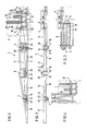
- Fig. 1
- das erfindungsgemäße Spritzgestänge in seiner Spritzstellung in Prinzipdarstellung und in der Ansicht von hinten,
- Fig. 2
- das Spritzgestänge gemäß Fig. 1 in der Ansicht von oben,
- Fig. 3
- das Spritzgestänge teilweise zusammengeklappt in Prinzipdarstellung und in der Ansicht von oben und
- Fig. 4
- das Spritzgestänge in Transportstellung, in Prinzipdarstellung und in der Ansicht von hinten.
- Fig. 1
- the spray boom according to the invention in its spray position in a schematic representation and in the view from behind,
- Fig. 2
- 1 in the view from above,
- Fig. 3
- the sprayer boom partially folded in a schematic diagram and in the view from above and
- Fig. 4
- the spray boom in the transport position, in a schematic representation and in the view from behind.
Die Feldspritze weist den mit strichpunktierten Linien dargestellten Tank 1 mit einer Einfüllöffnung sowie einem nicht dargestellten Rahmen auf. Auf der Rückseite der Feldspritze ist an dem Rahmen der Feldspritze der Tragrahmen 2 des Spritzgestänges 3 in Höhenrichtung verstellbar und pendelnd in bekannter und daher nicht näher dargestellter Weise angeordnet. Das Spritzgestänge 3 ist in mehrere Abschnitte unterteilt, die mittels der Gelenke 4, 5, 6 und 7 miteinander verbunden sind. Der innerste Abschnitt 8 des Spritzgestänges 3 ist an dem Tragrahmen 2 mit dem Gelenk 4 angeordnet, dessen Schwenkachse etwa in Fahrtrichtung der Feldspritze verläuft. Die an den innersten Abschnitt 8 sich anschließenden Abschnitte 9, 10 und 11 des Spritzgestänges 3 sind jeweils um aufrechte Achsen verschwenkbar. Das in den Fig. 1 und 2 dargestellte Spritzgestänge 3 befindet sich in seiner gestreckten Lage, die der Arbeitsstellung entspricht.The field sprayer has the tank 1 shown with broken lines with a filling opening and a frame, not shown. On the rear of the field sprayer, the
Mittels der Gelenke 4, 5, 6 und 7 ist das Spritzgestänge 3 in eine zusammengefaltete Lage, über die in Fig. 3 dargestellte Stellung in die in Fig. 4 dargestellte zusammengefaltet Stellung, die der Transportstellung entspricht, zu bringen. Dieses geschieht über eine als Seilsteuerung ausgebildete Fernbedienungsvorrichtung.By means of the
Die als Seilsteuerung 12 ausgebildete Fernbedienungsvorrichtung weist das Einklappseil 13 und das Ausklappseil 14 auf. Das Einklappseil 13 und das Einklappseil 14 sind jeweils in einem Abstand von dem Gelenk 7 an dem äußersten Abschnitt 11 des Spritzgestänges 3 befestigt. Außerdem sind das Einklappseil 13 und das Ausklappseil 14 am Tragrahmen 2 befestigt. Es wäre jedoch auch möglich, daß das jeweilige Einklappseil 13 bzw. das jeweilige Ausklappseil 14 der beiden Seiten des Spritzgestänges 3 jeweils miteinander verbunden sind. Weiterhin sind am Tragrahmen 2 die als Einklappzylinder 15 und Ausklappzylinder 16 ausgebildeten Bedienungsvorrichtungen der Seilsteuerung 12 angeordnet. Der Einklappzylinder 15 und der Ausklappzylinder 16 sind als einfach wirkende Hydraulikzylinder ausgebildet.The remote control device designed as a
Zwischen den einzelnen Anschnitten 8, 9, 10 und 11 des Spritzgestänges 3 sind Seilführungselemente angeordnet, die die Seile 13 und 14 in einem Abstand von der Schwenkachse der jeweilige Gelenke 4, 5, 6 und 7 halten. An dem innersten Teil 8 des Spritzgestänges 3 ist oberhalb des Gelenkes 4 der über das Gelenk 4 nach oben überstehende Arm 17 angeordnet. Dieser Arm 17 weist an seinem oberen Ende das als Seilrolle 18 ausgebildete Seilführungselement auf. Diese Seilrolle 18 ist frei drehbar an dem Arm 17 gelagert. Zwischen den Abschnitten 8 und 9 sind in dem Gelenk 5 die als Seilrollen 19 ausgebildeten Seilführungselemente angeordnet, die auf dem Gelenkbolzen des Gelenkes 5 frei drehbar gelagert sind. Weiterhin sind an den Abschnitten 8 und 9 des Spritzgestänges 3 im Bereich des Gelenkes 5 die beiden kleinen Seilrollen 20 zur Umlenkung des Ausklappseiles 16 angeordnet. Auch diese Seilrollen 20 sind frei drehbar angeordnet. Zwischen den Abschnitten 9 und 10 sind die beiden als Seilrollen 21 ausgebildeten Seilführungselemente auf dem Gelenkbolzen des Gelenkes 6 frei drehbar angeordnet. Zwischen den einzelnen Abschnitten 10 und 11 sind die als Seilrollen 22 und 23 ausgebildeten Seilführungselemente frei drehbar auf dem Gelenkbolzen des Gelenkes 7 angeordnet.Rope guiding elements are arranged between the
Das Einklappseil 13 ist an dem äußersten Abschnitt 11 des Spritzgestänges 3 befestigt. Das Einklappseil 13 ist dann um die große Seilrolle 23, die auf dem Gelenkbolzen des Gelenkes 7 gelagert ist, herumgeführt. Anschließend ist das Einklappseil 13 um die kleine Seilrolle 24, die frei drehbar im äußeren Bereich des Abschnittes 10 angeordnet ist, herumgeführt. Anschließend ist das Einklappseil 13 um die kleine Seilrolle 25, die im inneren Bereich des Abschnittes 10 des Spritzgestänges 3 frei drehbar gelagert ist, herumgeführt. Anschließend ist das Einklappseil 13 um die untere Rolle 21 herumgeführt. Anschließend wird das Einklappseil 13 durch die Seilrolle 26, die im äußeren Bereich an dem Abschnitt 9 frei drehbar gelagert ist, herumgeführt. Anschließend wird das Einklappseil 13 um die freidrehbar an dem inneren Bereich des Abschnittes 9 gelagerten Rolle 27 herumgeführt, bevor es um die Rolle 19 und die an dem inneren Bereich des Abschnittes 8 freidrehbar angeordneten Seilrolle 28 herumgeführt wird. Anschließend wird das Einklappseil 13 um die in der Nähe des Gelenkes 4 angeordneten und frei drehbar gelagerten Rolle 29 herumgeführt, bevor das Einklappseil 13 über die Seilrolle 18 herumgeführt wird. Anschließend wird das Einklappseil 13 um die an dem Tragrahmen 2 angeordneten Seilrolle 30 umgelenkt. Nach der Seilrolle 30 wird das Einklappseil 13 über die an dem Einklappzylinder 15 angeordneten Umlenkrolle 31 herumgeführt und an dem Tragrahmen 2 befestigt.The
Das Ausklappseil 13 ist in einem Abstand von dem Gelenk 7 an dem äußeren Abschnitt 11 befestigt. Während des Einklappens des Gestänges legt das Ausklappseil 14 sich um die kleine Seilrolle 22. Bevor das Ausklappseil 14 über die im inneren Bereich des Abschnittes 10 frei drehbar gelagerte Seilrolle 32 ist in dem Ausklappseil 14 die Zugfeder 33 angeordnet. Weiterhin ist das Ausklappseil 14 über die in dem äußeren Bereich des Abschnittes 9 angeordnete Seilrolle 34 geführt. Wenn das Spritzgestänge 3 eingeklappt wird, legt das Ausklappseil 14 sich in dem Bereich des Gelenkes 6 um die untere Seilrolle 21, die auf dem Gelenkbolzen des Gelenkes 6 angeordnet ist. Des weiteren ist das Ausklappseil 14 falschenzugartig über die Seilrollen 35 und 36 geführt. Die Seilrolle 34 ist in dem inneren Bereich des Abschnittes 9 angeordnet, während die Seilrolle 35 in dem äußeren Bereich des Abschnittes 8 frei drehbar gelagert ist. Während des Einklappens des Spritzgestänges 3 legt sich das Einklappseil 14, welches flaschenzugartig über die Rollen 34 und 35 geführt ist, um die oberen drei Seilrollen 19, die auf dem Gelenkbolzen des Gelenkes 5 angeordnet sind. Weiterhin ist das Einklappseil 14 um die Seilrolle 37, die an dem Tragrahmen 2 frei drehbar gelagert ist geführt. Weiterhin ist das Ausklappseil 14 um die an dem Ausklappzylinder 16 drehbar gelagerte Seilrolle 38 herumgeführt und mit seinem Ende an dem Tragrahmen 2 befestigt.The fold-out
Das Einklappseil 13 befindet sich jeweils auf der Seite des jeweiligen Gelenkes 5, 6 und 7 zu der die einander benachbarten Abschnitte 8, 9, 10 und 11 aneinander heranklappbar sind, während sich das Ausklappseil 14 jeweils sich auf der anderen Seite der Gelenke 5, 6, und 7 befindet. Durch diese Anordnung sind die Einklappseile 13 und die Ausklappseile 14 jeweils gegenläufig zueinander wirksam. Durch die unterschiedlich großen Rollen 22, 23, 21 sowie der flaschenzugartigen Seilumlenkung im Bereich des Gelenkes 5 sind die Ausklappmomente von innen nach außen aufbaubar, während die Einklappmomente von außen nach innen aufbaubar sind. Da die Einklappseile 13 und die Ausklappseile 14 gegenläufig wirksam sind, sowie an ihrem jeweiligen Ende an dem äußersten Abschnitt 11 befestigt sind, wird durch das AusKlappseil 14 eine Gegenkraft gegen die Kraft des Einklappseiles 13 beim Einklappen des Gestänges3 aufgebracht. Diese Gegenkraft rührt daher, daß in der Hydraulikleitung zu dem Ausklappzylinder 16 ein Drosselventil angeordnet ist und beim Einklappen des Spritzgestänges 3 über das Ausklappseil 14 der Ausklappzylinder 16 zusammengedrückt wird, indem über den Einklappzylinder 15 und das Einklappseil 13 das Spritzgestänge 3 zusammengeklappt wird.The
Das Einklappen bzw. das Ausklappen des Spritzgestänges geschieht folgendermaßen:The sprayer booms are folded in or out as follows:
Wenn das Spritzgestänges 3 gemäß Fig. 1 sich in der Spritzstellung befindet und in die Transportstellung gebracht werden soll, wird über einen hydraulischen Bedienungshebel der mit der Schlepperhydraulikanlage verbundene Einklappzylinder 13 ausgefahren. Durch das Ausfahren des Einklappzylinders 13 wird das Einklappseil im Bereich des Spritzgestänges 3 verkürzt. Zunächst werden beim Einklappen die Abschnitte 11 um 180° nach hinten an den Abschnitt 10 des Verteilergestänges 3 herangeklappt. Wenn jeweils der Abschnitt 11 an den jeweiligen Abschnitt 10 herangeklappt ist, werden die Abschnitte 10 und 11 gemeinsam nach vorn um 108° an den Abschnitt 9 des Spritzgestänges 3 herangeklappt. Wenn der Abschnitt 10 mit dem Abschnitt 11 an dem Abschnitt 9 des Spritzgestänges 3 anliegt, werden die Abschnitte 9, 10 und 11 gemeinsam um das Gelenk 9 nach hinten an den Abschnitt 8 des Spritzgestänges 3 herangeklappt. Wenn nun der Abschnitt 9 an dem Abschnitt 8 des Spritzgestänges 3 zur Anlage kommt, und so die Abschnitte 8, 9, 10 und 11 ein kompaktes Paket, wie in Fig. 3 dargestellt, bilden, wird dieses Paktet der Abschnitte 8, 9, 10 und 11 aus der in Fig. 3 dargestellten Position in die in Fig. 4 dargestellte Position geklappt. Hierbei sind die Einklappseile 13 und die Ausklappseile 14 so geführt, daß gleichzeitig die beiden seitlich der Feldspritze gelegenen Abschnitte des Spritzgestänges 3 gleichzeitig zusammengefaltet werden.If the
Soll das Spritzgestänge aus der in Fig. 4 dargestellten Transportstellung in die in Fig. 1 dargestellte Arbeitsstellung gebracht werden, so wird über ein Hydraulikventil der mit der Schlepperhydraulikanlage verbundene Ausklappzylinder 14 mit Druck beaufschlagt. Durch das Ausfahren des Ausklappzylinders 16 wird an dem Ausklappseil 14 gezogen. Gleichzeitig wird über dem Ausleger 11, an dem gemeinsam das Ein- und das Ausklappseil befestigt sind, an dem Einklappseil 13 gezogen, so daß der Einklappzylinder 15 zusammengedrückt wird. Durch das Ausfahren des Ausklappzylinders 16 wird das Spritzgestänge 3 zunächst in die in Fig. 3 dargestellte Position um die durch das Gelenk 4 verlaufende Schwenkachse geschwenkt. Anschließend schwenken die Abschnitte 9, 10 und 11 des Spritzgestänges um das Gelenk 5 um 180° in eine Stellung, die in Verlängerung des Abschnittes 8 des Spritzgestänges 3 liegt. Wenn der Abschnitt 9 in Verlängerung des Abschnittes 8 liegt, klappen die Abschnitte 10 und 11 um das Gelenk 6 um 180° in eine Stellung, die in Verlängerung der Abschnitte 8 und 9 des Spritzgestänges liegt. Anschließend klappt der Abschnitt 11 um das Gelenk 7 in die in Fig. 2 dargestellte Position. Somit befindet sich das Spritzgestänge 3 in der Arbeitsstellung.If the spray boom is to be brought from the transport position shown in FIG. 4 into the working position shown in FIG. 1, the fold-out
Claims (13)
- Agricultural field sprayer, including a spray boom (3), which is divided into at least three sections (8, 9, 10, 11) on each side of extension, said sections being interconnected by means of pivot Joints (4, 5, 6, 7), pivotal axles of which extend vertically, and being capable of being brought into an extended position (operative position) and into a retracted position (travelling position), wherein the individual sections (8, 9, 10, 11) can be brought from their operative position into their travelling position, and vice versa, through the intermediary of a remote control device (12), characterised in that the remote control device is in the form of a cable control means (12), in that each cable (13, 14) of the cable control means (12) is secured only to the outermost section (11) of the spray boom (3) and to a cable pulling member (15, 16), which is disposed on the frame (2) of the field Sprayer, and in that cable guiding members (18, 19, 20, 21, 22, 23, 24, 25, 26, 27, 28, 29, 30, 32, 34, 35, 36, 37) are disposed between the individual sections in the region of the respective pivot Joints (4, 5, 6, 7) and keep the cable (13, 14) at a spacing from the pivotal axle of the pivot joints (4, 5, 6, 7).
- Field sprayer according to claim 1, characterised in that the pivotal axles of the inner pivot Joints (4), by means of which the innermost sections (8) of the spray boom (3) are pivotally mounted on the frame of the field sprayer, each extend substantially in the direction of travel.
- Field sprayer according to claim 2, wherein the spray boom is retractable or extensible in a zig-zag-shaped manner, characterised in that two cables (13, 14) are provided for each side of the spray boom (3), the spray boom being retractable by pulling one cable, the retraction cable (13), and the spray boom (3) being extensible by pulling the other cable, the extension cable (14).
- Field sprayer according to claim 3, characterised in that the two cables are each disposed so that the retraction cable (13) is situated in each case on the side of the respective pivot joint (5, 6, 7), on which side the sections (8, 9, 10, 11) adjacent one another are foldable towards one another, while the extension cable (14) is situated in each case on the other side of the respective pivot joint (8, 9, 10, 11).
- Field sprayer according to claims 2 and 4, characterised in that, above the pivot Joint (4), which extends substantially in the direction of travel, the innermost section (8) is provided with an arm (17), which protrudes upwardly beyond the pivot joint, and in that the retraction cable (13) is guided through the intermediary of this arm (17).
- Field sprayer according to claim 1, characterised in that the arrangement for operating the cable control means is in the form of hydraulic cylinders (15, 16).
- Field sprayer according to claim 1, characterised in that the arrangement for operating the cable control means is in the form of a cable winch.
- Field sprayer according to claim 3, characterised in that the retraction cables (13) and the extension cables (14) are each operative in opposite directions to one another.
- Field sprayer according to claim 3, characterised in that the retraction cables (13) and the extension cables (14) for both sides of the spray boom are interconnected.
- Field sprayer according to claim 1, characterised in that the extension members are assemblable from internally outwardly, while the retraction members are assemblable from externally inwardly.
- Field sprayer according to claims 8 and 10, characterised in that, during the retraction movement, a counteracting force acting in opposition to the force of the retraction cable (13) can be applied by the extension cable (14), and in that, during the extension movement, a counteracting force acting in opposition to the force of the extension cable (14) can be applied by the retraction cable (13).
- Field sprayer according to claim 10, characterised in that the cables (14) are each disposed in a pulley-like manner between the inner sections (8,9) of the spray boom (3), while the cables between the outer sections (9, 10, 11) are substantially guided through the intermediary of different lever arms.
- Field sprayer according to claim 3, characterised in that a tension spring (33) is disposed in the extension cable (14) in the region of the outer sections (10, 11).
Applications Claiming Priority (2)
| Application Number | Priority Date | Filing Date | Title |
|---|---|---|---|
| DE19853541130 DE3541130A1 (en) | 1985-11-21 | 1985-11-21 | AGRICULTURAL SPRAYER WITH A SPRAYER |
| DE3541130 | 1985-11-21 |
Publications (3)
| Publication Number | Publication Date |
|---|---|
| EP0224166A2 EP0224166A2 (en) | 1987-06-03 |
| EP0224166A3 EP0224166A3 (en) | 1988-10-12 |
| EP0224166B1 true EP0224166B1 (en) | 1991-05-29 |
Family
ID=6286445
Family Applications (1)
| Application Number | Title | Priority Date | Filing Date |
|---|---|---|---|
| EP86115921A Expired - Lifetime EP0224166B1 (en) | 1985-11-21 | 1986-11-17 | Spraying boom for a field sprayer |
Country Status (2)
| Country | Link |
|---|---|
| EP (1) | EP0224166B1 (en) |
| DE (2) | DE3541130A1 (en) |
Families Citing this family (6)
| Publication number | Priority date | Publication date | Assignee | Title |
|---|---|---|---|---|
| US5178328A (en) * | 1991-12-18 | 1993-01-12 | The Broyhill Company | Folding boom for agricultural sprayers |
| AU719303B2 (en) * | 1998-09-14 | 2000-05-04 | Bent Baek | Agriculture/viticulture sprayer |
| US7431221B2 (en) | 2005-05-16 | 2008-10-07 | Cnh Canada, Ltd. | Lock assembly for a multiple stage folding boom assembly |
| CN101837330A (en) * | 2010-05-17 | 2010-09-22 | 华南农业大学 | Diagonal cable type based of spraying machine spray bar mechanism based on diagonal tension cable support |
| US9839211B2 (en) * | 2014-08-11 | 2017-12-12 | Deere & Company | Segmented boom system for work vehicle |
| AT521966B1 (en) | 2019-02-15 | 2020-07-15 | Georg Unger Dr | Mobile irrigation system |
Citations (1)
| Publication number | Priority date | Publication date | Assignee | Title |
|---|---|---|---|---|
| DE1859848U (en) * | 1962-06-09 | 1962-10-11 | Otto Quentin | SPRAY DEVICE. |
Family Cites Families (7)
| Publication number | Priority date | Publication date | Assignee | Title |
|---|---|---|---|---|
| US3055594A (en) * | 1960-01-04 | 1962-09-25 | Burg Mfg Company | Boom type spraying means |
| FR1455965A (en) * | 1964-07-29 | 1966-05-20 | H J Hoegen Dijkhof G M B H | Device mounted on a vehicle for spraying insecticides |
| FR2460438B2 (en) * | 1978-12-11 | 1986-05-09 | Evrard Ets | DEVICE FOR THE STABILITY OF SPRAYING RAMPS |
| FR2450035A1 (en) * | 1979-02-28 | 1980-09-26 | Mahe Jean | Boom for agricultural spraying - has double section arm raised and folded each side of centre using single hydraulic cylinder and cable |
| DE3025175C2 (en) * | 1980-07-03 | 1981-10-01 | Amazonen-Werke H. Dreyer Gmbh & Co Kg, 4507 Hasbergen | Distributor with booms |
| DE3119093C2 (en) * | 1981-05-14 | 1984-05-30 | Maschinenfabrik Rau Gmbh, 7315 Weilheim | Sprayer |
| FR2560533A1 (en) * | 1984-03-01 | 1985-09-06 | Evrard Ets | Improvements to collapsible (folding) agricultural spray booms |
-
1985
- 1985-11-21 DE DE19853541130 patent/DE3541130A1/en not_active Withdrawn
-
1986
- 1986-11-17 EP EP86115921A patent/EP0224166B1/en not_active Expired - Lifetime
- 1986-11-17 DE DE8686115921T patent/DE3679512D1/en not_active Expired - Lifetime
Patent Citations (1)
| Publication number | Priority date | Publication date | Assignee | Title |
|---|---|---|---|---|
| DE1859848U (en) * | 1962-06-09 | 1962-10-11 | Otto Quentin | SPRAY DEVICE. |
Also Published As
| Publication number | Publication date |
|---|---|
| EP0224166A3 (en) | 1988-10-12 |
| EP0224166A2 (en) | 1987-06-03 |
| DE3679512D1 (en) | 1991-07-04 |
| DE3541130A1 (en) | 1987-05-27 |
Similar Documents
| Publication | Publication Date | Title |
|---|---|---|
| DE3925150C2 (en) | ||
| DE60127771T2 (en) | Bridge sundeck with cross connection between tower and vehicle frame | |
| DE2713270B2 (en) | Support beam for agricultural implements with at least one pivotable beam part | |
| DE1482373A1 (en) | Device for spraying pest control agents that can be attached to a vehicle | |
| DE10307149A1 (en) | Folding vehicle seat | |
| DE3735262C2 (en) | ||
| DE2751333A1 (en) | TELESCOPIC SAFETY DRAWBAR | |
| DE1962651A1 (en) | Vehicle conveyor system | |
| DE1481873A1 (en) | Load lifting device | |
| EP1770050B1 (en) | Foldable crane | |
| EP0317891A2 (en) | Apparatus for fighting high altitude fires | |
| DE2817650C2 (en) | ||
| EP0224166B1 (en) | Spraying boom for a field sprayer | |
| DE2834646A1 (en) | CHAIN GEAR WITH GEAR PRESET | |
| EP0037571A2 (en) | Distributing mast for a concrete pump | |
| DE3938867A1 (en) | AGRICULTURAL DISTRIBUTION MACHINE | |
| DE3921291A1 (en) | Agricultural field spray boom - has central locking or tensioning device | |
| DE60007488T2 (en) | Collapsing device of a crane jib with intermeshable elements | |
| DE3419427A1 (en) | Articulated crane | |
| DE2614223A1 (en) | BOOM ARRANGEMENT ON A TELESCOPIC MAST OF A TOWER CRANE | |
| DE3218525A1 (en) | Slope-mowing appliance | |
| DE2445965A1 (en) | SPRAY DEVICE FOR AGRICULTURAL PURPOSES | |
| EP0428963A1 (en) | Agricultural spreader | |
| EP0212235A2 (en) | Agricultural spraying apparatus with a spray boom | |
| EP0604681B1 (en) | Nozzleboom for raining upon especially agricultural surfaces |
Legal Events
| Date | Code | Title | Description |
|---|---|---|---|
| PUAI | Public reference made under article 153(3) epc to a published international application that has entered the european phase |
Free format text: ORIGINAL CODE: 0009012 |
|
| AK | Designated contracting states |
Kind code of ref document: A2 Designated state(s): BE DE FR GB NL |
|
| PUAL | Search report despatched |
Free format text: ORIGINAL CODE: 0009013 |
|
| AK | Designated contracting states |
Kind code of ref document: A3 Designated state(s): BE DE FR GB NL |
|
| 17P | Request for examination filed |
Effective date: 19880830 |
|
| 17Q | First examination report despatched |
Effective date: 19900727 |
|
| GRAA | (expected) grant |
Free format text: ORIGINAL CODE: 0009210 |
|
| AK | Designated contracting states |
Kind code of ref document: B1 Designated state(s): BE DE FR GB NL |
|
| ET | Fr: translation filed | ||
| REF | Corresponds to: |
Ref document number: 3679512 Country of ref document: DE Date of ref document: 19910704 |
|
| GBT | Gb: translation of ep patent filed (gb section 77(6)(a)/1977) | ||
| PGFP | Annual fee paid to national office [announced via postgrant information from national office to epo] |
Ref country code: BE Payment date: 19911112 Year of fee payment: 6 |
|
| PLBE | No opposition filed within time limit |
Free format text: ORIGINAL CODE: 0009261 |
|
| STAA | Information on the status of an ep patent application or granted ep patent |
Free format text: STATUS: NO OPPOSITION FILED WITHIN TIME LIMIT |
|
| 26N | No opposition filed | ||
| PGFP | Annual fee paid to national office [announced via postgrant information from national office to epo] |
Ref country code: GB Payment date: 19920821 Year of fee payment: 7 |
|
| PGFP | Annual fee paid to national office [announced via postgrant information from national office to epo] |
Ref country code: FR Payment date: 19921127 Year of fee payment: 7 |
|
| PG25 | Lapsed in a contracting state [announced via postgrant information from national office to epo] |
Ref country code: BE Effective date: 19921130 |
|
| PGFP | Annual fee paid to national office [announced via postgrant information from national office to epo] |
Ref country code: NL Payment date: 19921130 Year of fee payment: 7 |
|
| BERE | Be: lapsed |
Owner name: AMAZONEN-WERKE H. DREYER G.M.B.H. & CO. K.G. Effective date: 19921130 |
|
| PG25 | Lapsed in a contracting state [announced via postgrant information from national office to epo] |
Ref country code: GB Effective date: 19931117 |
|
| PGFP | Annual fee paid to national office [announced via postgrant information from national office to epo] |
Ref country code: DE Payment date: 19931124 Year of fee payment: 8 |
|
| PG25 | Lapsed in a contracting state [announced via postgrant information from national office to epo] |
Ref country code: NL Effective date: 19940601 |
|
| GBPC | Gb: european patent ceased through non-payment of renewal fee |
Effective date: 19931117 |
|
| NLV4 | Nl: lapsed or anulled due to non-payment of the annual fee | ||
| PG25 | Lapsed in a contracting state [announced via postgrant information from national office to epo] |
Ref country code: FR Effective date: 19940729 |
|
| REG | Reference to a national code |
Ref country code: FR Ref legal event code: ST |
|
| PG25 | Lapsed in a contracting state [announced via postgrant information from national office to epo] |
Ref country code: DE Effective date: 19950801 |