EP0604320A1 - Kraftstoffdampffiltervorrichtung und eine einer solchen Filtervorrichtung zugeordnete Anordnung zum Füllen eines Behälters - Google Patents
Kraftstoffdampffiltervorrichtung und eine einer solchen Filtervorrichtung zugeordnete Anordnung zum Füllen eines Behälters Download PDFInfo
- Publication number
- EP0604320A1 EP0604320A1 EP93403159A EP93403159A EP0604320A1 EP 0604320 A1 EP0604320 A1 EP 0604320A1 EP 93403159 A EP93403159 A EP 93403159A EP 93403159 A EP93403159 A EP 93403159A EP 0604320 A1 EP0604320 A1 EP 0604320A1
- Authority
- EP
- European Patent Office
- Prior art keywords
- cartridge
- housing
- filtration device
- filter element
- side wall
- Prior art date
- Legal status (The legal status is an assumption and is not a legal conclusion. Google has not performed a legal analysis and makes no representation as to the accuracy of the status listed.)
- Granted
Links
Images


Classifications
-
- B—PERFORMING OPERATIONS; TRANSPORTING
- B01—PHYSICAL OR CHEMICAL PROCESSES OR APPARATUS IN GENERAL
- B01D—SEPARATION
- B01D53/00—Separation of gases or vapours; Recovering vapours of volatile solvents from gases; Chemical or biological purification of waste gases, e.g. engine exhaust gases, smoke, fumes, flue gases, aerosols
- B01D53/02—Separation of gases or vapours; Recovering vapours of volatile solvents from gases; Chemical or biological purification of waste gases, e.g. engine exhaust gases, smoke, fumes, flue gases, aerosols by adsorption, e.g. preparative gas chromatography
- B01D53/04—Separation of gases or vapours; Recovering vapours of volatile solvents from gases; Chemical or biological purification of waste gases, e.g. engine exhaust gases, smoke, fumes, flue gases, aerosols by adsorption, e.g. preparative gas chromatography with stationary adsorbents
- B01D53/0407—Constructional details of adsorbing systems
- B01D53/0415—Beds in cartridges
-
- B—PERFORMING OPERATIONS; TRANSPORTING
- B60—VEHICLES IN GENERAL
- B60K—ARRANGEMENT OR MOUNTING OF PROPULSION UNITS OR OF TRANSMISSIONS IN VEHICLES; ARRANGEMENT OR MOUNTING OF PLURAL DIVERSE PRIME-MOVERS IN VEHICLES; AUXILIARY DRIVES FOR VEHICLES; INSTRUMENTATION OR DASHBOARDS FOR VEHICLES; ARRANGEMENTS IN CONNECTION WITH COOLING, AIR INTAKE, GAS EXHAUST OR FUEL SUPPLY OF PROPULSION UNITS IN VEHICLES
- B60K15/00—Arrangement in connection with fuel supply of combustion engines or other fuel consuming energy converters, e.g. fuel cells; Mounting or construction of fuel tanks
- B60K15/03—Fuel tanks
- B60K15/035—Fuel tanks characterised by venting means
- B60K15/03504—Fuel tanks characterised by venting means adapted to avoid loss of fuel or fuel vapour, e.g. with vapour recovery systems
-
- B—PERFORMING OPERATIONS; TRANSPORTING
- B60—VEHICLES IN GENERAL
- B60K—ARRANGEMENT OR MOUNTING OF PROPULSION UNITS OR OF TRANSMISSIONS IN VEHICLES; ARRANGEMENT OR MOUNTING OF PLURAL DIVERSE PRIME-MOVERS IN VEHICLES; AUXILIARY DRIVES FOR VEHICLES; INSTRUMENTATION OR DASHBOARDS FOR VEHICLES; ARRANGEMENTS IN CONNECTION WITH COOLING, AIR INTAKE, GAS EXHAUST OR FUEL SUPPLY OF PROPULSION UNITS IN VEHICLES
- B60K15/00—Arrangement in connection with fuel supply of combustion engines or other fuel consuming energy converters, e.g. fuel cells; Mounting or construction of fuel tanks
- B60K15/03—Fuel tanks
- B60K15/04—Tank inlets
-
- F—MECHANICAL ENGINEERING; LIGHTING; HEATING; WEAPONS; BLASTING
- F02—COMBUSTION ENGINES; HOT-GAS OR COMBUSTION-PRODUCT ENGINE PLANTS
- F02M—SUPPLYING COMBUSTION ENGINES IN GENERAL WITH COMBUSTIBLE MIXTURES OR CONSTITUENTS THEREOF
- F02M25/00—Engine-pertinent apparatus for adding non-fuel substances or small quantities of secondary fuel to combustion-air, main fuel or fuel-air mixture
- F02M25/08—Engine-pertinent apparatus for adding non-fuel substances or small quantities of secondary fuel to combustion-air, main fuel or fuel-air mixture adding fuel vapours drawn from engine fuel reservoir
- F02M25/0854—Details of the absorption canister
-
- B—PERFORMING OPERATIONS; TRANSPORTING
- B01—PHYSICAL OR CHEMICAL PROCESSES OR APPARATUS IN GENERAL
- B01D—SEPARATION
- B01D2253/00—Adsorbents used in seperation treatment of gases and vapours
- B01D2253/10—Inorganic adsorbents
- B01D2253/102—Carbon
-
- B—PERFORMING OPERATIONS; TRANSPORTING
- B01—PHYSICAL OR CHEMICAL PROCESSES OR APPARATUS IN GENERAL
- B01D—SEPARATION
- B01D2257/00—Components to be removed
- B01D2257/70—Organic compounds not provided for in groups B01D2257/00 - B01D2257/602
- B01D2257/702—Hydrocarbons
-
- B—PERFORMING OPERATIONS; TRANSPORTING
- B01—PHYSICAL OR CHEMICAL PROCESSES OR APPARATUS IN GENERAL
- B01D—SEPARATION
- B01D2257/00—Components to be removed
- B01D2257/80—Water
-
- B—PERFORMING OPERATIONS; TRANSPORTING
- B01—PHYSICAL OR CHEMICAL PROCESSES OR APPARATUS IN GENERAL
- B01D—SEPARATION
- B01D2258/00—Sources of waste gases
- B01D2258/01—Engine exhaust gases
-
- B—PERFORMING OPERATIONS; TRANSPORTING
- B01—PHYSICAL OR CHEMICAL PROCESSES OR APPARATUS IN GENERAL
- B01D—SEPARATION
- B01D2259/00—Type of treatment
- B01D2259/45—Gas separation or purification devices adapted for specific applications
- B01D2259/4516—Gas separation or purification devices adapted for specific applications for fuel vapour recovery systems
-
- B—PERFORMING OPERATIONS; TRANSPORTING
- B01—PHYSICAL OR CHEMICAL PROCESSES OR APPARATUS IN GENERAL
- B01D—SEPARATION
- B01D2259/00—Type of treatment
- B01D2259/45—Gas separation or purification devices adapted for specific applications
- B01D2259/4566—Gas separation or purification devices adapted for specific applications for use in transportation means
-
- B—PERFORMING OPERATIONS; TRANSPORTING
- B01—PHYSICAL OR CHEMICAL PROCESSES OR APPARATUS IN GENERAL
- B01D—SEPARATION
- B01D53/00—Separation of gases or vapours; Recovering vapours of volatile solvents from gases; Chemical or biological purification of waste gases, e.g. engine exhaust gases, smoke, fumes, flue gases, aerosols
- B01D53/02—Separation of gases or vapours; Recovering vapours of volatile solvents from gases; Chemical or biological purification of waste gases, e.g. engine exhaust gases, smoke, fumes, flue gases, aerosols by adsorption, e.g. preparative gas chromatography
- B01D53/04—Separation of gases or vapours; Recovering vapours of volatile solvents from gases; Chemical or biological purification of waste gases, e.g. engine exhaust gases, smoke, fumes, flue gases, aerosols by adsorption, e.g. preparative gas chromatography with stationary adsorbents
- B01D53/0407—Constructional details of adsorbing systems
- B01D53/0438—Cooling or heating systems
-
- B—PERFORMING OPERATIONS; TRANSPORTING
- B01—PHYSICAL OR CHEMICAL PROCESSES OR APPARATUS IN GENERAL
- B01D—SEPARATION
- B01D53/00—Separation of gases or vapours; Recovering vapours of volatile solvents from gases; Chemical or biological purification of waste gases, e.g. engine exhaust gases, smoke, fumes, flue gases, aerosols
- B01D53/02—Separation of gases or vapours; Recovering vapours of volatile solvents from gases; Chemical or biological purification of waste gases, e.g. engine exhaust gases, smoke, fumes, flue gases, aerosols by adsorption, e.g. preparative gas chromatography
- B01D53/04—Separation of gases or vapours; Recovering vapours of volatile solvents from gases; Chemical or biological purification of waste gases, e.g. engine exhaust gases, smoke, fumes, flue gases, aerosols by adsorption, e.g. preparative gas chromatography with stationary adsorbents
- B01D53/0454—Controlling adsorption
-
- B—PERFORMING OPERATIONS; TRANSPORTING
- B01—PHYSICAL OR CHEMICAL PROCESSES OR APPARATUS IN GENERAL
- B01D—SEPARATION
- B01D53/00—Separation of gases or vapours; Recovering vapours of volatile solvents from gases; Chemical or biological purification of waste gases, e.g. engine exhaust gases, smoke, fumes, flue gases, aerosols
- B01D53/26—Drying gases or vapours
- B01D53/261—Drying gases or vapours by adsorption
Definitions
- the present invention relates to a device for filtering fuel vapors.
- the invention relates more particularly to a filtration device which is intended to be integrated in the fuel supply circuit of an internal combustion engine of a motor vehicle which is also known under the name of "canister".
- a filtration device of this type is to absorb gasoline vapors in order to suppress releases into the atmosphere of hydrocarbons due to evaporation losses which occur in particular at the top of the vehicle fuel tank.
- the canister recovers and provides transient storage of gasoline vapors escaping from the tank.
- the canister gradually loses its effectiveness.
- the invention provides a filtration device, or canister, of the type mentioned above, characterized in that the filter element is produced in the form of a cartridge filter element which can be replaced when it is clogged.
- the invention also provides a filter element cartridge for a fuel vapor filtration device produced in accordance with the teachings of the invention, the open upper face of the cartridge being, before its use, closed by a cover.
- the cartridge is likely to undergo a regeneration cycle of the used filter element with a view to its reuse.
- the invention also relates to an arrangement for filling a motor vehicle fuel tank of the type comprising a filling pipe, the filling orifice of which is arranged in a zone of the vehicle accessible to a user.
- the filling pipe ends at its upper part with a filling head which opens out at the rear part of the vehicle, for example at a rear lateral wing, and which is equipped with 'a closing device itself accessible by a hatch of the body.
- This arrangement is particularly advantageous insofar as the fuel tank is itself arranged at the rear part of the vehicle, generally between the floor and the rear seats, and it makes it possible to reduce the length of the filling pipe.
- the fuel tank is equipped with a vent pipe which opens into a fuel vapor filtration device which it is necessary to fit into the vehicle and which, in accordance with the teachings of the invention, may have a filter cartridge which must be replaced regularly.
- This accessory therefore also needs to be arranged in a relatively accessible area of the vehicle so as not to overly complicate the operations. necessary to replace the filter cartridge, as well as to check its clogging state.
- the object of the invention is to propose an arrangement which makes it possible to solve the problems which have just been mentioned in a simple and economical manner.
- the invention provides an arrangement for filling a fuel tank of a motor vehicle, of the type comprising a filling tube whose filling orifice is arranged in an area of the vehicle accessible to a user, characterized in that it comprises at least one filtration device produced in accordance with the teachings of the invention, with a cartridge of filter element, which is connected to the filling pipe and whose connection head is arranged near the orifice filling, in said area of the vehicle.
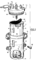
- the filtration device, or canister, illustrated in FIG. 1 comprises a connection head 10 which is mounted and fixed in leaktight manner on the open upper face 12 of a lower part 14 in the form of a housing.
- connection head 10 and the housing 14 are generally cylindrical in shape with a vertical axis when considering FIG. 1.
- the housing 14 is partially constituted by a canister filter element cartridge which has a cylindrical side wall 16, the upper end of which is provided with a radial collar 18, the open upper face 12 of which bears against the lower face 20 of the connection head 10.
- a sealing O-ring 22 is interposed between these two bearing surfaces and the fixing of the connection head 10 on the housing 14 is ensured by means of a lateral clamp 24 which encloses the radial collar 18 of the casing 16 and a complementary collar 26 formed at the lower part of the connection head 10.
- the casing 16 in the form of a cylindrical skirt of the cartridge C is surrounded by a heating jacket 28 making it possible to preheat the filter element contained in the cartridge C.
- the lower end 30 of the envelope 16 of the cartridge C comprises a thread 32 allowing the fixing by screwing of a bottom 34 of the housing with the interposition of an O-ring seal 36.
- the bottom 34 is conically shaped to provide a decanting function for the liquid fuel contained in the cartridge C and it includes a bleed screw 38.
- the cartridge C contains a mass of filter element 40 which is for example an activated carbon and, at its upper and lower ends, two layers of foam 42 and 44.
- filter element 40 which is for example an activated carbon and, at its upper and lower ends, two layers of foam 42 and 44.
- a visual indicator 46 which allows to indicate the level of clogging and wear of the filter element 40 contained in the cartridge C.
- connection head 10 has an orifice connected to a pipe 48 for introducing gases loaded with hydrocarbon vapors which is connected to a nozzle 50 which penetrates into the filter material 40 of the cartridge C with the interposition of a valve 52.
- connection head 10 also includes a vapor evacuation orifice connected to an evacuation pipe 54 with the interposition of a valve 56.
- the ventilation of the filter element cartridge C is ensured by two venting arrangements.
- a first venting arrangement, of the canister in the direction of the outside, consists of a pipe 58 and a valve 60.
- the second venting device from the outside to the inside of the canister, is constituted by a pipe 62 in which a filtration device 64 can be arranged, intended to protect the activated carbon of the cartridge C from any moisture penetration.
- the various orifices and passages formed in the drive head all emerge in its lower face 20 above the upper face of the foam layer 42 of the cartridge C, or, in the case of the end piece 50, directly at inside the filter material 40.
- the canister illustrated in FIG. 1 operates in the following manner.
- the hydrocarbon molecules are adsorbed by the activated carbon.
- Adsorption is a reversible physical phenomenon which consists of an attachment of gases to solid surfaces according to the Van Der Waal force principle.
- the vacuum in the circuit causes “desorption”, that is to say the “detachment” of the gas molecules from the surfaces of the activated carbon and their evacuation from the canister for their injection into the circuit d motor power.
- a clogging indicator also called saturation indicator
- saturation indicator which can for example be produced in the form of a reactive paper
- It may be a hydrocarbon sensor which, placed in the cartridge, detects a concentration threshold of the hydrocarbons that the activated carbon can no longer restore after adsorption, thus making the desorption ineffective.
- the possibility of providing a preheating system for the filter element promotes the adsorption of hydrocarbons on the surface of the activated carbon.
- FIG. 2 The second embodiment illustrated in FIG. 2 will now be described in which components identical or similar to those of the embodiment illustrated in FIG. 1 are designated by the same reference numbers.
- the casing 14 is produced in the form of a self-contained metal casing which has its own casing 70 in the thickness of which are arranged heating conductive wires 72.
- the filter element cartridge C also has its own envelope constituted by its side wall 16 and by a closed bottom 74.
- the side wall 70 of the housing 14 has a window 76 to allow the clogging indicator 46 to be seen when the cartridge is in position in the housing 14.
- a compression spring 78 is arranged inside the housing 14 between the bottom 34 of the latter and the bottom 74 of the cartridge C.
- the open upper face 12 of the cartridge C can initially be closed by a protective cover 80.
- the O-ring seal 22 is here arranged in a groove formed in a portion of cylindrical side wall 82 of the lower part of the connection head 10 which is received in a sealed manner inside the complementary cylindrical upper part 84 of the side wall 70 of the housing 14.
- the cartridge constitutes a complete autonomous element whose body or envelope only ensures the conditioning of the activated carbon 40 contained in the cartridge C.
- This envelope is not subjected to any requirement concerning its permeability.
- the fixing of the canister to a part of the structure of the motor vehicle can be ensured by different fixing means such as for example the legs 86 and screws 88 illustrated in the figure, the housing 14, which is for example metallic, having for this purpose sufficient rigidity.
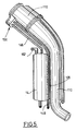
- the tubing 110 ends at its upper part with a filling pipe 112 whose free edge 114 can for example be made with an external thread (not shown) to receive a closure plug.
- the pipe 112 comprises a collar 116 for its attachment to the corresponding part of the body of the motor vehicle as well as a collar 118 which is used to hold in place a conduit 120, itself connected to the fuel tank which is also called the overfilling prohibition pipe.
- the filling tube 110 is associated, in the vicinity of its upper end, with a filtration device produced in accordance with the teachings of the invention, the housing 14 of which comprises a connection head 10 and means 138 for the connection of the filtration device to a pipe (not shown) for venting the fuel tank.
- connection head 10 of the housing 14 may comprise different pipes and connection pipes as in the case of a filtration device illustrated in Figures 1 and 2 (not shown).
- connection head 10 forming a plug extends substantially in the same plane as the filling orifice 114 of the tube 110.
- connection head 110 is produced in the form of a removable plug to allow the extraction and replacement of the filter element cartridge when the latter is clogged.
- tubing 110 and the housing 114 are made integrally as well as the collars 116 and 118 which are common to the two elements.
- the filling tube 110 and the housing 14 are made in the form of two independent elements, the housing 14 of the filtration device being fixed to the tube 110 by fixing lugs 86 which are for example glued or heat-sealed.
- the housing 14 and the filling pipe 110 are produced integrally in a single element, for example by the injection-blowing technique, and are interconnected by a rib 129.
- the admission of gases loaded with fuel vapors into the housing 14 is done by an upper pipe 146 which is connected to the main pipe 148 for venting the upper part of the fuel tank by a device, which n 'is not illustrated in detail in Figure 5, which may include a valve, controlled by the closure cap of the filling stack 112, which interrupts the communication between the lines 146 and 148.
- the evacuation of the filtered gases can be done by an outlet pipe 152 arranged at the upper part of the housing 14.
- a part 150 of the body of the motor vehicle is shown, for example arranged in the right rear side wing of the vehicle which can be closed by a hinged access door 154.
- the zone 151 allows access to a cap 155 for filling the fuel tank, which is screwed onto the threaded end 114 of the pipe 112 of the filling pipe 110.
- the zone 151 also includes a flap 156 which is illustrated in the closed position, and which allows on the one hand access to the upper part of the housing 14 containing a cartridge of filter element, and on the other hand the verification of the level d wear or clogging of the filter element cartridge.
- the flap 156 comprises fixing lugs 158 and locking bolts controlled by quarter-turn screws 160, as well as a window 162 arranged opposite a tell-tale 164 of clogging of the element cartridge. filtration.
- the access zone 151 in cooperation with the flap 156, can also delimit a slot 158 for the evacuation of the filtered gases.
- the user can therefore, for example during each filling of his tank, check through window 162 the clogging state of the filtration cartridge and proceed to its replacement for example when the indicator 164 is red as indicated on the inside face of the hatch 154.
Landscapes
- Engineering & Computer Science (AREA)
- Chemical & Material Sciences (AREA)
- Combustion & Propulsion (AREA)
- Mechanical Engineering (AREA)
- Life Sciences & Earth Sciences (AREA)
- Sustainable Development (AREA)
- Sustainable Energy (AREA)
- Transportation (AREA)
- Analytical Chemistry (AREA)
- General Chemical & Material Sciences (AREA)
- Oil, Petroleum & Natural Gas (AREA)
- Chemical Kinetics & Catalysis (AREA)
- General Engineering & Computer Science (AREA)
- Cooling, Air Intake And Gas Exhaust, And Fuel Tank Arrangements In Propulsion Units (AREA)
Applications Claiming Priority (4)
| Application Number | Priority Date | Filing Date | Title |
|---|---|---|---|
| FR9215640 | 1992-12-23 | ||
| FR9215640A FR2699464B1 (fr) | 1992-12-23 | 1992-12-23 | Agencement pour le remplissage d'un réservoir de carburant de véhicule automobile. |
| FR9309039A FR2707931B1 (fr) | 1993-07-22 | 1993-07-22 | Dispositif de filtration de vapeurs de carburant et cartouche d'élément filtrant pour un tel dispositif. |
| FR9309039 | 1993-07-22 |
Publications (2)
| Publication Number | Publication Date |
|---|---|
| EP0604320A1 true EP0604320A1 (de) | 1994-06-29 |
| EP0604320B1 EP0604320B1 (de) | 1997-03-12 |
Family
ID=26229987
Family Applications (1)
| Application Number | Title | Priority Date | Filing Date |
|---|---|---|---|
| EP19930403159 Expired - Lifetime EP0604320B1 (de) | 1992-12-23 | 1993-12-23 | Anordnung zum Füllen eines Behälters mit einer Kraftstoffdampffiltervorrichtung |
Country Status (3)
| Country | Link |
|---|---|
| EP (1) | EP0604320B1 (de) |
| DE (1) | DE69308791T2 (de) |
| ES (1) | ES2100499T3 (de) |
Cited By (7)
| Publication number | Priority date | Publication date | Assignee | Title |
|---|---|---|---|---|
| EP0685357A2 (de) * | 1994-05-31 | 1995-12-06 | EXPERT Maschinenbau GmbH | Aktivkohlefilter für Kraftfahrzeuge |
| FR2736878A1 (fr) * | 1995-07-04 | 1997-01-24 | Mc Micro Compact Car Ag | Reservoir de carburant et procede pour le fabriquer |
| EP0756079A1 (de) * | 1995-07-26 | 1997-01-29 | Toyota Jidosha Kabushiki Kaisha | Behälter für Tankentlüftungssystem |
| EP0822110A3 (de) * | 1996-07-30 | 1999-07-14 | ERGOM MATERIE PLASTICHE S.p.A | Kraftstoffeinfüllstutzen-Modul für Kraftfahrzeug |
| JP2006524606A (ja) * | 2003-04-30 | 2006-11-02 | イネルジー オートモーティヴ システムズ リサーチ | 燃料系統用の添加物リザーバ及びこのようなリザーバを製造する方法 |
| EP2110361A3 (de) * | 2008-04-14 | 2010-10-27 | Delphi Technologies, Inc. | Kartuschenaufnahmesystem zum Entfernen von Schwefelwasserstoff aus Reformaten |
| CN105626319A (zh) * | 2014-11-26 | 2016-06-01 | 现代自动车株式会社 | 用于碳罐的可插式过滤器以及具有该过滤器的碳罐 |
Families Citing this family (1)
| Publication number | Priority date | Publication date | Assignee | Title |
|---|---|---|---|---|
| CN111927660B (zh) * | 2020-08-20 | 2022-02-08 | 江西迈动智能装备有限公司 | 汽车发动机滤芯填充机 |
Citations (12)
| Publication number | Priority date | Publication date | Assignee | Title |
|---|---|---|---|---|
| US3748829A (en) * | 1970-07-02 | 1973-07-31 | Calgon Corp | Adsorbing evaporative emission during fueling of automotive vehicles |
| US4381929A (en) * | 1980-04-25 | 1983-05-03 | Nippon Soken, Inc. | Apparatus for adsorbing fuel vapor |
| DE3209007C1 (de) * | 1982-03-12 | 1983-08-25 | Daimler-Benz Ag, 7000 Stuttgart | Vorrichtung zum Betanken von Kraftfahrzeugen die sowohl mit Benzin als auch mit Flüssiggas zu betreiben sind |
| US4572394A (en) * | 1984-04-06 | 1986-02-25 | Toyota Jidosha Kabushiki Kaisha | Fuel tank for use in a motor vehicle |
| EP0245613A1 (de) * | 1986-05-14 | 1987-11-19 | Dr.Ing.h.c. F. Porsche Aktiengesellschaft | Kraftstoffbehälter für Kraftfahrzeuge mit einem Einfüllstutzen |
| US4732588A (en) * | 1987-05-14 | 1988-03-22 | General Motors Corporation | Canister using thermoelectric cooler |
| DE3709424A1 (de) * | 1987-03-21 | 1988-09-29 | Hauni Werke Koerber & Co Kg | Vorrichtung zum zerlegen eines gas-gemisches |
| WO1988009694A1 (en) * | 1987-06-01 | 1988-12-15 | La-Man Corporation | In-line compressed air carbon monoxide filter |
| DE8902960U1 (de) * | 1989-03-10 | 1989-08-10 | Goebels, Klaus, 4780 Lippstadt, De | |
| DE3842994A1 (de) * | 1988-12-21 | 1990-07-05 | Audi Ag | Aktivkohlefilter zum auffangen von kraftstoffdaempfen |
| WO1992020406A1 (en) * | 1991-05-14 | 1992-11-26 | Purecab (Australia) Pty. Ltd. | Filter |
| DE9210525U1 (de) * | 1992-08-06 | 1993-02-04 | Expert Maschinenbau Gmbh, 6143 Lorsch, De |
-
1993
- 1993-12-23 ES ES93403159T patent/ES2100499T3/es not_active Expired - Lifetime
- 1993-12-23 DE DE1993608791 patent/DE69308791T2/de not_active Expired - Fee Related
- 1993-12-23 EP EP19930403159 patent/EP0604320B1/de not_active Expired - Lifetime
Patent Citations (12)
| Publication number | Priority date | Publication date | Assignee | Title |
|---|---|---|---|---|
| US3748829A (en) * | 1970-07-02 | 1973-07-31 | Calgon Corp | Adsorbing evaporative emission during fueling of automotive vehicles |
| US4381929A (en) * | 1980-04-25 | 1983-05-03 | Nippon Soken, Inc. | Apparatus for adsorbing fuel vapor |
| DE3209007C1 (de) * | 1982-03-12 | 1983-08-25 | Daimler-Benz Ag, 7000 Stuttgart | Vorrichtung zum Betanken von Kraftfahrzeugen die sowohl mit Benzin als auch mit Flüssiggas zu betreiben sind |
| US4572394A (en) * | 1984-04-06 | 1986-02-25 | Toyota Jidosha Kabushiki Kaisha | Fuel tank for use in a motor vehicle |
| EP0245613A1 (de) * | 1986-05-14 | 1987-11-19 | Dr.Ing.h.c. F. Porsche Aktiengesellschaft | Kraftstoffbehälter für Kraftfahrzeuge mit einem Einfüllstutzen |
| DE3709424A1 (de) * | 1987-03-21 | 1988-09-29 | Hauni Werke Koerber & Co Kg | Vorrichtung zum zerlegen eines gas-gemisches |
| US4732588A (en) * | 1987-05-14 | 1988-03-22 | General Motors Corporation | Canister using thermoelectric cooler |
| WO1988009694A1 (en) * | 1987-06-01 | 1988-12-15 | La-Man Corporation | In-line compressed air carbon monoxide filter |
| DE3842994A1 (de) * | 1988-12-21 | 1990-07-05 | Audi Ag | Aktivkohlefilter zum auffangen von kraftstoffdaempfen |
| DE8902960U1 (de) * | 1989-03-10 | 1989-08-10 | Goebels, Klaus, 4780 Lippstadt, De | |
| WO1992020406A1 (en) * | 1991-05-14 | 1992-11-26 | Purecab (Australia) Pty. Ltd. | Filter |
| DE9210525U1 (de) * | 1992-08-06 | 1993-02-04 | Expert Maschinenbau Gmbh, 6143 Lorsch, De |
Cited By (13)
| Publication number | Priority date | Publication date | Assignee | Title |
|---|---|---|---|---|
| EP0685357A3 (de) * | 1994-05-31 | 1996-12-18 | Expert Maschbau | Aktivkohlefilter für Kraftfahrzeuge. |
| EP0685357A2 (de) * | 1994-05-31 | 1995-12-06 | EXPERT Maschinenbau GmbH | Aktivkohlefilter für Kraftfahrzeuge |
| US5704337A (en) * | 1995-07-04 | 1998-01-06 | M C Micro Compact Car Aktiengesellschaft | Fuel tank |
| FR2736878A1 (fr) * | 1995-07-04 | 1997-01-24 | Mc Micro Compact Car Ag | Reservoir de carburant et procede pour le fabriquer |
| GB2303121A (en) * | 1995-07-04 | 1997-02-12 | M C Micro Compact Car Ag | Fuel tank arrangement |
| GB2303121B (en) * | 1995-07-04 | 1997-05-28 | M C Micro Compact Car Ag | Fuel tank |
| EP0756079A1 (de) * | 1995-07-26 | 1997-01-29 | Toyota Jidosha Kabushiki Kaisha | Behälter für Tankentlüftungssystem |
| EP0822110A3 (de) * | 1996-07-30 | 1999-07-14 | ERGOM MATERIE PLASTICHE S.p.A | Kraftstoffeinfüllstutzen-Modul für Kraftfahrzeug |
| JP2006524606A (ja) * | 2003-04-30 | 2006-11-02 | イネルジー オートモーティヴ システムズ リサーチ | 燃料系統用の添加物リザーバ及びこのようなリザーバを製造する方法 |
| EP2110361A3 (de) * | 2008-04-14 | 2010-10-27 | Delphi Technologies, Inc. | Kartuschenaufnahmesystem zum Entfernen von Schwefelwasserstoff aus Reformaten |
| US7896952B2 (en) | 2008-04-14 | 2011-03-01 | Delphi Technologies, Inc. | Cartridge adsorber system for removing hydrogen sulfide from reformate |
| CN105626319A (zh) * | 2014-11-26 | 2016-06-01 | 现代自动车株式会社 | 用于碳罐的可插式过滤器以及具有该过滤器的碳罐 |
| CN105626319B (zh) * | 2014-11-26 | 2020-02-21 | 现代自动车株式会社 | 用于碳罐的可插式过滤器以及具有该过滤器的碳罐 |
Also Published As
| Publication number | Publication date |
|---|---|
| DE69308791D1 (de) | 1997-04-17 |
| EP0604320B1 (de) | 1997-03-12 |
| DE69308791T2 (de) | 1997-06-19 |
| ES2100499T3 (es) | 1997-06-16 |
Similar Documents
| Publication | Publication Date | Title |
|---|---|---|
| EP0975482B1 (de) | Behälter für kraftstofftank und kraftstofftank mit einem solchen behälter | |
| EP1079984B1 (de) | Entlüftungsvorrichtung eines kraftstofftanks eines kraftfahrzeuges | |
| FR2685217A1 (fr) | Filtre pour liquides, dont le changement de l'element de filtre et son etancheite s'effectue sans inconvenient. | |
| FR2877650A1 (fr) | Dispositif de ventilation de reservoir | |
| EP0604320B1 (de) | Anordnung zum Füllen eines Behälters mit einer Kraftstoffdampffiltervorrichtung | |
| CA2287492A1 (fr) | Reservoir a carburant muni d'un systeme d'evacuation des gaz | |
| US8968448B2 (en) | Portable fuel container emissions control | |
| EP0726386B1 (de) | Expansions- und Entlüftungsbehälter für ein Kühlkreislauf einer Brennkraftmaschine | |
| FR2960222A1 (fr) | Kit de distribution d'un produit fluide comprenant une poche et un boitier de distribution | |
| EP1721622B1 (de) | Vorrichtung zur Luftbehandlung | |
| FR2753138A1 (fr) | Dispositif de remplissage d'un reservoir de carburant de vehicule automobile comportant des moyens de tarage de la pression de gaz | |
| FR2523552A3 (fr) | Soupape et chapeau pour la distribution de fluides sous pression, avec sceau de garantie | |
| EP3661793B1 (de) | Druckregelvorrichtung und verfahren für ihren zusammenbau, für einen kraftstoffdampffilter | |
| FR2699464A1 (fr) | Agencement pour le remplissage d'un réservoir de carburant de véhicule automobile. | |
| FR2707931A1 (fr) | Dispositif de filtration de vapeurs de carburant et cartouche d'élément filtrant pour un tel dispositif. | |
| EP1375284B1 (de) | Bremsflüssigkeitsreservoir, insbesondere für ein Kraftfahrzeug | |
| EP0545789A1 (de) | Ausgleichbehälter für einer Verdampfungskühlungskreis | |
| NL2031063B1 (en) | a valve stem and system and sealant application tool for a tubeless tyre setup. | |
| FR2996279A1 (fr) | Clapet de ventilation pour reservoir a liquide integrant une securite anti-surpression. | |
| FR2610071A1 (fr) | Soupape en particulier pour le degazage de reservoirs de carburant de vehicules automobiles | |
| EP3199773A1 (de) | Füllstopfen und lagerbehälter, der mit einem solchen stopfen ausgestattet ist | |
| EP1312405B1 (de) | Filterelement für Flüssigkeitfilter eines Verbrennungsmotors, Filter mit einem solchen Filterelement und Kraftfahrzeug mit einem solchen Filter | |
| FR2766134A1 (fr) | Dispositif de mise a l'air libre et de securite pour un reservoir de carburant de vehicule automobile | |
| FR2741132A1 (fr) | Dispositif d'obturation d'un circuit de refroidissement muni de moyens perfectionnes d'etancheite | |
| FR2872570A1 (fr) | Systeme de jaugeage anti-emanations notamment pour reservoir contenant un hydrocarbure liquide |
Legal Events
| Date | Code | Title | Description |
|---|---|---|---|
| PUAI | Public reference made under article 153(3) epc to a published international application that has entered the european phase |
Free format text: ORIGINAL CODE: 0009012 |
|
| AK | Designated contracting states |
Kind code of ref document: A1 Designated state(s): DE ES FR GB IT |
|
| 17P | Request for examination filed |
Effective date: 19941028 |
|
| 17Q | First examination report despatched |
Effective date: 19951108 |
|
| GRAG | Despatch of communication of intention to grant |
Free format text: ORIGINAL CODE: EPIDOS AGRA |
|
| GRAH | Despatch of communication of intention to grant a patent |
Free format text: ORIGINAL CODE: EPIDOS IGRA |
|
| GRAH | Despatch of communication of intention to grant a patent |
Free format text: ORIGINAL CODE: EPIDOS IGRA |
|
| GRAA | (expected) grant |
Free format text: ORIGINAL CODE: 0009210 |
|
| AK | Designated contracting states |
Kind code of ref document: B1 Designated state(s): DE ES FR GB IT |
|
| PG25 | Lapsed in a contracting state [announced via postgrant information from national office to epo] |
Ref country code: FR Free format text: THE PATENT HAS BEEN ANNULLED BY A DECISION OF A NATIONAL AUTHORITY Effective date: 19970312 |
|
| GBT | Gb: translation of ep patent filed (gb section 77(6)(a)/1977) |
Effective date: 19970313 |
|
| REF | Corresponds to: |
Ref document number: 69308791 Country of ref document: DE Date of ref document: 19970417 |
|
| ITF | It: translation for a ep patent filed |
Owner name: SOCIETA' ITALIANA BREVETTI S.P.A. |
|
| REG | Reference to a national code |
Ref country code: ES Ref legal event code: FG2A Ref document number: 2100499 Country of ref document: ES Kind code of ref document: T3 |
|
| PG25 | Lapsed in a contracting state [announced via postgrant information from national office to epo] |
Ref country code: GB Free format text: LAPSE BECAUSE OF NON-PAYMENT OF DUE FEES Effective date: 19971223 |
|
| PLBE | No opposition filed within time limit |
Free format text: ORIGINAL CODE: 0009261 |
|
| STAA | Information on the status of an ep patent application or granted ep patent |
Free format text: STATUS: NO OPPOSITION FILED WITHIN TIME LIMIT |
|
| 26N | No opposition filed | ||
| GBPC | Gb: european patent ceased through non-payment of renewal fee |
Effective date: 19971223 |
|
| PG25 | Lapsed in a contracting state [announced via postgrant information from national office to epo] |
Ref country code: DE Free format text: LAPSE BECAUSE OF NON-PAYMENT OF DUE FEES Effective date: 19980901 |
|
| REG | Reference to a national code |
Ref country code: FR Ref legal event code: ST |
|
| PG25 | Lapsed in a contracting state [announced via postgrant information from national office to epo] |
Ref country code: ES Free format text: LAPSE BECAUSE OF NON-PAYMENT OF DUE FEES Effective date: 19981224 |
|
| REG | Reference to a national code |
Ref country code: ES Ref legal event code: FD2A Effective date: 19990114 |
|
| PG25 | Lapsed in a contracting state [announced via postgrant information from national office to epo] |
Ref country code: IT Free format text: LAPSE BECAUSE OF NON-PAYMENT OF DUE FEES;WARNING: LAPSES OF ITALIAN PATENTS WITH EFFECTIVE DATE BEFORE 2007 MAY HAVE OCCURRED AT ANY TIME BEFORE 2007. THE CORRECT EFFECTIVE DATE MAY BE DIFFERENT FROM THE ONE RECORDED. Effective date: 20051223 |