EP0604139B1 - Système d'ordinateur avec une antémémoire de préextraction - Google Patents
Système d'ordinateur avec une antémémoire de préextraction Download PDFInfo
- Publication number
- EP0604139B1 EP0604139B1 EP93310254A EP93310254A EP0604139B1 EP 0604139 B1 EP0604139 B1 EP 0604139B1 EP 93310254 A EP93310254 A EP 93310254A EP 93310254 A EP93310254 A EP 93310254A EP 0604139 B1 EP0604139 B1 EP 0604139B1
- Authority
- EP
- European Patent Office
- Prior art keywords
- cache
- line
- prefetch
- main memory
- information
- Prior art date
- Legal status (The legal status is an assumption and is not a legal conclusion. Google has not performed a legal analysis and makes no representation as to the accuracy of the status listed.)
- Expired - Lifetime
Links
- 230000015654 memory Effects 0.000 claims description 216
- 238000000034 method Methods 0.000 claims description 25
- 238000010926 purge Methods 0.000 claims description 4
- 230000001747 exhibiting effect Effects 0.000 claims description 3
- 230000000977 initiatory effect Effects 0.000 claims description 3
- 238000010586 diagram Methods 0.000 description 8
- VLCQZHSMCYCDJL-UHFFFAOYSA-N tribenuron methyl Chemical compound COC(=O)C1=CC=CC=C1S(=O)(=O)NC(=O)N(C)C1=NC(C)=NC(OC)=N1 VLCQZHSMCYCDJL-UHFFFAOYSA-N 0.000 description 8
- 230000007246 mechanism Effects 0.000 description 5
- 238000012545 processing Methods 0.000 description 5
- 238000012546 transfer Methods 0.000 description 5
- 230000008569 process Effects 0.000 description 4
- 230000008859 change Effects 0.000 description 3
- 238000012360 testing method Methods 0.000 description 3
- BDEDPKFUFGCVCJ-UHFFFAOYSA-N 3,6-dihydroxy-8,8-dimethyl-1-oxo-3,4,7,9-tetrahydrocyclopenta[h]isochromene-5-carbaldehyde Chemical compound O=C1OC(O)CC(C(C=O)=C2O)=C1C1=C2CC(C)(C)C1 BDEDPKFUFGCVCJ-UHFFFAOYSA-N 0.000 description 2
- 230000009471 action Effects 0.000 description 2
- 230000006870 function Effects 0.000 description 2
- 230000003068 static effect Effects 0.000 description 2
- 239000002232 CNT15 Substances 0.000 description 1
- 230000005540 biological transmission Effects 0.000 description 1
- 238000004364 calculation method Methods 0.000 description 1
- 238000004891 communication Methods 0.000 description 1
- 238000004883 computer application Methods 0.000 description 1
- 230000001934 delay Effects 0.000 description 1
- 238000009795 derivation Methods 0.000 description 1
- 230000009977 dual effect Effects 0.000 description 1
- 230000004048 modification Effects 0.000 description 1
- 238000012986 modification Methods 0.000 description 1
- QGVYYLZOAMMKAH-UHFFFAOYSA-N pegnivacogin Chemical compound COCCOC(=O)NCCCCC(NC(=O)OCCOC)C(=O)NCCCCCCOP(=O)(O)O QGVYYLZOAMMKAH-UHFFFAOYSA-N 0.000 description 1
- 230000004044 response Effects 0.000 description 1
- 238000012552 review Methods 0.000 description 1
- 238000001228 spectrum Methods 0.000 description 1
- 239000013589 supplement Substances 0.000 description 1
Images


Classifications
-
- G—PHYSICS
- G06—COMPUTING; CALCULATING OR COUNTING
- G06F—ELECTRIC DIGITAL DATA PROCESSING
- G06F9/00—Arrangements for program control, e.g. control units
- G06F9/06—Arrangements for program control, e.g. control units using stored programs, i.e. using an internal store of processing equipment to receive or retain programs
- G06F9/30—Arrangements for executing machine instructions, e.g. instruction decode
- G06F9/38—Concurrent instruction execution, e.g. pipeline or look ahead
- G06F9/3802—Instruction prefetching
- G06F9/3814—Implementation provisions of instruction buffers, e.g. prefetch buffer; banks
-
- G—PHYSICS
- G06—COMPUTING; CALCULATING OR COUNTING
- G06F—ELECTRIC DIGITAL DATA PROCESSING
- G06F12/00—Accessing, addressing or allocating within memory systems or architectures
- G06F12/02—Addressing or allocation; Relocation
- G06F12/08—Addressing or allocation; Relocation in hierarchically structured memory systems, e.g. virtual memory systems
- G06F12/0802—Addressing of a memory level in which the access to the desired data or data block requires associative addressing means, e.g. caches
- G06F12/0862—Addressing of a memory level in which the access to the desired data or data block requires associative addressing means, e.g. caches with prefetch
-
- G—PHYSICS
- G06—COMPUTING; CALCULATING OR COUNTING
- G06F—ELECTRIC DIGITAL DATA PROCESSING
- G06F12/00—Accessing, addressing or allocating within memory systems or architectures
- G06F12/02—Addressing or allocation; Relocation
- G06F12/08—Addressing or allocation; Relocation in hierarchically structured memory systems, e.g. virtual memory systems
- G06F12/12—Replacement control
- G06F12/121—Replacement control using replacement algorithms
- G06F12/123—Replacement control using replacement algorithms with age lists, e.g. queue, most recently used [MRU] list or least recently used [LRU] list
-
- G—PHYSICS
- G06—COMPUTING; CALCULATING OR COUNTING
- G06F—ELECTRIC DIGITAL DATA PROCESSING
- G06F9/00—Arrangements for program control, e.g. control units
- G06F9/06—Arrangements for program control, e.g. control units using stored programs, i.e. using an internal store of processing equipment to receive or retain programs
- G06F9/30—Arrangements for executing machine instructions, e.g. instruction decode
- G06F9/38—Concurrent instruction execution, e.g. pipeline or look ahead
- G06F9/3802—Instruction prefetching
-
- G—PHYSICS
- G06—COMPUTING; CALCULATING OR COUNTING
- G06F—ELECTRIC DIGITAL DATA PROCESSING
- G06F12/00—Accessing, addressing or allocating within memory systems or architectures
- G06F12/02—Addressing or allocation; Relocation
- G06F12/08—Addressing or allocation; Relocation in hierarchically structured memory systems, e.g. virtual memory systems
- G06F12/0802—Addressing of a memory level in which the access to the desired data or data block requires associative addressing means, e.g. caches
- G06F12/0893—Caches characterised by their organisation or structure
- G06F12/0897—Caches characterised by their organisation or structure with two or more cache hierarchy levels
-
- G—PHYSICS
- G06—COMPUTING; CALCULATING OR COUNTING
- G06F—ELECTRIC DIGITAL DATA PROCESSING
- G06F2212/00—Indexing scheme relating to accessing, addressing or allocation within memory systems or architectures
- G06F2212/60—Details of cache memory
- G06F2212/6022—Using a prefetch buffer or dedicated prefetch cache
Definitions
- This invention relates in general to a memory means for computers and, more particularly, to cache memories for computers and methods of operation thereof.
- Modern computers typically include one or more processors for performing the calculations and logical operations generally associated with such machines. Instructions which are to be executed by the processor are stored in a main memory. When a program is run or executed on a computer, its instructions are called out of the main memory and sent to the processor where they are executed. This process takes valuable time.
- processor cache memory for use by such processors is one effective way to accelerate the pace at which instructions are executed by the processor.
- Such a cache memory is a relatively small memory when compared with the size of the main memory.
- a cache memory exhibits a much faster access time than the access time associated with the main memory. The cache memory thus provides relatively quick access to the most frequently used instructions and data.
- the main memory may consists of 1-64 Mbytes or more of relatively slow (80 nsec access time) dynamic random access memory (DRAM).
- the cache memory associated with a microprocessor may consist of typically 8 Kbytes to 256 Kbytes or more of fast (20 nsec access time) static random access memory (SRAM).
- SRAM static random access memory
- Computers are not designed with a main memory consisting entirely of fast SRAM because SRAM is extremely expensive when compared with DRAM.
- the microprocessor has ready access to the most recently executed instructions and data should these instructions and data be needed again by the microprocessor.
- the microprocessor needs to use an instruction or data a second time, rather than initiating a relatively slow memory cycle to the slow main memory to retrieve that information, instead the microprocessor quickly accesses the information from the high speed processor cache.
- microprocessors such as the Intel 80386 are designed to use a local processor cache closely coupled to the local bus of the 80386 microprocessor by a cache controller such as the Intel 82385 cache controller.
- Other microprocessors such as the Intel 80486 employ a small 8K cache integrated within the microprocessor chip itself.
- Still other microprocessors such as the Motorola 68040 include dual caches within the microprocessor, one cache being used for code caching and the other cache being used for data caching. For simplicity in the remainder of this document both lines of code and lines of data will be referred to as instructions.
- TAGS TAGS
- the cache includes memory locations for storing TAG addresses which correspond to addresses of the particular information presently stored in the cache.
- the microprocessor generates a request for an instruction or data in the form of an address. This information is stored in main memory but might also be stored in the cache due to recent prior use.
- the TAGS are used to determine if the address generated by the microprocessor is one for which the cache contains the needed information. To accomplish this, the address generated by the microprocessor is compared to the TAG addresses.
- the cache contains the requested information, a TAG hit occurs, and the microprocessor obtains the requested information directly from the local processor cache.
- a TAG miss occur. In this case, the requested information is not contained in the local processor cache and a memory cycle to the main memory must be generated to obtain the requested information therefrom. The memory cycle takes valuable time.
- the contents of the cache change.
- the most frequently used address may also change. For this reason, the situation arises where the cache may be full of information which is recently used and valid; however, that information may not correspond to the information which is being frequently used.
- LRU logic has been created to help keep the information in the cache current as well as being valid. To do this, LRU logic keeps track of those cache address locations which are least recently used. When a cache miss occurs (no TAG address match was found), a main memory access results. The main memory then provides the'requested information to the microprocessor at which time the cache also stores this information and the corresponding TAG address at one of the TAG locations in the cache. The LRU logic determines which particular TAG location in the cache should be overwritten with the most recent address requested and which resulted from the cache miss. The TAG location where the replacement occurs is the TAG location which the LRU logic determined contained the least recently used TAG address.
- a cache may have fixed addresses. In the case where the cache addresses are so fixed, then there is no necessity for keeping track of which TAG address is least frequently used. The information itself which corresponds to the fixed TAG address is the only thing which can be updated. In this situation, testing to determine whether or not a cache hit occurs for a particular TAG address is straightforward because the TAG addresses are hard-wired.
- a cache arrangement wherein any TAG location can have any address generated by the microprocessor. In this situation, the determination of a TAG address hit requires reading all of the TAG addresses stored in the cache and testing each TAG address to see if a match occurs between the stored TAG address and the particular address requested by the microprocessor.
- the later type of cache is referred to a "fully associative cache".
- microprocessors execute instructions stored in main memory.
- the processor obtains its instructions from a sequence of instruction words which are located in main memory.
- the sequence of instructions are placed in memory in an orderly fashion one after another at respective sequential addresses.
- the sequence of instructions is executed by the processor in a serial mode, taking one instruction after another in address order, until either a branch instruction jumps to a new section of code stored elsewhere in main memory or until a "call" or "interrupt” instruction temporarily jumps to a new section of code. Later process flow continues back to the point in the code from which the call or interrupt occurred and execution of subsequent instructions continues.
- the instruction queue for the microprocessor can be viewed as a pipe.
- the microprocessor performs a code pre-fetch to the next sequential code execution address in main memory to refill the pipe.
- a branch instruction When a branch instruction is encountered, an out of sequence memory access is requested as the place from which to start filling the pipe.
- the microprocessor's prefetch ability is mainly used to prevent stalls during which the microprocessor would have to wait in the idle state until new code is available.
- a code/data cache between the main memory and the microprocessor as in the processor cache discussed above helps ameliorate the problems discussed above to some degree. However, difficulty still exists in filling the processor cache quickly enough with new code and code returns without overloading the bus by gathering many extra code sequences that will not be used.
- an object of the present invention is to provide a computer system with a cache memory which enhances effective microprocessor execution speed with respect to branch and code return instructions.
- the prefetch cache employed in the computer system includes x prefetch cache registers for storing instructions prefetched from the main memory, wherein x is a finite integer.
- the computer system further includes x Least Recently Used (LRU) counters, each LRU counter corresponding to a respective one of the prefetch cache registers, each counter containing a count value indicating how recently the contents of the corresponding prefetch cache register have been used.
- LRU Least Recently Used
- the system also includes a clearing circuit for clearing a count value designated HIT COUNT in an LRU counter corresponding to a prefetch cash register in which a cache hit has occurred.
- a first incrementing circuit is coupled to the LRU counters for incrementing all LRU counters whose count value is less than the HIT COUNT value when a cache hit occurs, the count value of the remaining LRU counters remaining unchanged when a cache hit occurs.
- the system further includes a purging circuit, coupled to the prefetch cache, for purging the prefetch cache of the least recently used line when a cache miss occurs by writing the next line to the particular cache register corresponding to the LRU counter exhibiting a maximum count value.
- the system also includes a second incrementing circuit, coupled to the LRU counters, for incrementing those LRU counters other than the LRU counter corresponding to the particular cache register into which the next line is written when a cache miss occurs.
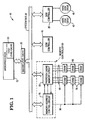
- FIG. 1 is a block diagram of a computer system employing a main memory prefetch cache in accordance with the present invention.
- Figure 2 is a block diagram of the memory address control circuit portion of the memory controller in the computer system of Figure 1.
- FIG. 3 is a block diagram of the prefetch cache memory circuit portion of the computer system of Figure 1.
- Figure 4 is a detailed schematic diagram of one of the 16 tag registers employed in the memory address control circuit portion of Figure 2.
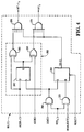
- FIG. 5 is a detailed schematic diagram of one of the 16 Least Recently Used (LRU) counters employed in the memory address control circuit portion of Figure 2.
- LRU Least Recently Used
- Figure 6 is a flowchart which shows an overview of the step by step operation of a method of fetching instructions in accordance with the invention.
- System 10 includes a microprocessor 15 which, in one embodiment, includes a cache 20 integrated in the chip on which microprocessor 15 is fabricated.
- a cache 20 integrated in the chip on which microprocessor 15 is fabricated.
- an INTEL 80486 which includes an 8K internal cache is suitable for use as microprocessor 15.
- cache 20 is referred to as a "first level" cache.
- computer system 10 includes another cache memory 25 which is externally coupled to microprocessor 15 as shown.
- Cache memory 25 is a "second level" cache memory that works in conjunction with first level cache memory 20 to supplement cache memory 20.
- First level cache memory 20 is relatively small in comparison with the size of second level cache memory 25.
- Second level cache memory 25 is'an external cache which exhibits a size typically within the range of 32K - 512K bytes or larger of high speed, static read only memory (SRAM).
- SRAM static read only memory
- the invention can be also be practiced with a microprocessor 15 which has only an internal cache without an external, second level cache such as cache memory 25.
- the invention can be practiced with a microprocessor which does not have an integrated cache such as cache 20, provided an external processor cache memory such as cache memory 25 is used in conjunction with the microprocessor.
- first level cache memory 20 and second level cache memory 25 are both "processor" cache memories in that they are both local to processor 15.
- Second level cache memory 25 is coupled to a system bus 30 to enable microprocessor 15 to communicate with other components of computer system 10.
- a disk controller 35 is coupled to system bus 30 to interface one or more hard disk drives 40 to computer system 10.
- a communication controller card 45 is coupled to system bus 30 to provide system 10 with serial and parallel ports.
- a memory controller 50 is coupled to system bus 30 as shown.
- Memory controller 50 includes a prefetch cache memory circuit 55 which is coupled to a main memory 60 via data lines 65.
- Main memory 60 includes a plurality of memory elements 70, for example dynamic random access memory (DRAM) surface in-line memory modules (SIMMs) or the like.
- DRAM dynamic random access memory
- SIMMs surface in-line memory modules
- Memory controller 50 also includes a memory address control circuit 75 for controlling requests for access to main memory 60 from microprocessor 15.
- Memory address control circuit 75 is coupled to system bus 30 and prefetch cache memory circuit 55.
- Memory address control circuit 75 is also coupled to main memory 60 by address, row address strobe (RAS), column address strobe (CAS), read enable and write enable lines which are shown collectively as lines 80 in Figure 1.
- RAS row address strobe
- CAS column address strobe
- read enable and write enable lines which are shown collectively as lines 80 in Figure 1.
- FIG. 2 shows a more detailed block diagram of the memory address control circuit 75 portion of memory controller 50.
- Memory address control circuit 75 includes an address tag register and comparator block 85 having 16 sets of address tag registers and comparators, This constitutes one address tag register and comparator combination per each of the 16 registers in prefetch cache 198 (see Figure 3), as discussed later.
- Memory address control circuit 75 is coupled to system bus 30 as shown to receive address requests therefrom.
- the tag registers in register/comparator block 85 are used to store the addresses of the instructions which are currently stored in prefetch cache memory circuit 55.
- the comparators in register/comparator block 85 are used to determine if there is a match (a hit) between a requested address and an address currently stored in prefetch memory 55.
- Register/comparator block 85 includes two groups of 16 outputs, namely HIT 0 through HIT 15 and HIT+1 0 through HIT+1 15 . When a request is made to memory controller 50 for an instruction at a particular address, one of outputs HIT 0 through HIT 15 corresponding to the register location of that: address in the prefetch cache goes true if there is a cache hit. The operation and configuration of register/comparator block 85 will be discussed in more detail later.
- Memory address control circuit 75 further includes least recently used (LRU) counter block 90 which contains a set of 16 LRU counters.
- the LRU counters act to assure that the most often used instructions are contained in prefetch cache memory 55. In other words, the least recently used instruction is selected for replacement when prefetch cache 55 is full.
- a respective LRU counter is thus provided for each of the address tag registers in address tag register/comparator block 85. More particularly, the first LRU counter in LRU counter block 90 corresponds to and is coupled to the first address tag register/comparator in block 85 via hit output line HIT0, and the second LRU counter in LRU counter block 90 corresponds to and is coupled to the second address tag register/comparator in block 85 via hit output line HIT 1 , and so forth.
- LRU counter block 90 includes 16 REGx outputs, designated REG 0 , REG 1 , .. REG 15 , which are coupled to a 16 to 4 encoder 95 and back to address tag register/comparator block 85. Encoder 95 converts the 1 of 16 lines into a 4 bit REG POINTER value signal at its output. LRU counter block 90 also includes 16 CNT x outputs, designated CNT 0 CNT 1 , ... CNT 15 , which are coupled to a 16 to 1 multiplexer 100 such that a HIT COUNT signal is generated at the output thereof. The HIT COUNT signal is fed back to LRU counter block 90. A /HIT signal is supplied to multiplexer 100. The nature and function of the REG x ,CNT x , HIT COUNT and /HIT signals will be discussed in a later example.
- Memory address control circuit 75 also incorporates an address+1 adder 105 which is coupled to system bus 30. Address+1 adder 105 takes an address request received from system bus 30 and advances that address to the next sequential address in main memory. Adder 105 includes an ADDRESS+1 output which is coupled to register/comparator block 85 and to a multiplexer 110 as shown in Figure 2. System bus 30 is also coupled to an input of multiplexer 110. The output of multiplexer 110 is coupled to main memory 70 such that either the requested current address or the current address plus 1 can be passed to and accessed from main memory 70.
- FIG. 3 is a block diagram of prefetch cache memory circuit 55 including read path of main memory controller 50.
- Prefetch circuit 55 includes a prefetch cache memory 198 having 16 sets of cache registers designated as register sets 200, 201, ... 215.
- Prefetch cache memory 198 is coupled to main memory 60 such that memory 198 can store instructions (code and data) retrieved from main memory 60.
- the output of each of cache register sets 200-215 is coupled to a respective input of a 16 to 1 multiplexer 220.
- the REG POINTER output of memory address control circuit 50 of Figure 2 is coupled to multiplexer 220 as shown in FIG. 3 to select a particular cache register from which data is to be obtained.
- Main memory 60 is also coupled via an input register 225 to an input of a 2 to 1 multiplexer 230.
- the output of 16 to 1 multiplexer 220 is coupled to another input of 2 to 1 multiplexer 230 as shown in Figure 3.
- Multiplexer 230 includes an output which is coupled via an output register 235 to a 4 to 1 multiplexer 240.
- Multiplexer 230 also includes a /HIT input to select whether data for the processor comes from main memory or from the data cache.
- the output of 4 to 1 multiplexer 240 is coupled to system bus 30 such that lines or instructions (code and data) at requested addresses can be provided to microprocessor 15 at the bus width needed by microprocessor 15.
- a detailed schematic diagram of one of the 16 tag registers 85 used in memory address control circuit 75 is shown in Figure 4 as tag register circuit 85(0).
- the sample tag register 85(0) includes ADDR+1, LOAD, ADDR, REG x , INVALIDATE and RESET inputs.
- the function of the ADDR signal received from system bus 30 is to communicate to memory controller 50 the particular address corresponding to an instruction which microprocessor 15 wants to retrieve from main memory 60.
- the ADDR+1 input of tag register 85(0) is coupled to the ADDR+1 output of ADDRESS+1 adder 105.
- ADDR is the address which microprocessor is currently attempting to retrieve from main memory 60
- ADDR+1 is the next sequential address in main memory 60 following address ADDR.
- ADDR+1 is the address of the next sequential line or instruction following ADDR.
- the ADDR+1 comparator is needed to prevent loading a second ADDR+1 line into the cache if a first ADDR+1 line is already present therein.
- the ADDR+1 input of tag register 85(0) is coupled to the D input of a D flip flop 245 as shown in Figure 4.
- the LOAD input of tag register 85(0) is coupled to one input of a two input AND gate 250, the remaining input of which is coupled to the REG x input and one input of another two input AND gate 255.
- the derivation of the REG x signal on the REG x input will be discussed later.
- the INVALIDATE line is coupled to the remaining input of AND gate 255.
- the INVALIDATE pulse is used to clear the "VALID" bit of a cache line if processor 15 is writing to main memory and the main memory location was previously stored in the cache.
- the output of AND gate 250 is coupled to the clock input of D flip flop 245 and to the S input of an RS flip flop 260.
- the output of AND gate 255 is coupled to the R input of RS flip flop 260.
- the output of RS flip flop 260 is designated as the VALID output and is coupled to one input of multi-input AND gate 265 and to one input of multi-input AND gate 270.
- the ADDR+1 input of tag register 85(0) is coupled to one input of two input EX OR gate 285, the remaining input of which is coupled to the Q output of D flip flop 245 and to one input of a two input EX OR gate 290.
- the remaining input of EX OR gate 290 is coupled to the ADDR input of tag register 85(0).
- Flip flop 245 and EX OR gates 285 and 290 form a block 292 which is repeated in tag address register/comparator block 85(0) as many times as there are address bits in main memory 60.
- block 292 is repeated 32 times, namely, once per each bit of the address.
- the outputs of EX OR gates 285 and 290 in such repeated blocks 292 are coupled to respective inputs on AND gates 265 and 270.
- AND gates 265 and 270 are illustrated with multiple inputs in Figure 4 although to conserve space the specific connection of each of such multiple inputs is not shown.
- a HIT x signal is generated at the output of AND gate 270 and a HIT+1 x signal is generated at the output of AND gate 265. If the HIT x signal is true, this indicates that a match to the current processor access request can be supplied from the prefetch cache at register location x therein. It will be recalled that the 16 data registers of prefetch cache 198 are labelled 200-215 which corresponds to values of x from 0-15. In other words, if HIT 3 goes true, there is a hit in prefetch register 203, and so forth. If the HIT x +1 signal is true, then the next sequential memory line is already in the prefetch cache and it is not necessary to do a memory prefetch for this line.
- LRU counter 90(0) includes inputs HIT COUNT, /HIT, PRESET, PRESET VALUE x , LOAD and HIT x to which HIT COUNT, /HIT, PRESET, PRESET VALUE x , LOAD and HIT x signals are respectively provided .
- the LOAD input of LRU counter 90(0) is coupled to one input of a two input AND gate 300 and to one input of a two input NAND gate 305.
- the /HIT input of LRU counter 90(0) is coupled to one input of a two input AND gate 310, the output of which is coupled to one input of a two input OR gate 315.
- the remaining input of OR gate 315 is coupled to the HIT x input.
- the output of OR gate 315 is coupled to the remaining input of NAND gate 305 and forms the REG x output of LRU counter 90(0) at which the REG x output signal is generated.
- the output of AND gate 300 is coupled to the INC input of a counter 320.
- the output of NAND gate 305 is coupled to an inverting clear input CLR of counter 320.
- the PRESET and PRESET VALUE x signals are provided to counter 320 as shown in Figure 5.
- the PRESET VALUE x signal provides 16 different initial count values to the 16 respective LRU counters 320 at a time indicated by the PRESET command signal.
- the output of counter 320 is designated CNT x and is coupled to the B input of a comparator'325 having inputs A and B.
- the HIT COUNT input value is provided to the remaining A input of comparator 325 as shown.
- the B ⁇ A output of comparator 325 is coupled to the remaining input of AND gate 300.
- LRU counter block 90 operates in the following manner.
- the LRU mechanism employed in counter block 90 consists of a 4 bit LRU counter 320 associated with each of the 16 cache tag entry/lines.
- counter 320 has 16 possible count values, namely 0,1,2,...15. If a cache hit on line x occurs, then line x's counter will be cleared and all counters for lines having a count value lower than x's previous count value are incremented by 1 when the LOAD pulse occurs. If a cache miss occurs, then the tag register and cache line corresponding to the counter that has a count value 1111 (or decimal 15) are cleared and used for the new tag/data and all other counters are incremented by 1. Counters 320 do not overflow, but rather are all initialized to an incrementing value from 0000 to 1111.
- Main memory prefetch cache 55 may be viewed as assisting a processing unit 15 which already has a processor cache such as internal cache 20 and/or external cache 25.
- microprocessor 15 When microprocessor 15 attempts to access a current line (a first instruction which is either code or data) it sees that the contents of all caches are invalid and therefore an access directly to main memory 60 (DRAM) is made.
- Memory controller 50 locates the current line in main memory 60 and sends the current line to output register 235 where it is later transferred to microprocessor 15 for processing.
- the current line is stored in one or both of internal cache 20 and external cache 25, and the current line+1 is prefetched and stored in prefetch cache 55.
- the current line+1 is defined as the instruction stored at the next sequential instruction address in main memory 60 after the current instruction. More particularly, the current line+1 is accessed and stored in prefetch memory simultaneously with the transfer of the current line to the processor so as not to contribute to system overhead.
- microprocessor 15 sends a request for the new current line to memory controller 50, such request consisting of the address of the new current line.
- Memory controller 50 starts a main memory cycle (DRAM cycle) and simultaneously looks to see if the requested new current line is stored in prefetch cache memory 55. If the new current line is stored in prefetch cache 55 as per a cache hit, it is accessed, sent to microprocessor 15 for processing and the main memory cycle (DRAM cycle) is modified to retrieve the new current line+1. Once retrieved, the new current line+1 is stored in prefetch cache 55.
- DRAM cycle main memory cycle
- prefetch mechanism employed in prefetch cache 55 stays one step ahead of line requests to memory controller 50 without contributing any extra system bus cycle overhead.
- the new current line is retrieved from prefetch cache 55 and temporarily stored in output register 235 for later transfer to microprocessor 15.
- the current line+1 comes in from main memory, it is stored back into the same location in the prefetch cache that the current line was in. Because of this, a small set of cache registers can track multiple processing threads.
- the microprocessor's line request to memory controller 50 is the result of a branch instruction in the program which is being executed, then the lookup in prefetch cache memory 55 will fail and a cache miss occurs.
- the main memory cycle (DRAM cycle) is not modified, but rather continues. In other words, the address sought in the memory cycle which results from the memory request is not changed and the memory cycle proceeds forward.
- the instruction (code or data) at the requested address in main memory 60 is obtained and stored in output register 235 for later transfer to microprocessor 15.
- a DRAM page mode access continues and retrieves the next line after the new current line (ie. the new current line+1).
- the new current line+1 is then stored in prefetch cache 55 so that prefetch cache 55 is prepared if microprocessor 15 continues executing instructions along the same sequential instruction path. This fetch from main memory 60 is at page mode access speed and is faster than a normal main memory access.
- the cache miss scenario described immediately above is in contrast to the cache hit scenario described earlier wherein the new current line corresponding to the requested address was found to be stored in prefetch cache 55. It will be recalled that in the event of such a cache hit, the address sought from main memory in the main memory cycle was modified from the address of the new current line to the address of the new current line+1. The new current line+1 retrieved from main memory is then used to overwrite the new current line which was found to be stored in the prefetch cache.
- LRU counters, encoder 95 and multiplexer 100 The purpose of LRU counters, encoder 95 and multiplexer 100 is to select the particular line in prefetch cache memory 55 which has been least recently used. More particularly, in a cache miss situation, this least recently used line is replaced with new data from the main memory when the cache becomes full.
- REG POINTER signal depicted in Figure 2 at the output of encoder 95.
- the main purpose of the REG POINTER signal is to select from which of prefetch data cache registers 198 that data is going to be obtained. It is also noted that in Figure 2, the REG POINTER signal is fed back to multiplexer 100 to select which of the 16 CNT x count values provided to multiplexer 100 gets fed back to LRU counters 90 as HIT COUNT.
- a respective LRU counter 320 is provided for each of the 16 lines stored in the 16 prefetch cache registers 200-215 in prefetch memory 55.
- Each of the LRU counters 320 in LRU counter block 90 maintains a count number, CNT x , which indicates how recently the corresponding line in cache 55 has been accessed or used, wherein x varies from 0 through 15 according to which of the 16 counters or corresponding lines in the prefetch cache memory is being referenced. If in a cache hit situation a particular LRU counter 320 contains a count of 0, then the corresponding register in prefetch memory register block 198 has just had a line of data written to it.
- This action causes the count value in that LRU counter 320 to be reset to 0 indicating that the corresponding prefetch data register has been most recently used. If in the next memory cycle, no data is needed from that same line or location in that particular register, then the corresponding LRU counter is incremented from a value of 0 to a value of 1. Selected ones of the remaining 15 LRU counters are also incremented by 1 as described later. When the count CNT x of a particular LRU counter reaches 15, then the data in the prefetch memory location corresponding to that LRU counter is selected for replacement should a cache miss occur.
- a respective address tag register/comparator 85 block is provided for each of prefetch cache data registers 200-215. That is, tag register circuit 85(0) is provided for cache register 200, tag register circuit 85(1) is provided for cache register 201 and tag register 85(15) is provided for cache register 215.
- the memory controller first looks to the prefetch cache to see if the requested instruction is contained in a line stored therein. Block 85 checks to see if there is a cache hit in prefetch cache 55.
- block 85 checks to see if any of the 16 prefetch cache registers 200-215 in prefetch cache 55 contain the requested line, the address of which is provided to each of the 16 ADDR inputs of the 16 blocks 85 (see Figure 4). This is accomplished by checking the address of the requested line with the addresses stored in the 16 tag registers within block 85. If there is a match, then there is a cache hit. Blocks 85 also conduct a check to determine if the ADDR+1 line is already stored in prefetch cache memory. This is done to make sure that the same line is not stored in the prefetch cache at two different locations.
- the true HIT 3 value is fed to OR gate 315 as seen in the LRU counter of Figure 5 and appears at the output thereof as REG x which in this example is REG 3 .
- REG 3 is true while all other REG x values other than REG 3 are false.
- the REG 3 value is provided to encoder 95 ( Figure 2) which supplies a value of 3 at its 4 bit REG POINTER output so that the line stored in prefetch cache data register 203 ( Figure 3) of prefetch cache 198 can be selected. (Note the numerical correspondence of the REG POINTER value of 3 and the prefetch data register number 203 which it selects. A REG POINTER value of 4 would be used to select the contents of prefetch register 204, and so forth.)
- CNT 3 is assumed to have a value of 8
- a HIT COUNT value of 8 is fed back to LRU counters 90.
- each of the 16 LRU counters is associated with a respective corresponding tag address register and prefetch cache data register.
- the CNT values in the LRU counter circuits 90 are changed (incremented or cleared) according to the recentness of use of the corresponding data lines in the prefetch cache data registers.
- the LRU counter 90(x) corresponding to the data line for which the hit occurred is set back to 0 indicating that such data line is most recently used. Also when such a cache hit occurs, the current line requested by the microprocessor is moved from the appropriate prefetch cache data register 200 to output register or buffer 235 for subsequent transmittal to the microprocessor. The current line is overwritten with the next line from main memory and the tag register 85(x) corresponding to the overwritten line is updated with the new address information of the next line for prefetch cache content tracking purposes.
- LRU counter circuit 90 Upon initialization of computer system 10, a different unique CNT x value from 0 to 15 is stored in the respective LRU counters 320 of counter circuits 90(0), 90(1),... 90(15).
- LRU counter circuit 90(3) which is identical to LRU counter circuit 90(0) is now considered. It was earlier noted that LRU counter circuit 90(3) is the LRU counter corresponding to the prefetch cache register 203 for which a cache hit was observed. It was arbitrarily assumed for purposes of example that the CNT 3 value in counter 90(3) is 8. Thus a CNT 3 value of 8 is provided to the B input of comparator 325. A HIT COUNT value of 8 is also provided to the A input of comparator 325 in this case.
- the LOAD pulse is issued.
- the values stored in the LRU counters 320 change in the manner now described.
- the LOAD pulse drops down and feeds through NAND gate 305 to cause LRU counter 320 to be cleared or reset to a count value of 0. That is, the CNT 3 count in LRU counter 320 of counter circuit 90(3) goes from a value of 8 to a value of 0. This indicates that a cache hit has occurred and that the contents of the corresponding prefetch cache data register 203 are "most recently used" or fresh.
- LRU counter 320 in remaining counter circuit 90(0) is now considered in the present case where the cache hit occurred in prefetch data register 203 (to which counter circuit 90(3) corresponds). Since the cache hit occurred in prefetch data register 203 and not in register 200 (which corresponds to counter circuit 90(0)), it is observed that HIT(0) is false, but HIT COUNT is still 8. It is assumed that the count value CNT 0 stored in LRU counter 320 in counter circuit 90(0) is a 5, an arbitrary value selected for purposes of this example.
- the case of a cache hit is first considered.
- the current line requested by the microprocessor is contained in prefetch cache 55.
- the current line is retrieved and sent to output register 235 for transfer to the microprocessor.
- the next line subsequent to the current line is retrieved from main memory and is used to overwrite the current line in the prefetch cache.
- the particular LRU counter 90(0)-90(15) corresponding to that prefetch data register is cleared (reset to zero) and all remaining LRU counters 90 having a count value less than the count value in that particular counter are incremented by one.
- the count value in the remaining LRU counters 90 is unchanged when there is a cache hit.
- the particular tag register 85 and particular prefetch cache register 200-215 corresponding to the LRU counter 90 whose count value equals the maximum count of 1111 (decimal 15) are selected.
- this particular tag register and prefetch cache register are then used to store the new tag address and new data line (current line) from main memory, respectively, and this LRU count is cleared from a count of 15 to zero. All remaining counters 90 are incremented by 1 in the case of a cache miss.
- Computer system is 10 initialized at block 400 and starts executing instructions at block 405 at which microprocessor 15 requests a current line. Since computer system 10 was just initialized, cache misses occur in the internal cache 20, the external cache 25 and the main memory prefetch cache 55. In that event, memory controller 50 locates the current line in main memory 60 as a result of a main memory cycle as per block 410. The current line is sent from main memory 60 to output register 235 at block 415 and is later transmitted to microprocessor 15 as per block 420. Simultaneously with block 420 wherein the current line is sent to microprocessor 15, the current line+1 is prefetched from main memory 60 and is stored in prefetch cache memory 55 as per block 425.
- Microprocessor 15 continues executing its program and then requests a new current line as per block 430.
- memory controller 50 starts a main memory cycle at block 435 to retrieve the new current line.
- Memory controller 50 determines if the new current line is in prefetch cache 55 as per block 440. This determination is made at the beginning of the main memory cycle initiate at block 435.
- the new current line in the cache is accessed and stored in output register 235 as per block 445.
- the new current line is then sent from output register 235 to microprocessor 15 as per block 450.
- the main memory cycle commenced at block 435 is the modified at block 455 to retrieve the new current line+1 from main memory 60 instead of the new current line. This retrieval of the new current line+1 in block 455 occurs simultaneously with transmission of the new current line to microprocessor 15 at block 450.
- the new current line+1 which was retrieved from main memory 60 is then stored in prefetch cache 55 by overwriting the current line with the new current line+1 as per block 460.
- the particular LRU counter 90(x) which corresponds to the particular prefetch cache data register in which the hit occurred is then cleared or reset to zero to indicate that this particular prefetch data register's contents are the most recently used.
- This particular prefetch data register's contents are the most recently used because the new current line+1 has just overwritten the current line which previously occupied this location.
- the LRU counters which have a count value less than HIT COUNT are incremented by one as per block 462. The count value in the remaining LRU counters is left unchanged as per block 463.
- microprocessor 15 executes the next instruction in the program and requests another new current line from memory controller 55.
- the main memory cycle initiated at block 435 is continued at block 465 to retrieve that new current line from main memory 60.
- the new current line is stored in output register 235 as per block 470 for later transfer to microprocessor 15 as per block 475.
- the main memory page mode access continues so as to retrieve the new current line+1 at block 480 simultaneously with the new current line being sent to microprocessor 15 at block 475.
- the new current line+1 is then stored in prefetch cache 55 at the register location corresponding to the particular LRU counter circuit 90(x) exhibiting a maximum count value as per block 485.
- the least frequently used line was stored in that register location and is purged by this action.
- the remaining LRU counter circuits 90 are then incremented by one as per block 490.
- microprocessor 15 executes the next instruction in the program and requests yet another new current line from memory controller 55.
- a method of accessing the main memory of a computer which includes the step of providing a main memory prefetch cache situated in a memory controller and coupled to the main memory.
- the method includes the step of initiating a main memory cycle to retrieve a current line from the main memory.
- the method further includes the step of determining, by the memory controller, if the current line is stored in the prefetch cache. If the current line is determined to be stored in the prefetch cache, then the method includes retrieving the current line from the prefetch cache and providing the current line to the processor, and retrieving the next line from the main memory and overwriting the current line in the prefetch cache with the next line. If however the current line is determined not to be stored in the prefetch cache, then the method includes retrieving the current line from the main memory and providing the current line to the processor, and retrieving the next line from the main memory and storing the next line in the prefetch cache.
- the method further includes the steps of providing a respective least recently used (LRU) counter corresponding to each of the registers in the prefetch cache and initializing each of the LRU counters at a unique predetermined count value between 0 and X inclusive. If in the determining step the current line is determined to be stored in the prefetch cache as per a cache hit, then the method includes clearing the count value stored in the particular LRU counter corresponding to the register in the prefetch cache for which the cache hit occurred and further includes incrementing the LRU counters whose count values are less than the count value of the particular LRU counter prior to the clearing step.
- LRU least recently used
- the method includes storing the next line in the register in the prefetch cache corresponding to the LRU counter having a maximum count X, and further includes incrementing the remaining counters.
- the foregoing has described a computer system including a cache memory which enhances effective microprocessor execution speed with respect to branch and code return instructions.
- the disclosed computer system employs a prefetch cache memory which is integrated in the memory controller of the main memory to enhance performance significantly.
- the computer system of the present invention includes a main memory prefetch cache which achieves prefetching without contributing extra system overhead.
- the disclosed main memory prefetch cache can also enhance the performance of multiprocessor computer systems.
Landscapes
- Engineering & Computer Science (AREA)
- Theoretical Computer Science (AREA)
- Software Systems (AREA)
- Physics & Mathematics (AREA)
- General Engineering & Computer Science (AREA)
- General Physics & Mathematics (AREA)
- Memory System Of A Hierarchy Structure (AREA)
Claims (10)
- Système informatique (10) comprenant :caractérisé en ce que le système informatique (10) comprend en outre x compteurs (90) Utilisées le Moins Récemment (LRU), chaque compteur LRU (90) correspondant à l'un respectif des registres d'antémémoire de pré-extraction (198), chaque compteur (90) contenant une valeur de comptage indiquant le temps s'étant écoulé depuis que les contenus du registre d'antémémoire de pré-extraction (198) correspondant ont été utilisés, et en ce queun processeur (15) ;une antémémoire de processeur (20) reliée au processeur (15) ;un contrôleur de mémoire (50) relié au processeur (15) ; etune mémoire centrale (60) reliée au contrôleur de mémoire (50);le contrôleur de mémoire (50) comportant :une antémémoire de pré-extraction de mémoire centrale (55) comprenant x registres d'antémémoire de pré-extraction (198) destinés à stocker des informations pré-extraites de la mémoire centrale (60), x étant un entier fini, etun moyen de commande (75) relié à l'antémémoire de pré-extraction pour déterminer si un accès réussi s'est produit dans l'antémémoire, dans lequel une ligne courante demandée par le processeur (15) est stockée dans l'un des registres d'antémémoire de pré-extraction (198) et, si tel est le cas, pour extraire alors la ligne courante du registre d'antémémoire de pré-extraction (198) afin qu'elle soit utilisée par le processeur (15) et remplacer la ligne courante contenue dans le registre d'antémémoire de pré-extraction (198) par une ligne suivante provenant de la mémoire centrale (60) ou, dans le cas contraire, lorsque aucun des registres d'antémémoire de pré-extraction (198) ne contient la ligne courante demandée par le processeur (15), ce qui représente un accès non réussi dans l'antémémoire, pour extraire alors la ligne courante de la mémoire centrale (60) afin qu'elle soit utilisée par le processeur (15), extraire la ligne suivante de la mémoire centrale (60) et stocker cette ligne suivante dans l'antémémoire de pré-extraction (55) afin que la ligne suivante soit transférée à l'antémémoire de pré-extraction (55) avant une demande concernant cette ligne suivante provenant du processeur (15) ;
le moyen de commande (75) est apte à déterminer, sur la base des valeurs de comptage, la ligne utilisée le moins récemment dans les registres d'antémémoire de pré-extraction (198), qui doit être remplacée par la ligne suivante, afin de permettre ainsi à l'antémémoire de pré-extraction (55) de fonctionner en tant qu'antémémoire du type à mémoire entièrement associative. - Système informatique (10) suivant la revendication 1, comprenant en outre un moyen de remise à zéro (100) pour remettre à zéro une valeur de comptage désignée "HIT COUNT" dans un compteur LRU (90) correspondant à un registre d'antémémoire de pré-extraction (198) contenant une ligne d'informations demandée dans laquelle un accès réussi dans l'antémémoire est considéré comme s'étant produit.
- Système informatique (10) suivant la revendication 2, comprenant en outre un premier moyen d'incrémentation (85), relié aux compteurs LRU (90), pour incrémenter tous les compteurs LRU (90) dont la valeur de comptage est inférieure à la valeur "HIT COUNT" lorsqu'il se produit un accès réussi dans l'antémémoire, la valeur de comptage des autres compteurs LRU (90) restant inchangée lorsqu'il se produit un accès réussi dans l'antémémoire.
- Système informatique (10) suivant la revendication 3, comprenant en outre un moyen de vidage, relié à l'antémémoire de pré-extraction (20), pour vider l'antémémoire de pré-extraction (20) de la ligne utilisée le moins récemment lorsqu'il se produit un accès non réussi dans l'antémémoire par écriture de la ligne suivante dans le registre d'antémémoire (198) particulier correspondant au compteur LRU (90) présentant une valeur de comptage maximale.
- Système informatique (10) suivant la revendication 4, comprenant en outre un second moyen d'incrémentation, relié aux compteurs LRU (90), pour incrémenter les compteurs LRU (90) autres que le compteur LRU (90) correspondant au registre d'antémémoire particulier (198) dans lequel la ligne suivante est écrite lorsqu'il se produit un accès non réussi dans l'antémémoire.
- Système informatique (10) suivant l'une quelconque des revendications précédentes, caractérisé en ce que l'antémémoire de processeur (20) comprend une antémémoire de processeur interne intégrée au processeur (15).
- Système informatique (10) suivant l'une quelconque des revendications précédentes, caractérisé en ce que l'antémémoire de processeur (20) comprend une antémémoire de processeur externe reliée extérieurement au processeur (15).
- Procédé d'accès à une mémoire dans un système informatique (10) comportant un processeur (15), une antémémoire de processeur (20) reliée au processeur (15), un contrôleur de mémoire (50) relié au processeur (15), une mémoire centrale (60) reliée au contrôleur de mémoire, une antémémoire de pré-extraction de mémoire centrale (55) comprenant x registres d'antémémoire de pré-extraction (198) destinés à stocker des informations pré-extraites de la mémoire centrale (60), x étant un entier fini ; et un moyen de commande (75) relié à l'antémémoire de pré-extraction (55), le procédé consistant à :
déclencher un cycle de la mémoire centrale pour extraire une première ligne d'informations de la mémoire centrale (60) ; déterminer à l'aide du moyen de commande (75) si la première ligne d'informations est stockée dans l'un des registres d'antémémoire de pré-extraction (198) et, si tel est le cas, extraire alors la première ligne d'informations du registre d'antémémoire de pré-extraction (198) et fournir cette première ligne d'informations au processeur (15), extraire la ligne d'informations suivante de la mémoire centrale (60) et remplacer la première ligne d'informations dans le registre d'antémémoire de pré-extraction (198) par la ligne d'informations suivante provenant de la mémoire centrale (60) et, s'il est déterminé que cette première ligne d'informations n'est pas stockée dans l'un quelconque des registres d'antémémoire de pré-extraction (198), extraire alors cette première ligne d'informations de la mémoire centrale (60) et fournir cette première ligne d'informations au processeur (15), et extraire cette ligne d'informations suivante de la mémoire centrale (60) et stocker la ligne d'informations suivante dans l'antémémoire de pré-extraction (55) avant une demande concernant la ligne suivante provenant du processeur (15), caractérisé en ce que le procédé consiste en outre à :
déterminer, par utilisation de x compteurs (90) d'Utilisation la Moins Récente (LRU), qui correspondent chacun à l'un des registres d'antémémoire de pré-extraction (198) et qui contiennent chacun une valeur de comptage indiquant ie temps depuis lequel les contenus du registre d'antémémoire de pré-extraction (198) correspondant ont été utilisés, la ligne utilisée le moins récemment dans les registres d'antémémoire de pré-extraction (198) sur la base des valeurs de comptage, si cette première ligne d'informations ne se trouve pas dans les registres d'antémémoire de pré-extraction (198), et s'il est considéré qu'un accès non réussi dans l'antémémoire s'est produit ; extraire cette première ligne d'informations de la mémoire centrale (60) ; et stocker la ligne d'informations suivante provenant de la mémoire centrale (60), après la première ligne d'informations, dans le registre d'antémémoire de pré-extraction (198) particulier occupé par cette ligne d'informations utilisée le moins récemment, afin de permettre ainsi la mise en oeuvre du procédé d'une manière convenant pour une antémémoire du type mémoire entièrement associative. - Procédé suivant la revendication 8, caractérisé par le fait de modifier le cycle de la mémoire centrale pour extraire la ligne d'informations suivante de la mémoire centrale (60) plutôt que la première ligne d'informations lorsque, lors de l'étape de détermination, il est déterminé que la première ligne d'informations est stockée dans l'antémémoire de pré-extraction (55).
- Procédé suivant la revendication 8 ou 9, consistant en outre à :
utiliser un compteur (90) d'utilisation la moins récente (LRU) respectif correspondant à chacun des x registres (198) dans l'antémémoire de pré-extraction (55) ; initialiser chacun des compteurs LRU (90) à une valeur de comptage unique déterminée à l'avance comprise entre 0 et X inclus ; si, lors de l'étape de détermination, il est déterminé que la première ligne d'informations est stockée dans l'antémémoire de pré-extraction (55) lors d'un accès réussi dans l'antémémoire, remettre alors à zéro la valeur de comptage stockée dans le compteur LRU (90) particulier correspondant au registre (198) dans l'antémémoire de pré-extraction (55) pour laquelle cet accès réussi s'est produit dans l'antémémoire ; incrémenter les compteurs LRU (90) dont les valeurs de comptage sont inférieures à la valeur de comptage du compteur LRU particulier (90) avant l'étape de remise à zéro ; si, lors de l'étape de détermination, il est déterminé que la première ligne d'informations n'est pas stockée dans l'antémémoire de pré-extraction (55) lors d'un accès manqué dans l'antémémoire, stocker alors la ligne d'informations suivante dans le registre (198) de l'antémémoire de pré-extraction (55) correspondant au compteur LRU (90) ayant un comptage X maximum, et incrémenter les autres compteurs LRU (90).
Applications Claiming Priority (2)
| Application Number | Priority Date | Filing Date | Title |
|---|---|---|---|
| US996533 | 1992-12-24 | ||
| US07/996,533 US5566324A (en) | 1992-12-24 | 1992-12-24 | Computer apparatus including a main memory prefetch cache and method of operation thereof |
Publications (2)
| Publication Number | Publication Date |
|---|---|
| EP0604139A1 EP0604139A1 (fr) | 1994-06-29 |
| EP0604139B1 true EP0604139B1 (fr) | 2001-10-31 |
Family
ID=25543018
Family Applications (1)
| Application Number | Title | Priority Date | Filing Date |
|---|---|---|---|
| EP93310254A Expired - Lifetime EP0604139B1 (fr) | 1992-12-24 | 1993-12-17 | Système d'ordinateur avec une antémémoire de préextraction |
Country Status (4)
| Country | Link |
|---|---|
| US (1) | US5566324A (fr) |
| EP (1) | EP0604139B1 (fr) |
| JP (1) | JPH07129471A (fr) |
| DE (1) | DE69331039T2 (fr) |
Families Citing this family (46)
| Publication number | Priority date | Publication date | Assignee | Title |
|---|---|---|---|---|
| EP0613087B1 (fr) * | 1993-02-24 | 2002-11-20 | Matsushita Electric Industrial Co., Ltd. | Dispositif et procédé d'accés rapide de lecture à mémoire |
| TW228580B (en) * | 1993-10-01 | 1994-08-21 | Ibm | Information processing system and method of operation |
| CA2118278C (fr) * | 1993-12-21 | 1999-09-07 | J. David Garland | Systeme multimedia |
| US5832231A (en) * | 1995-01-13 | 1998-11-03 | U S West, Inc. | Method and system for preloading interactive multimedia applications |
| US5689255A (en) * | 1995-08-22 | 1997-11-18 | Hewlett-Packard Company | Method and apparatus for compressing and decompressing image data |
| US5758119A (en) * | 1995-08-23 | 1998-05-26 | International Business Machines Corp. | System and method for indicating that a processor has prefetched data into a primary cache and not into a secondary cache |
| US5740399A (en) * | 1995-08-23 | 1998-04-14 | International Business Machines Corporation | Modified L1/L2 cache inclusion for aggressive prefetch |
| US5737565A (en) * | 1995-08-24 | 1998-04-07 | International Business Machines Corporation | System and method for diallocating stream from a stream buffer |
| US5664147A (en) * | 1995-08-24 | 1997-09-02 | International Business Machines Corp. | System and method that progressively prefetches additional lines to a distributed stream buffer as the sequentiality of the memory accessing is demonstrated |
| US5860138A (en) * | 1995-10-02 | 1999-01-12 | International Business Machines Corporation | Processor with compiler-allocated, variable length intermediate storage |
| JP3886189B2 (ja) * | 1995-12-18 | 2007-02-28 | テキサス インスツルメンツ インコーポレイテツド | バースト可でキャッシュ不可のメモリアクセスを支援するマイクロプロセッサ装置 |
| US5778422A (en) * | 1996-04-04 | 1998-07-07 | International Business Machines Corporation | Data processing system memory controller that selectively caches data associated with write requests |
| US5983313A (en) * | 1996-04-10 | 1999-11-09 | Ramtron International Corporation | EDRAM having a dynamically-sized cache memory and associated method |
| US5724613A (en) * | 1996-05-06 | 1998-03-03 | Vlsi Technology, Inc. | System and method for automatically enabling and disabling a prefetching capability |
| US5867731A (en) * | 1996-08-12 | 1999-02-02 | Unisys Corporation | System for data transfer across asynchronous interface |
| US6055600A (en) * | 1996-12-19 | 2000-04-25 | International Business Machines Corporation | Method and apparatus for detecting the presence and identification of level two cache modules |
| US6490658B1 (en) * | 1997-06-23 | 2002-12-03 | Sun Microsystems, Inc. | Data prefetch technique using prefetch cache, micro-TLB, and history file |
| US6073225A (en) * | 1997-06-24 | 2000-06-06 | Intel Corporation | Method and apparatus for monitoring bus transactions based on cycle type and memory address range |
| US6317810B1 (en) * | 1997-06-25 | 2001-11-13 | Sun Microsystems, Inc. | Microprocessor having a prefetch cache |
| US6138212A (en) * | 1997-06-25 | 2000-10-24 | Sun Microsystems, Inc. | Apparatus and method for generating a stride used to derive a prefetch address |
| US6098154A (en) * | 1997-06-25 | 2000-08-01 | Sun Microsystems, Inc. | Apparatus and method for generating a stride used to derive a prefetch address |
| CN1205468C (zh) * | 1997-12-17 | 2005-06-08 | 阿温蒂斯药物公司 | 用氟nmr定量表示固相反应的方法和含氟固相反应组分 |
| GB2348024B (en) | 1999-03-16 | 2003-06-25 | Ibm | Cache memory systems |
| US6314494B1 (en) * | 1999-04-15 | 2001-11-06 | Agilent Technologies, Inc. | Dynamically size configurable data buffer for data cache and prefetch cache memory |
| DE10009677A1 (de) * | 2000-02-29 | 2001-09-06 | Infineon Technologies Ag | Programmgesteuerte Einheit |
| US7243339B2 (en) * | 2001-07-03 | 2007-07-10 | Hewlett-Packard Development Company, L.P. | System and method to decrease program analysis overhead |
| US6721861B2 (en) | 2001-12-28 | 2004-04-13 | Arm Limited | Indicator of validity status information for data storage within a data processing system |
| US7039764B1 (en) * | 2002-01-17 | 2006-05-02 | Nokia Corporation | Near-perfect, fixed-time searching algorithm using hashing, LRU and cam-based caching |
| US7340566B2 (en) * | 2002-10-21 | 2008-03-04 | Microsoft Corporation | System and method for initializing a memory device from block oriented NAND flash |
| US20040088490A1 (en) * | 2002-11-06 | 2004-05-06 | Subir Ghosh | Super predictive fetching system and method |
| US6871246B2 (en) | 2003-05-07 | 2005-03-22 | Freescale Semiconductor, Inc. | Prefetch control in a data processing system |
| US7039747B1 (en) * | 2003-12-18 | 2006-05-02 | Cisco Technology, Inc. | Selective smart discards with prefetchable and controlled-prefetchable address space |
| US20060069746A1 (en) * | 2004-09-08 | 2006-03-30 | Davis Franklin A | System and method for smart persistent cache |
| US7685365B2 (en) * | 2004-09-30 | 2010-03-23 | Intel Corporation | Transactional memory execution utilizing virtual memory |
| US20060075394A1 (en) * | 2004-10-01 | 2006-04-06 | Tatsuya Iwamoto | Dynamic loading and unloading for processing unit |
| US7882309B2 (en) * | 2007-07-26 | 2011-02-01 | Globalfoundries Inc. | Method and apparatus for handling excess data during memory access |
| KR100981884B1 (ko) | 2008-01-08 | 2010-09-14 | 한국과학기술원 | 컴퓨터 저장장치에서의 프리페칭 데이터 관리 방법 |
| JP2014115851A (ja) * | 2012-12-10 | 2014-06-26 | Canon Inc | データ処理装置及びその制御方法 |
| GB2506706B (en) * | 2013-04-02 | 2014-09-03 | Imagination Tech Ltd | Tile-based graphics |
| US9384136B2 (en) | 2013-04-12 | 2016-07-05 | International Business Machines Corporation | Modification of prefetch depth based on high latency event |
| US9367348B2 (en) | 2013-08-15 | 2016-06-14 | Globalfoundries Inc. | Protecting the footprint of memory transactions from victimization |
| US9244724B2 (en) | 2013-08-15 | 2016-01-26 | Globalfoundries Inc. | Management of transactional memory access requests by a cache memory |
| US10599570B1 (en) | 2014-06-20 | 2020-03-24 | Google Llc | Expiration of offline map data |
| EP3258383A1 (fr) * | 2016-06-13 | 2017-12-20 | Advanced Micro Devices, Inc. | Polarisation d'inclusion réglable dynamiquement pour des antémémoires inclusives |
| US10353817B2 (en) * | 2017-03-07 | 2019-07-16 | International Business Machines Corporation | Cache miss thread balancing |
| US10846253B2 (en) | 2017-12-21 | 2020-11-24 | Advanced Micro Devices, Inc. | Dynamic page state aware scheduling of read/write burst transactions |
Citations (1)
| Publication number | Priority date | Publication date | Assignee | Title |
|---|---|---|---|---|
| GB2235554A (en) * | 1989-08-31 | 1991-03-06 | Sun Microsystems Inc | Computer system architecture |
Family Cites Families (27)
| Publication number | Priority date | Publication date | Assignee | Title |
|---|---|---|---|---|
| US4371927A (en) * | 1977-11-22 | 1983-02-01 | Honeywell Information Systems Inc. | Data processing system programmable pre-read capability |
| US4214303A (en) * | 1977-12-22 | 1980-07-22 | Honeywell Information Systems Inc. | Word oriented high speed buffer memory system connected to a system bus |
| US4317168A (en) * | 1979-11-23 | 1982-02-23 | International Business Machines Corporation | Cache organization enabling concurrent line castout and line fetch transfers with main storage |
| US4481573A (en) * | 1980-11-17 | 1984-11-06 | Hitachi, Ltd. | Shared virtual address translation unit for a multiprocessor system |
| US4439829A (en) * | 1981-01-07 | 1984-03-27 | Wang Laboratories, Inc. | Data processing machine with improved cache memory management |
| US4490782A (en) * | 1981-06-05 | 1984-12-25 | International Business Machines Corporation | I/O Storage controller cache system with prefetch determined by requested record's position within data block |
| US4439828A (en) * | 1981-07-27 | 1984-03-27 | International Business Machines Corp. | Instruction substitution mechanism in an instruction handling unit of a data processing system |
| US4488222A (en) * | 1982-05-10 | 1984-12-11 | Ncr Corporation | Circuit for reusing previously fetched data |
| US4583165A (en) * | 1982-06-30 | 1986-04-15 | International Business Machines Corporation | Apparatus and method for controlling storage access in a multilevel storage system |
| US4603380A (en) * | 1983-07-01 | 1986-07-29 | International Business Machines Corporation | DASD cache block staging |
| US4631660A (en) * | 1983-08-30 | 1986-12-23 | Amdahl Corporation | Addressing system for an associative cache memory |
| US4669043A (en) * | 1984-02-17 | 1987-05-26 | Signetics Corporation | Memory access controller |
| US4916605A (en) * | 1984-03-27 | 1990-04-10 | International Business Machines Corporation | Fast write operations |
| US4791642A (en) * | 1986-10-17 | 1988-12-13 | Amdahl Corporation | Buffer error retry |
| US4933837A (en) * | 1986-12-01 | 1990-06-12 | Advanced Micro Devices, Inc. | Methods and apparatus for optimizing instruction processing in computer systems employing a combination of instruction cache and high speed consecutive transfer memories |
| US4972316A (en) * | 1987-03-30 | 1990-11-20 | International Business Machines Corporation | Method of handling disk sector errors in DASD cache |
| IT1215539B (it) * | 1987-06-03 | 1990-02-14 | Honeywell Inf Systems | Memoria tampone trasparente. |
| US4847758A (en) * | 1987-10-30 | 1989-07-11 | Zenith Electronics Corporation | Main memory access in a microprocessor system with a cache memory |
| US4943908A (en) * | 1987-12-02 | 1990-07-24 | International Business Machines Corporation | Multiple branch analyzer for prefetching cache lines |
| US4918587A (en) * | 1987-12-11 | 1990-04-17 | Ncr Corporation | Prefetch circuit for a computer memory subject to consecutive addressing |
| US4996641A (en) * | 1988-04-15 | 1991-02-26 | Motorola, Inc. | Diagnostic mode for a cache |
| JP2892148B2 (ja) * | 1990-11-21 | 1999-05-17 | 株式会社東芝 | 情報処理装置 |
| US5420994A (en) * | 1990-08-06 | 1995-05-30 | Ncr Corp. | Method for reading a multiple byte data element in a memory system with at least one cache and a main memory |
| US5247642A (en) * | 1990-12-05 | 1993-09-21 | Ast Research, Inc. | Apparatus for determining cacheability of a memory address to provide zero wait state operation in a computer system |
| US5283880A (en) * | 1991-01-02 | 1994-02-01 | Compaq Computer Corp. | Method of fast buffer copying by utilizing a cache memory to accept a page of source buffer contents and then supplying these contents to a target buffer without causing unnecessary wait states |
| JP2881049B2 (ja) * | 1991-07-30 | 1999-04-12 | 株式会社日立製作所 | プリフェッチバッファ |
| US5381539A (en) * | 1992-06-04 | 1995-01-10 | Emc Corporation | System and method for dynamically controlling cache management |
-
1992
- 1992-12-24 US US07/996,533 patent/US5566324A/en not_active Expired - Lifetime
-
1993
- 1993-12-07 JP JP5339887A patent/JPH07129471A/ja active Pending
- 1993-12-17 EP EP93310254A patent/EP0604139B1/fr not_active Expired - Lifetime
- 1993-12-17 DE DE69331039T patent/DE69331039T2/de not_active Expired - Fee Related
Patent Citations (1)
| Publication number | Priority date | Publication date | Assignee | Title |
|---|---|---|---|---|
| GB2235554A (en) * | 1989-08-31 | 1991-03-06 | Sun Microsystems Inc | Computer system architecture |
Also Published As
| Publication number | Publication date |
|---|---|
| US5566324A (en) | 1996-10-15 |
| DE69331039D1 (de) | 2001-12-13 |
| JPH07129471A (ja) | 1995-05-19 |
| EP0604139A1 (fr) | 1994-06-29 |
| DE69331039T2 (de) | 2002-07-04 |
Similar Documents
| Publication | Publication Date | Title |
|---|---|---|
| EP0604139B1 (fr) | Système d'ordinateur avec une antémémoire de préextraction | |
| US5091851A (en) | Fast multiple-word accesses from a multi-way set-associative cache memory | |
| US5499355A (en) | Prefetching into a cache to minimize main memory access time and cache size in a computer system | |
| US6085291A (en) | System and method for selectively controlling fetching and prefetching of data to a processor | |
| EP0762288B1 (fr) | Antémémoire avec préchargement de données | |
| US6138213A (en) | Cache including a prefetch way for storing prefetch cache lines and configured to move a prefetched cache line to a non-prefetch way upon access to the prefetched cache line | |
| US5737565A (en) | System and method for diallocating stream from a stream buffer | |
| US5958040A (en) | Adaptive stream buffers | |
| US5740399A (en) | Modified L1/L2 cache inclusion for aggressive prefetch | |
| US5758119A (en) | System and method for indicating that a processor has prefetched data into a primary cache and not into a secondary cache | |
| US6105111A (en) | Method and apparatus for providing a cache management technique | |
| US5465342A (en) | Dynamically adaptive set associativity for cache memories | |
| EP0667580B1 (fr) | Système d'antémémoire pour une mémoire | |
| US8725987B2 (en) | Cache memory system including selectively accessible pre-fetch memory for pre-fetch of variable size data | |
| JP3577331B2 (ja) | キャッシュメモリシステムおよびマイクロプロセッサ内の命令を操作するための方法 | |
| US5423016A (en) | Block buffer for instruction/operand caches | |
| EP1029280B1 (fr) | Fonctionnement d'une memoire cache | |
| JPH0347540B2 (fr) | ||
| US5715427A (en) | Semi-associative cache with MRU/LRU replacement | |
| US6332179B1 (en) | Allocation for back-to-back misses in a directory based cache | |
| US6959363B2 (en) | Cache memory operation | |
| US5809537A (en) | Method and system for simultaneous processing of snoop and cache operations | |
| US5367657A (en) | Method and apparatus for efficient read prefetching of instruction code data in computer memory subsystems | |
| EP0741356A1 (fr) | Architecture d'antémémoire comprenant une unité de préchargement de données | |
| JPH0743671B2 (ja) | キャッシュ・メモリ制御方式 |
Legal Events
| Date | Code | Title | Description |
|---|---|---|---|
| PUAI | Public reference made under article 153(3) epc to a published international application that has entered the european phase |
Free format text: ORIGINAL CODE: 0009012 |
|
| AK | Designated contracting states |
Kind code of ref document: A1 Designated state(s): DE FR GB |
|
| RAP1 | Party data changed (applicant data changed or rights of an application transferred) |
Owner name: AT&T GLOBAL INFORMATION SOLUTIONS INTERNATIONAL IN |
|
| 17P | Request for examination filed |
Effective date: 19941220 |
|
| RAP1 | Party data changed (applicant data changed or rights of an application transferred) |
Owner name: NCR INTERNATIONAL, INC. |
|
| 17Q | First examination report despatched |
Effective date: 19981217 |
|
| GRAG | Despatch of communication of intention to grant |
Free format text: ORIGINAL CODE: EPIDOS AGRA |
|
| GRAG | Despatch of communication of intention to grant |
Free format text: ORIGINAL CODE: EPIDOS AGRA |
|
| GRAH | Despatch of communication of intention to grant a patent |
Free format text: ORIGINAL CODE: EPIDOS IGRA |
|
| GRAH | Despatch of communication of intention to grant a patent |
Free format text: ORIGINAL CODE: EPIDOS IGRA |
|
| GRAA | (expected) grant |
Free format text: ORIGINAL CODE: 0009210 |
|
| AK | Designated contracting states |
Kind code of ref document: B1 Designated state(s): DE FR GB |
|
| REF | Corresponds to: |
Ref document number: 69331039 Country of ref document: DE Date of ref document: 20011213 |
|
| REG | Reference to a national code |
Ref country code: GB Ref legal event code: IF02 |
|
| ET | Fr: translation filed | ||
| PLBE | No opposition filed within time limit |
Free format text: ORIGINAL CODE: 0009261 |
|
| STAA | Information on the status of an ep patent application or granted ep patent |
Free format text: STATUS: NO OPPOSITION FILED WITHIN TIME LIMIT |
|
| 26N | No opposition filed | ||
| PGFP | Annual fee paid to national office [announced via postgrant information from national office to epo] |
Ref country code: GB Payment date: 20051004 Year of fee payment: 13 |
|
| PGFP | Annual fee paid to national office [announced via postgrant information from national office to epo] |
Ref country code: FR Payment date: 20051026 Year of fee payment: 13 |
|
| PGFP | Annual fee paid to national office [announced via postgrant information from national office to epo] |
Ref country code: DE Payment date: 20051114 Year of fee payment: 13 |
|
| PG25 | Lapsed in a contracting state [announced via postgrant information from national office to epo] |
Ref country code: DE Free format text: LAPSE BECAUSE OF NON-PAYMENT OF DUE FEES Effective date: 20070703 |
|
| GBPC | Gb: european patent ceased through non-payment of renewal fee |
Effective date: 20061217 |
|
| REG | Reference to a national code |
Ref country code: FR Ref legal event code: ST Effective date: 20070831 |
|
| PG25 | Lapsed in a contracting state [announced via postgrant information from national office to epo] |
Ref country code: GB Free format text: LAPSE BECAUSE OF NON-PAYMENT OF DUE FEES Effective date: 20061217 |
|
| PG25 | Lapsed in a contracting state [announced via postgrant information from national office to epo] |
Ref country code: FR Free format text: LAPSE BECAUSE OF NON-PAYMENT OF DUE FEES Effective date: 20070102 |