EP0603542A2 - Raccord détachable à fiche - Google Patents
Raccord détachable à fiche Download PDFInfo
- Publication number
- EP0603542A2 EP0603542A2 EP93118540A EP93118540A EP0603542A2 EP 0603542 A2 EP0603542 A2 EP 0603542A2 EP 93118540 A EP93118540 A EP 93118540A EP 93118540 A EP93118540 A EP 93118540A EP 0603542 A2 EP0603542 A2 EP 0603542A2
- Authority
- EP
- European Patent Office
- Prior art keywords
- locking lever
- plug
- guide elements
- plug connection
- locking
- Prior art date
- Legal status (The legal status is an assumption and is not a legal conclusion. Google has not performed a legal analysis and makes no representation as to the accuracy of the status listed.)
- Granted
Links
Images


Classifications
-
- H—ELECTRICITY
- H01—ELECTRIC ELEMENTS
- H01R—ELECTRICALLY-CONDUCTIVE CONNECTIONS; STRUCTURAL ASSOCIATIONS OF A PLURALITY OF MUTUALLY-INSULATED ELECTRICAL CONNECTING ELEMENTS; COUPLING DEVICES; CURRENT COLLECTORS
- H01R13/00—Details of coupling devices of the kinds covered by groups H01R12/70 or H01R24/00 - H01R33/00
- H01R13/62—Means for facilitating engagement or disengagement of coupling parts or for holding them in engagement
- H01R13/629—Additional means for facilitating engagement or disengagement of coupling parts, e.g. aligning or guiding means, levers, gas pressure electrical locking indicators, manufacturing tolerances
- H01R13/62933—Comprising exclusively pivoting lever
Definitions
- the invention relates to a detachable plug connection according to the preamble of patent claim 1.
- the locking lever is a substantially U-shaped bracket, the legs of which are knee-shaped.
- a bolt is attached near the free end of each leg, which protrudes on the inside of the leg and is pivotably articulated in a bore in the connector housing.
- a guide pin which engages in a guide track of the plug receptacle is fastened on the outside thereof, the guide pin and the associated guide track being conically shaped in opposite directions.
- the lever base body as a bent sheet metal part and on the other hand the bolts or guide bolts as rotating parts are manufactured separately.
- the bolts and the guide bolts each have a retaining pin on the end faces assigned to the legs, which is inserted into corresponding bores in the legs and is then fixed by welding.
- the releasable plug connection according to the invention with the characterizing features of claim 1 has the advantage that the aforementioned inadequacy is avoided to a satisfactory extent.
- the locking lever with all its components is made in one piece. This configuration of the locking lever, which is still secured in position by means of projections which can be inserted into recesses in the plug receptacle, enables the locking lever to be manufactured in an automated and cost-effective manner.
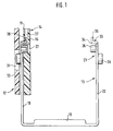
- FIG. 1 shows a locking lever, partly in section, in a top view, FIG. 2 and FIG. 3, partially in a side view, the locking lever in an unlocking or in a locking position, FIG. 4 and FIG. 5, each in a sectional view, a bearing pin of the locking lever in a closed, cup-shaped or open, sleeve-shaped configuration, mounted in a bore in a connector housing.
- An electrical coupling device which is designed as a multi-pole, elongated, electrical plug connection, has as main components a plug 11 shown in FIG. 1, a plug receptacle 12, and a locking lever 13 as part of a fastening device for the plug 11 on the plug receptacle 12 on.
- the plug 11 has a box-shaped plug housing 14 made of plastic with longitudinal walls 16 running parallel to one another.
- a protruding fastening hook is formed on a narrow side of the plug housing 14 and, when the plug 11 is joined together with the plug receptacle 12, hooks into a likewise hook-shaped holding part of the plug receptacle 12 shaped in the opposite direction to the fastening hook, forming a joint around which the plug 11 leads to the plug receptacle 12 is pivoted.
- the plug connection is closed with the aid of the locking lever 13.
- the locking lever 13 which is designed as a double-leg, U-shaped bent sheet metal part, has two side legs 18 provided with beads, which are connected on one side by a cross piece 19.
- an axis in the form of a bearing pin 26 is fastened to each side leg 18 as a first guide element, which protrudes on the inside of the side leg 18 and rotatably engages in a bore 27 in the longitudinal wall 16 of the plug housing 14 according to FIG.
- an axis in the form of a guide pin 28 is arranged on the outside of each side leg 18 as a second guide element, which can be inserted into a guide track 31 on a side wall 32 of the connector receptacle 12 and when the locking lever 13 swivels with support in the guideway 31, the plug 11 is pulled into the plug receptacle 12 and the plug connection closes.
- Bearing pin 26 and guide pin 28 are made in one piece with the locking lever 13 and are cup-shaped by means of a deep-drawing tool.
- the bearing pin 26 is shown as an example.
- the bolts 26, 28 are shaped in the form of a sleeve by means of an ironing process in the area of a previously punched-out area.
- 5 shows the bearing pin 26 as an example.
- the bolts 26, 28 formed in one piece with the locking lever 13 have at least approximately a cylindrical outer surface due to their manufacture. So that they are not secured against axial pull-out forces from their bearings, so that they can slide out of their bearings when loaded in the course of a pivoting of the locking lever 13.
- a projection 33 which extends beyond the end region 23 and lies largely in the swivel plane, is attached to each side leg 18.
- the projections 33 are rectangular in shape and each have at the attachment to the end region 23 perpendicular to the swivel plane and directed to each other bends 34 to which are located at the end in the swivel plane and parallel to the long side of the side leg 18 locking arms 36.
- the shoulders 24 themselves or other parts of the side legs 18 can also be cranked and inserted into associated locking chambers on the plug housing 14 by the pivoting movement of the locking lever 13.
- the securing function on the guide pin 28 is also possible to alternatively use the securing function on the guide pin 28 to be realized by conically widening the guide pin 28 at its free end, for example by temporarily pressing in a conical mandrel and inserting the guide pin 28 thus expanded into guideways of opposite design.
Landscapes
- Details Of Connecting Devices For Male And Female Coupling (AREA)
Applications Claiming Priority (2)
| Application Number | Priority Date | Filing Date | Title |
|---|---|---|---|
| DE4244222 | 1992-12-24 | ||
| DE4244222A DE4244222A1 (de) | 1992-12-24 | 1992-12-24 | Lösbare Steckverbindung |
Publications (3)
| Publication Number | Publication Date |
|---|---|
| EP0603542A2 true EP0603542A2 (fr) | 1994-06-29 |
| EP0603542A3 EP0603542A3 (en) | 1995-11-22 |
| EP0603542B1 EP0603542B1 (fr) | 2001-10-10 |
Family
ID=6476632
Family Applications (1)
| Application Number | Title | Priority Date | Filing Date |
|---|---|---|---|
| EP93118540A Expired - Lifetime EP0603542B1 (fr) | 1992-12-24 | 1993-11-18 | Raccord détachable à fiche |
Country Status (2)
| Country | Link |
|---|---|
| EP (1) | EP0603542B1 (fr) |
| DE (2) | DE4244222A1 (fr) |
Cited By (2)
| Publication number | Priority date | Publication date | Assignee | Title |
|---|---|---|---|---|
| EP1622232A1 (fr) * | 2004-07-30 | 2006-02-01 | Weidmüller Interface GmbH & Co. KG | Connecteur électrique avec crochets de fermeture |
| EP1763113A1 (fr) * | 2005-09-13 | 2007-03-14 | Hirschmann Automotive GmbH | Connexion mâle-femelle ayant un levier d'aide au montage et démontage |
Families Citing this family (1)
| Publication number | Priority date | Publication date | Assignee | Title |
|---|---|---|---|---|
| CN100508299C (zh) * | 2004-07-30 | 2009-07-01 | 威德米勒界面有限公司及两合公司 | 带有锁紧夹的重型电气插塞连接器 |
Citations (1)
| Publication number | Priority date | Publication date | Assignee | Title |
|---|---|---|---|---|
| DE3407725A1 (de) | 1984-03-02 | 1985-09-05 | Robert Bosch Gmbh, 7000 Stuttgart | Vielpolige steckvorrichtung |
Family Cites Families (1)
| Publication number | Priority date | Publication date | Assignee | Title |
|---|---|---|---|---|
| WO1988008212A1 (fr) * | 1987-04-04 | 1988-10-20 | Trw Daut + Rietz Gmbh & Co. Kg | Dispositif de couplage electrique |
-
1992
- 1992-12-24 DE DE4244222A patent/DE4244222A1/de not_active Ceased
-
1993
- 1993-11-18 DE DE59310222T patent/DE59310222D1/de not_active Expired - Lifetime
- 1993-11-18 EP EP93118540A patent/EP0603542B1/fr not_active Expired - Lifetime
Patent Citations (1)
| Publication number | Priority date | Publication date | Assignee | Title |
|---|---|---|---|---|
| DE3407725A1 (de) | 1984-03-02 | 1985-09-05 | Robert Bosch Gmbh, 7000 Stuttgart | Vielpolige steckvorrichtung |
Cited By (2)
| Publication number | Priority date | Publication date | Assignee | Title |
|---|---|---|---|---|
| EP1622232A1 (fr) * | 2004-07-30 | 2006-02-01 | Weidmüller Interface GmbH & Co. KG | Connecteur électrique avec crochets de fermeture |
| EP1763113A1 (fr) * | 2005-09-13 | 2007-03-14 | Hirschmann Automotive GmbH | Connexion mâle-femelle ayant un levier d'aide au montage et démontage |
Also Published As
| Publication number | Publication date |
|---|---|
| EP0603542B1 (fr) | 2001-10-10 |
| EP0603542A3 (en) | 1995-11-22 |
| DE59310222D1 (de) | 2001-11-15 |
| DE4244222A1 (de) | 1994-06-30 |
Similar Documents
| Publication | Publication Date | Title |
|---|---|---|
| DE112008000308B4 (de) | Rohrverbindungen | |
| DE102005026471B4 (de) | Halter für eine Leitung in einem Automobil | |
| DE10114023B4 (de) | Montagestütze zur Befestigung eines Zubehörteils an einer Fahrzeugkarosserie | |
| DE102004021117A1 (de) | Kraftstoffeinspritzvorrichtung | |
| DE10164856B4 (de) | Steckverbinder mit einem Verriegelungssicherungsmechanismus | |
| DE102017125771A1 (de) | Fahrzeugkomponenten-Befestiger mit verbesserter Vorverrastung | |
| EP0790153B1 (fr) | Dispositif de fixation d'un module de sac de sécurité gonflable | |
| EP1770320B1 (fr) | Raccord détachable à fiche pour des tuyaux | |
| DE3509831A1 (de) | Scheinwerfer fuer kraftfahrzeuge | |
| DE60320131T2 (de) | Verfahren und vorrichtung zur herstellung eines rechtwinkligen steckanschlusses für rohrleitungen | |
| DE102017118014B3 (de) | Steckverbinderteil mit einem Verriegelungselement | |
| EP1095431B1 (fr) | Connecteur electrique enfichable | |
| DE4106817A1 (de) | Einrichtung und verfahren zum verbinden einer schraubenspindel und eines antriebskabels in einer schultergurt-positionseinstelleinrichtung | |
| EP0603542A2 (fr) | Raccord détachable à fiche | |
| DE3908617A1 (de) | Automatisch montierbarer und beleuchteter elektrischer zigarrenanzuender | |
| DE102006036971B4 (de) | Adaptersystem | |
| DE10326834B4 (de) | Steckverbinder | |
| EP0976607B1 (fr) | Dispositif pour la fixation d'un siège d'enfant sur un siège de véhicule | |
| DE2739991A1 (de) | Kupplungsgelenk | |
| DE4321303C1 (de) | Vorrichtung zum Befestigen eines Verkleidungsteiles an einem Karosserieteil | |
| DE4141834C1 (fr) | ||
| DE10208505B4 (de) | Verbindungselement, Anordnung aus Verkleidungsteil mit Verbindungselement und Dichtungsprofil und Verfahren zur Montage | |
| EP1462310B1 (fr) | Module de colonne de direction | |
| DE1500840A1 (de) | Mechanische Kupplung | |
| DE602004001826T2 (de) | Verfahren zur Befestigung eine Steuereinrichtung eines Kraftfahrzeuges und vorübergehende Befestigungungsvorrichtung zur Durchführung des Verfahrens |
Legal Events
| Date | Code | Title | Description |
|---|---|---|---|
| PUAI | Public reference made under article 153(3) epc to a published international application that has entered the european phase |
Free format text: ORIGINAL CODE: 0009012 |
|
| AK | Designated contracting states |
Kind code of ref document: A2 Designated state(s): DE FR IT SE |
|
| PUAL | Search report despatched |
Free format text: ORIGINAL CODE: 0009013 |
|
| AK | Designated contracting states |
Kind code of ref document: A3 Designated state(s): DE FR IT SE |
|
| 17P | Request for examination filed |
Effective date: 19960522 |
|
| 17Q | First examination report despatched |
Effective date: 19981124 |
|
| GRAG | Despatch of communication of intention to grant |
Free format text: ORIGINAL CODE: EPIDOS AGRA |
|
| GRAG | Despatch of communication of intention to grant |
Free format text: ORIGINAL CODE: EPIDOS AGRA |
|
| GRAH | Despatch of communication of intention to grant a patent |
Free format text: ORIGINAL CODE: EPIDOS IGRA |
|
| GRAH | Despatch of communication of intention to grant a patent |
Free format text: ORIGINAL CODE: EPIDOS IGRA |
|
| GRAA | (expected) grant |
Free format text: ORIGINAL CODE: 0009210 |
|
| AK | Designated contracting states |
Kind code of ref document: B1 Designated state(s): DE FR IT SE |
|
| REF | Corresponds to: |
Ref document number: 59310222 Country of ref document: DE Date of ref document: 20011115 |
|
| ET | Fr: translation filed | ||
| PLBE | No opposition filed within time limit |
Free format text: ORIGINAL CODE: 0009261 |
|
| STAA | Information on the status of an ep patent application or granted ep patent |
Free format text: STATUS: NO OPPOSITION FILED WITHIN TIME LIMIT |
|
| 26N | No opposition filed | ||
| PGFP | Annual fee paid to national office [announced via postgrant information from national office to epo] |
Ref country code: SE Payment date: 20081124 Year of fee payment: 16 Ref country code: IT Payment date: 20081126 Year of fee payment: 16 |
|
| PGFP | Annual fee paid to national office [announced via postgrant information from national office to epo] |
Ref country code: FR Payment date: 20081118 Year of fee payment: 16 |
|
| EUG | Se: european patent has lapsed | ||
| REG | Reference to a national code |
Ref country code: FR Ref legal event code: ST Effective date: 20100730 |
|
| PG25 | Lapsed in a contracting state [announced via postgrant information from national office to epo] |
Ref country code: FR Free format text: LAPSE BECAUSE OF NON-PAYMENT OF DUE FEES Effective date: 20091130 |
|
| PG25 | Lapsed in a contracting state [announced via postgrant information from national office to epo] |
Ref country code: IT Free format text: LAPSE BECAUSE OF NON-PAYMENT OF DUE FEES Effective date: 20091118 |
|
| PG25 | Lapsed in a contracting state [announced via postgrant information from national office to epo] |
Ref country code: SE Free format text: LAPSE BECAUSE OF NON-PAYMENT OF DUE FEES Effective date: 20091119 |
|
| PGFP | Annual fee paid to national office [announced via postgrant information from national office to epo] |
Ref country code: DE Payment date: 20110125 Year of fee payment: 18 |
|
| REG | Reference to a national code |
Ref country code: DE Ref legal event code: R119 Ref document number: 59310222 Country of ref document: DE Effective date: 20120601 |
|
| PG25 | Lapsed in a contracting state [announced via postgrant information from national office to epo] |
Ref country code: DE Free format text: LAPSE BECAUSE OF NON-PAYMENT OF DUE FEES Effective date: 20120601 |