EP0602992B1 - Une combinaison d'un réseau de diffraction et d'un prisme - Google Patents
Une combinaison d'un réseau de diffraction et d'un prisme Download PDFInfo
- Publication number
- EP0602992B1 EP0602992B1 EP93310205A EP93310205A EP0602992B1 EP 0602992 B1 EP0602992 B1 EP 0602992B1 EP 93310205 A EP93310205 A EP 93310205A EP 93310205 A EP93310205 A EP 93310205A EP 0602992 B1 EP0602992 B1 EP 0602992B1
- Authority
- EP
- European Patent Office
- Prior art keywords
- grating
- prism
- optical element
- dispersive optical
- element according
- Prior art date
- Legal status (The legal status is an assumption and is not a legal conclusion. Google has not performed a legal analysis and makes no representation as to the accuracy of the status listed.)
- Expired - Lifetime
Links
- 230000003287 optical effect Effects 0.000 claims description 46
- 230000003595 spectral effect Effects 0.000 claims description 39
- 230000004304 visual acuity Effects 0.000 claims description 35
- 230000005855 radiation Effects 0.000 claims description 17
- 239000000463 material Substances 0.000 claims description 10
- 238000003384 imaging method Methods 0.000 claims description 5
- 238000010521 absorption reaction Methods 0.000 claims description 3
- 238000001228 spectrum Methods 0.000 claims description 2
- 238000010586 diagram Methods 0.000 description 9
- 239000006185 dispersion Substances 0.000 description 6
- 230000003321 amplification Effects 0.000 description 2
- 238000003199 nucleic acid amplification method Methods 0.000 description 2
- 230000004075 alteration Effects 0.000 description 1
- 238000004458 analytical method Methods 0.000 description 1
- 150000001875 compounds Chemical class 0.000 description 1
- 230000007812 deficiency Effects 0.000 description 1
- 238000001514 detection method Methods 0.000 description 1
- 239000003814 drug Substances 0.000 description 1
- 230000005670 electromagnetic radiation Effects 0.000 description 1
- 230000007613 environmental effect Effects 0.000 description 1
- 238000004519 manufacturing process Methods 0.000 description 1
- 239000000203 mixture Substances 0.000 description 1
- 230000004048 modification Effects 0.000 description 1
- 238000012986 modification Methods 0.000 description 1
- 238000005070 sampling Methods 0.000 description 1
- 238000000926 separation method Methods 0.000 description 1
Images


Classifications
-
- G—PHYSICS
- G02—OPTICS
- G02B—OPTICAL ELEMENTS, SYSTEMS OR APPARATUS
- G02B27/00—Optical systems or apparatus not provided for by any of the groups G02B1/00 - G02B26/00, G02B30/00
- G02B27/42—Diffraction optics, i.e. systems including a diffractive element being designed for providing a diffractive effect
- G02B27/4233—Diffraction optics, i.e. systems including a diffractive element being designed for providing a diffractive effect having a diffractive element [DOE] contributing to a non-imaging application
- G02B27/4244—Diffraction optics, i.e. systems including a diffractive element being designed for providing a diffractive effect having a diffractive element [DOE] contributing to a non-imaging application in wavelength selecting devices
-
- G—PHYSICS
- G01—MEASURING; TESTING
- G01J—MEASUREMENT OF INTENSITY, VELOCITY, SPECTRAL CONTENT, POLARISATION, PHASE OR PULSE CHARACTERISTICS OF INFRARED, VISIBLE OR ULTRAVIOLET LIGHT; COLORIMETRY; RADIATION PYROMETRY
- G01J3/00—Spectrometry; Spectrophotometry; Monochromators; Measuring colours
- G01J3/12—Generating the spectrum; Monochromators
- G01J3/14—Generating the spectrum; Monochromators using refracting elements, e.g. prisms
-
- G—PHYSICS
- G02—OPTICS
- G02B—OPTICAL ELEMENTS, SYSTEMS OR APPARATUS
- G02B5/00—Optical elements other than lenses
- G02B5/04—Prisms
-
- G—PHYSICS
- G02—OPTICS
- G02B—OPTICAL ELEMENTS, SYSTEMS OR APPARATUS
- G02B5/00—Optical elements other than lenses
- G02B5/18—Diffraction gratings
- G02B5/1814—Diffraction gratings structurally combined with one or more further optical elements, e.g. lenses, mirrors, prisms or other diffraction gratings
Definitions
- the present invention contains subject matter which is related to copending U.S. Patent Application entitled “Achromatic and Apochromatic prism element employing prisms and gratings” Serial No.: 07/989417 (EP-A-0 601 873), which is assigned as the same assignee as the present application.
- This invention relates to dispersive optical elements, and particularly to a dispersive optical element having characteristics of both prisms and a gratings.
- Dispersive optical elements have many important uses. Such elements disperse light by deviating the path of light passing through them by an amount that varies with wavelength. Prisms and gratings are the two most widely used dispersive optical elements. Prisms disperse light because their geometry causes light of different wavelengths passing through them to be separated and deviated by different amounts. In diffraction gratings light passing through the grating is diffracted into a series of orders caused by the interference of wavefronts emitted from each slit in the grating.
- One important application of dispersive optical elements is the production of spectrometers. Spectrometers have important applications in many fields such as medicine, material sciences, chemistry, environmental sciences, etc. Spectrometers use dispersive optical elements such as gratings or prisms, to permit the analysis of the spectral composition of sampled light.
- Grating spectrometers and prism spectrometers each have various advantages and disadvantages.
- the resolving power of a prism has large variations over wide spectral bands. This is because a prism's resolving power is a function of the prism material dispersion, which varies in a highly non-linear fashion with wavelengths. In most cases, the resolving power for a prism does not match the desired spectral characteristic curve regardless of the choice of materials. For example, where wide spectral coverage is desired the wide variation in the resolving power of a prism spectrometer over this wide spectral band severally limits its usefulness.
- Spectrometers utilizing gratings have other disadvantages.
- the grating can typically be used over only one diffractive order since the optical efficiency in other orders will be very low. This limits the flexibility of the grating.
- the wide separation of light for different diffractive orders may prevent their detection in a single detector thus limiting their usefulness in many applications.
- the resolving power of a grating is independent of a wavelength. As a result, the dynamic range of the resolving power is fixed and can not be adapted to fit a desired spectrometer specification.
- the dynamic range of the resolving power is the variation in the resolving power with wavelength.
- a resolving power of 100 in the wavelength range of 25 to 26 microns and a resolving power of 1000 in the wavelength range of 5 to 7 microns.
- a dispersive optical element with a predefined resolving power characteristic curve. It may be desired that the curve be linear, constant or some other defined curve. Whether one chooses prisms or gratings, the flexibility to achieve a desire curve is severally limited.
- dispersive optical element that is more flexible in its dispersive characteristics than gratings or prisms. Further, it would be desirable to provide a dispersive optical element in which the spectral curve of the resolving power can be predetermined with greater specificity than is possible with either gratings or prisms. Further, it would be desirable to provide such a dispersive optical element that is simple and can be produced at relatively low cost.
- the present invention provides a dispersive optical element having a predetermined dynamic range of resolving power comprising:
- the present invention is a dispersive optical element utilizing both a grating and a prism. Accordingly, this dispersive optical element will be called a "grism".
- a grism utilizes the unique properties of both a prism and a grating. These unique properties will be discussed in more detail below. While the preferred embodiment of the present invention utilizes the prism in a spectrometer, it will be appreciated that the other uses may be employed for a grism based on the teachings of the present invention. These include aberration correction, wavefront sampling, multiple beams combining, etc.
- Electromagnetic radiation 12 which will be typically anywhere between infrared and ultra-violet wavelengths, enters the spectrometer through an entrance slit 14.
- the radiation 12 is collimated by a set of collimating optics 16 and then enters a prism 18 having first 20 and second surfaces 22.
- the dispersed radiation emitted from the prism 18 then enters a set of imaging optics 24, which focusses the radiation onto a detector 26.
- the dispersion of the radiation 12 by the prism 18 will cause the radiation to be angularly separated for different wavelengths on the detector 26.
- the image on the detector 26 will consist of separated chromatic slit images.
- FIG. 2 A typical grating spectrometer 28 is shown in FIG. 2.
- This grating spectrometer 28 is a well known configuration commonly known as Czerny-Turner Mounting.
- Optical radiation 30 enters the spectrometer 28 through an entrance slit 32 and is reflected and collimated by a collimating optics unit 34 which serves the same function as the collimating optic 16 in FIG. 1.
- the optical radiation 30 is then reflected onto a grating 36, which is a reflection type grating that serves a dispersive function similar to that of prism 18 in FIG. 1.
- the optical radiation is then reflected by imaging optics 38 which focusses the optical radiation onto a detector (not shown) through a exit slit 40.
- the resolving power of the grating spectrometer 28 is p x m, where p is the diffracted order and m is the total number of grating lines in the grating 36. This illustrates that the resolving power of the grating 36 is independent of wavelength.
- FIG. 3 is a schematic diagram of a grism spectrometer 42 in accordance with a first preferred embodiment of the present invention.
- Optical radiation 44 enters the spectrometer through an entrance slit 46 and is collimated by conventional collimating optics 48. The light then enters the grism 50 where it is dispersed. The optical radiation 44 is then focused by an imaging optics unit 52 into a spectrum on a detector 54.
- the grism 50 comprises a prism 56 having a first surface 58 and second surface 60.
- a grating 62 is etched onto the second surface 60 of the prism.
- grating 62 may be mounted to the first surface 58 of the prism, or comprise a reflective grating instead of the transmissive grating 62.
- the optical radiation 44 may pass through the prism and impinge upon the reflective grating on the second surface of the prism and then pass through the prism again in the opposite direction.
- the collimating optics could also be used as the imaging optics.
- the grating may be attached to the prism by other means, or may comprise a separate grating placed adjacent to the prism and not actually attached. Further it will be appreciated that many different kinds of gratings can be used, such as a blazed grating, binary optics, volume hologram, surface relief hologram, or an absorption grating.
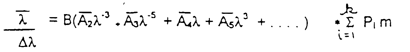
- the resolving power of a "grism" is where B is the prism base width, A i 's are the constants used to describe the slope of the index of refraction as a function of wavelength, P i is the diffractive order of the i'th spectral band of the grating 62, k is the total number of spectral bands involved, and m is the number of lines in the grating 62.
- B is the prism base width
- a i 's are the constants used to describe the slope of the index of refraction as a function of wavelength
- P i is the diffractive order of the i'th spectral band of the grating 62
- k is the total number of spectral bands involved
- m is the number of lines in the grating 62.
- the resolving power is controlled by the grating period m and the diffraction order p.
- the grating efficiency is controlled by the parameters related to the diffraction mechanism. For instance, the diffraction efficiency of a blazed grating is a function of the ratio of the blazed width to the grating period. On the other hand, the diffraction efficiency of a volume hologram is a function of the modulation of the index of refraction.
- FIGS. 4, 5, and 6 are referred to as the equally-diffracted grism, the partially-diffracted grism, and unequally-diffracted grism.
- FIG. 4A-B an equally-diffracted grism in accordance with a second preferred embodiment of the present invention is shown.
- FIG. 4A illustrates a conventional prism 64 in which radiation having average wavelength in three spectral bands is diffracted by the prism 64 as shown. These three spectral bands may comprise, for example, 1, 2, and 4 micrometers.
- FIG. 4B a grism 66 in accordance with the present invention is shown.
- the grism 66 includes a grating 68 and prism 70.
- the same three spectral bands as in FIG. 4A are now diffracted by the grism 66 using the same diffractive order.
- each of the three bands are diffracted into the minus 1 order. That is, the P i 's in equation 4 are all the same.
- the grism 65 has amplified the angular spread of the three bands as compared to the prism alone.
- This amplification has many advantages which may be used in a number of ways depending upon the application. For example, this amplification of angular spread may be used to increase the resolution of a spectrometer.
- a grism 72 in accordance with a third embodiment of the present invention is shown in the partially-diffracted grism arrangement.
- the grism 72 which includes grating 74 and prism 76 is similar to that of grism 66 in FIG. 4B except that the zeroth diffractive order is used.
- all three spectral bands are first dispersed by the prism. Band three is then further diffracted by the grating 74 using the first order. Bands one and two are outside of the grating diffraction envelope. Thus, very little radiation in bands one and two is diffracted into other orders except the zeroth order. As a consequence, there is no further angular spread for bands one and two.
- FIG. 6 shows a third variation in which a grism 78 having a grating 80 and a prism 82 results in an "unequal-diffracted grism, where bands 1, 2 and 3 are diffracted by the grating each using different diffractive orders.
- This arrangement not only has very good resolving power due to the use of the higher diffraction orders, but also the size of the resulting spectrometer can also be made very compact.
- the selection of each of the three types of grisms shown in FIGS. 4B, 5, and 6 are designed using equation 4. That is, by selection of the parameters such as the number of grating lines, and diffractive order for each particular spectral band.
- the grating is a blazed grating
- the desired configuration is achieved by manipulating the parameter of the grating equation to achieve the blazed condition for the desired bands.
- the prism used may be replaced by a compound prism consisting of several prisms with different types of materials and proper prism angles.
- the desired performance can be achieved as defined by equation 4 above.
- the present invention permits the distribution of resolving power between the prism and the grating to yield a grism in which the dynamic range of the resolving power is greatly improved. Further, the selection of the proper diffraction orders can result in a further enhancement of the resolving power by adjusting the diffraction efficiency function. Additional adjustments of the efficiency function of the grism can be achieved through the use of various types of gratings including blazed gratings, binary gratings, volume phase gratings, surface relief gratings, or absorption gratings.
Claims (14)
- Élément optique dispersif (50,66,72,78) ayant une gamme dynamique prédéterminée de pouvoir de résolution, comprenant :caractérisé en ce que le pouvoir de résolution de l'élément optique dispersif (50,66,72,78) est défini par l'expression :un prisme (56,70,76,82) ayant des première et seconde surfaces (58,60) définissant un angle de prisme et une base opposée à l'angle de prisme ; etdes moyens à réseau de diffraction (62,68,74,80) adjacents à une surface du prisme (56,70,76,82), les moyens à réseau de diffraction (62,68,74,80) étant conçus pour disperser un rayonnement ayant des bandes spectrales multiples (λ, λ2, λ3) ;
 où λ est la longueur d'onde de la lumière,
λ est la longueur d'onde moyenne d'une bande spectrale de lumière, B est la largeur de base du prisme, lesA i's sont des constantes utilisées pour décrire la pente de l'indice de réfraction du prisme en fonction de la longueur d'onde, Pi est l'ordre de diffraction de la ième bande spectrale du réseau de diffraction, k est le nombre total de bandes spectrales concernées, et m est le nombre de lignes dans le réseau de diffraction,Pi étant sélectionné pour fournir un ordre de diffraction prédéterminé pour chaque bande spectrale afin de produire ainsi la gamme dynamique prédéterminée de pouvoir de résolution. - Élément optique dispersif selon la revendication 1, dans lequel lesdites bandes spectrales multiples comprennent des première, seconde et troisième bandes spectrales et Pi est sélectionné de façon à fournir le même ordre de diffraction pour lesdites première, seconde et troisième bandes spectrales afin d'amplifier ainsi l'étalement angulaire de la diffraction par le prisme.
- Élément optique dispersif selon la revendication 1, dans lequel lesdites bandes spectrales multiples comprennent des première, seconde et troisième bandes spectrales et Pi est sélectionné de façon à fournir un premier ordre de diffraction pour lesdites première et seconde bandes spectrales et un second ordre de diffraction pour ladite troisième bande spectrale.
- Élément optique dispersif selon la revendication 1, dans lequel lesdites bandes spectrales multiples comprennent des première, seconde et troisième bandes spectrales et Pi est sélectionné de façon à fournir un premier ordre de diffraction pour ladite première bande spectrale, un second ordre de diffraction pour ladite seconde bande spectrale et un troisième ordre de diffraction pour ladite troisième bande spectrale.
- Élément optique dispersif selon l'une quelconque des revendications précédentes, dans lequel le réseau de diffraction (62,68,74,80) est un réseau de diffraction de transmission.
- Élément optique dispersif selon la revendication 5, dans lequel le réseau de diffraction (62,68,74,80) est fixé à la première surface (58) ou à la seconde surface (60) du prisme (56,70,76,82).
- Élément optique dispersif selon l'une quelconque des revendications 1-4, dans lequel le réseau de diffraction (62,68,74,80) est un réseau de diffraction de réflexion fixé à la seconde surface (60) du prisme (56,70,76,82).
- Élément optique dispersif selon l'une quelconque des revendications précédentes, dans lequel le réseau de diffraction (62,68,74,80) est un réseau de diffraction rainuré.
- Élément optique dispersif selon l'une quelconque des revendications précédentes, dans lequel le réseau de diffraction (62,68,74,80) est un réseau de diffraction optique binaire.
- Élément optique dispersif selon l'une quelconque des revendications précédentes, dans lequel le réseau de diffraction (62,68,74,80) est un hologramme de volume.
- Élément optique dispersif selon l'une quelconque des revendications précédentes, dans lequel le réseau de diffraction (62,68,74,80) est un hologramme à relief de surface.
- Élément optique dispersif selon l'une quelconque des revendications précédentes, dans lequel le réseau de diffraction (62,68,74,80) est un réseau de diffraction d'absorption.
- Élément optique dispersif selon l'une quelconque des revendications précédentes, dans lequel le prisme (56,70,76,82) comprend une pluralité de prismes composés de différents matériaux.
- Spectromètre comprenant :(a) des moyens d'entrée de lumière ;(b) des moyens optiques de collimation pour collimater la lumière pénétrant dans ledit spectromètre à travers lesdits moyens d'entrée de lumière ;(c) un élément optique dispersif selon l'une quelconque des revendications précédentes ; et(d) des moyens optiques de formation d'image pour focaliser la lumière dispersée par l'élément optique dispersif dans un spectre.
Applications Claiming Priority (2)
| Application Number | Priority Date | Filing Date | Title |
|---|---|---|---|
| US99334492A | 1992-12-18 | 1992-12-18 | |
| US993344 | 1992-12-18 |
Publications (2)
| Publication Number | Publication Date |
|---|---|
| EP0602992A1 EP0602992A1 (fr) | 1994-06-22 |
| EP0602992B1 true EP0602992B1 (fr) | 1999-03-03 |
Family
ID=25539422
Family Applications (1)
| Application Number | Title | Priority Date | Filing Date |
|---|---|---|---|
| EP93310205A Expired - Lifetime EP0602992B1 (fr) | 1992-12-18 | 1993-12-17 | Une combinaison d'un réseau de diffraction et d'un prisme |
Country Status (4)
| Country | Link |
|---|---|
| US (1) | US5652681A (fr) |
| EP (1) | EP0602992B1 (fr) |
| JP (1) | JPH06230206A (fr) |
| DE (1) | DE69323702T2 (fr) |
Families Citing this family (53)
| Publication number | Priority date | Publication date | Assignee | Title |
|---|---|---|---|---|
| DE69325783T2 (de) | 1992-12-11 | 1999-11-18 | Raytheon Co | Achromatisches und apochromatisches Prismenelement aus Prisma und Gittern |
| US6017434A (en) * | 1995-05-09 | 2000-01-25 | Curagen Corporation | Apparatus and method for the generation, separation, detection, and recognition of biopolymer fragments |
| US5892620A (en) * | 1995-10-03 | 1999-04-06 | Stone; Thomas W. | Optical shuffle device |
| WO2005022705A2 (fr) * | 1997-03-21 | 2005-03-10 | Imra America, Inc. | Amplificateur a fibre optique haute energie pour impulsions picoseconde-nanoseconde destinees a des applications de traitement de materiaux hautes performances |
| JP2001521250A (ja) * | 1997-10-27 | 2001-11-06 | マサチューセッツ・インスティチュート・オブ・テクノロジー | 情報の検索および検索システム |
| US6441934B1 (en) * | 1998-02-13 | 2002-08-27 | Apa Optics, Inc. | Multiplexer and demultiplexer for single mode optical fiber communication links |
| US6831781B2 (en) * | 1998-02-26 | 2004-12-14 | The General Hospital Corporation | Confocal microscopy with multi-spectral encoding and system and apparatus for spectroscopically encoded confocal microscopy |
| US6320191B1 (en) | 1998-03-27 | 2001-11-20 | Picometrix, Inc. | Dispersive precompensator for use in an electromagnetic radiation generation and detection system |
| US6795473B1 (en) * | 1999-06-23 | 2004-09-21 | Lambda Physik Ag | Narrow band excimer laser with a prism-grating as line-narrowing optical element |
| US6490307B1 (en) | 1999-03-17 | 2002-12-03 | Lambda Physik Ag | Method and procedure to automatically stabilize excimer laser output parameters |
| US6965624B2 (en) * | 1999-03-17 | 2005-11-15 | Lambda Physik Ag | Laser gas replenishment method |
| US6678291B2 (en) | 1999-12-15 | 2004-01-13 | Lambda Physik Ag | Molecular fluorine laser |
| US6389052B2 (en) | 1999-03-17 | 2002-05-14 | Lambda Physik Ag | Laser gas replenishment method |
| US6421365B1 (en) | 1999-11-18 | 2002-07-16 | Lambda Physik Ag | Narrow band excimer or molecular fluorine laser having an output coupling interferometer |
| US6727731B1 (en) | 1999-03-12 | 2004-04-27 | Lambda Physik Ag | Energy control for an excimer or molecular fluorine laser |
| US6714577B1 (en) | 1999-03-17 | 2004-03-30 | Lambda Physik Ag | Energy stabilized gas discharge laser |
| DE29907349U1 (de) | 1999-04-26 | 2000-07-06 | Lambda Physik Gmbh | Laser zur Erzeugung schmalbandiger Strahlung |
| AU1326401A (en) * | 1999-07-29 | 2001-02-19 | Apa Optics, Inc. | Dense wavelength division muliplexer (dwdm) |
| US6693745B1 (en) | 1999-09-14 | 2004-02-17 | Corning Incorporated | Athermal and high throughput gratings |
| US6553050B1 (en) | 1999-11-18 | 2003-04-22 | Lambda Physik Ag | Narrow band excimer or molecular fluorine laser having an output coupling interferometer |
| US6603788B1 (en) | 1999-11-23 | 2003-08-05 | Lambda Physik Ag | Resonator for single line selection |
| DE10190427T1 (de) | 2000-01-25 | 2002-06-06 | Lambda Physik Ag | Energieüberwachungsvorrichtung für einen Fluormolekül-Laser |
| JP3920014B2 (ja) * | 2000-08-24 | 2007-05-30 | フジノン株式会社 | 色消しビーム整形プリズム |
| US6589716B2 (en) * | 2000-12-20 | 2003-07-08 | Sandia Corporation | Microoptical system and fabrication method therefor |
| US6912330B2 (en) * | 2001-05-17 | 2005-06-28 | Sioptical Inc. | Integrated optical/electronic circuits and associated methods of simultaneous generation thereof |
| US6947615B2 (en) | 2001-05-17 | 2005-09-20 | Sioptical, Inc. | Optical lens apparatus and associated method |
| US6603889B2 (en) | 2001-05-17 | 2003-08-05 | Optronx, Inc. | Optical deflector apparatus and associated method |
| US6788051B2 (en) | 2001-07-31 | 2004-09-07 | Raytheon Company | Method and system of spectroscopic measurement of magnetic fields |
| US6998620B2 (en) * | 2001-08-13 | 2006-02-14 | Lambda Physik Ag | Stable energy detector for extreme ultraviolet radiation detection |
| US20030090763A1 (en) * | 2001-11-13 | 2003-05-15 | Adc Telecommunications, Inc. | Echelle grating interleaver |
| US6661513B1 (en) * | 2001-11-21 | 2003-12-09 | Roygbiv, Llc | Refractive-diffractive spectrometer |
| US7408638B2 (en) * | 2001-11-21 | 2008-08-05 | Roygbiv, Llc | Refractive-diffractive spectrometer |
| JP3576538B2 (ja) | 2002-06-11 | 2004-10-13 | 独立行政法人理化学研究所 | グリズム |
| FR2847668B1 (fr) * | 2002-11-25 | 2005-12-16 | Jobin Yvon Sas | Spectrometre axial a haute resolution spatiale et spectrale et domaine spectrale d'observation variable |
| US6965475B2 (en) * | 2003-03-28 | 2005-11-15 | Sumitomo Electric Industries, Ltd. | Optical component, optical device and optical communications system |
| JP2004361730A (ja) * | 2003-06-05 | 2004-12-24 | Yoshiharu Mizoguchi | 万華鏡 |
| US7813644B2 (en) * | 2004-05-10 | 2010-10-12 | Raytheon Company | Optical device with a steerable light path |
| US7038863B2 (en) | 2004-06-02 | 2006-05-02 | Raytheon Company | Compact, wide-field-of-view imaging optical system |
| US7508853B2 (en) | 2004-12-07 | 2009-03-24 | Imra, America, Inc. | Yb: and Nd: mode-locked oscillators and fiber systems incorporated in solid-state short pulse laser systems |
| US20060207976A1 (en) * | 2005-01-21 | 2006-09-21 | Bovatsek James M | Laser material micromachining with green femtosecond pulses |
| US7593434B2 (en) * | 2005-06-30 | 2009-09-22 | Polaronyx, Inc. | Compression design for high energy short pulse fiber laser |
| US7817274B2 (en) | 2007-10-05 | 2010-10-19 | Jingyun Zhang | Compact spectrometer |
| WO2009070459A1 (fr) | 2007-11-30 | 2009-06-04 | Jingyun Zhang | Spectromètres miniatures fonctionnant avec des téléphones cellulaires et autres dispositifs électroniques portables |
| EP2252426A4 (fr) | 2008-03-21 | 2014-08-06 | Imra America Inc | Procédés et systèmes de traitement au laser de matériaux |
| US7751461B2 (en) * | 2008-08-01 | 2010-07-06 | Newport Corporation | Linewidth-narrowed excimer laser cavity |
| JP2010128473A (ja) * | 2008-12-01 | 2010-06-10 | Olympus Corp | 分散素子及び分散素子を備える光学機器 |
| US8203789B1 (en) | 2008-12-01 | 2012-06-19 | Capella Photonics, Inc. | Double-pass diffraction grating |
| CN102905839B (zh) | 2010-03-30 | 2016-03-09 | Imra美国公司 | 基于激光的材料加工装置和方法 |
| US8294988B2 (en) | 2010-09-02 | 2012-10-23 | Raytheon Company | Dual field of view refractive optical system with external pupil and internal stabilization |
| US9601904B1 (en) | 2015-12-07 | 2017-03-21 | Raytheon Company | Laser diode driver with variable input voltage and variable diode string voltage |
| CN110081976A (zh) * | 2019-05-21 | 2019-08-02 | 中国科学院光电研究院 | 一种大视场光栅棱镜光谱成像系统 |
| KR20210035380A (ko) * | 2019-09-23 | 2021-04-01 | 삼성전자주식회사 | 광학계, 광학계를 포함하는 카메라 모듈, 및 카메라 모듈을 포함하는 기기 |
| US11536607B2 (en) | 2020-01-17 | 2022-12-27 | Samsung Electronics Co., Ltd. | Image sensor and method of operating |
Family Cites Families (13)
| Publication number | Priority date | Publication date | Assignee | Title |
|---|---|---|---|---|
| US3900263A (en) * | 1974-01-04 | 1975-08-19 | Jr Joseph F Hall | Method for minimizing deviation in optical dispersion systems |
| SU706711A1 (ru) * | 1978-07-11 | 1979-12-30 | Новосибирский институт инженеров геодезии, аэрофотосъемки и картографии | Монохроматор |
| JPS5529824A (en) * | 1978-08-24 | 1980-03-03 | Nippon Telegr & Teleph Corp <Ntt> | Photo branching filter |
| GB2065919B (en) * | 1979-11-07 | 1984-10-17 | Canon Kk | Focussing screen |
| US4338012A (en) * | 1980-10-31 | 1982-07-06 | Canon Kabushiki Kaisha | Focusing screen |
| US4411492A (en) * | 1981-02-11 | 1983-10-25 | United Technologies Corporation | Dispersionless refractor for use with high-power lasers |
| US4475792A (en) * | 1982-07-27 | 1984-10-09 | The United States Of America As Represented By The Secretary Of The Navy | High resolution diffraction grating |
| JPS5957205A (ja) * | 1982-09-27 | 1984-04-02 | Fujitsu Ltd | 光学帯域反射フイルタ |
| US4973112A (en) * | 1988-12-01 | 1990-11-27 | Holotek Ltd. | Hologon deflection system having dispersive optical elements for scan line bow correction, wavelength shift correction and scanning spot ellipticity correction |
| DE3843876A1 (de) * | 1988-12-24 | 1990-07-12 | Leitz Wild Gmbh | Spektralmikroskop mit einem photometer |
| GB9007912D0 (en) * | 1990-04-06 | 1990-06-06 | British Telecomm | A method of forming a refractive index grating in an optical waveguide |
| US5101458A (en) * | 1990-11-08 | 1992-03-31 | The University Of Rochester | Achromatic input/output coupler for integrated optical circuits |
| US5420947A (en) * | 1994-06-17 | 1995-05-30 | Eastman Kodak Company | Method for achromatically coupling a beam of light into a waveguide |
-
1993
- 1993-12-17 EP EP93310205A patent/EP0602992B1/fr not_active Expired - Lifetime
- 1993-12-17 DE DE69323702T patent/DE69323702T2/de not_active Expired - Lifetime
- 1993-12-20 JP JP5320483A patent/JPH06230206A/ja active Pending
-
1996
- 1996-01-11 US US08/584,991 patent/US5652681A/en not_active Expired - Lifetime
Also Published As
| Publication number | Publication date |
|---|---|
| JPH06230206A (ja) | 1994-08-19 |
| DE69323702T2 (de) | 1999-07-22 |
| DE69323702D1 (de) | 1999-04-08 |
| US5652681A (en) | 1997-07-29 |
| EP0602992A1 (fr) | 1994-06-22 |
Similar Documents
| Publication | Publication Date | Title |
|---|---|---|
| EP0602992B1 (fr) | Une combinaison d'un réseau de diffraction et d'un prisme | |
| US5442439A (en) | Spectrograph with multiplexing of different wavelength regions onto a single opto-electric detector array | |
| US5139335A (en) | Holographic grating imaging spectrometer | |
| US4634276A (en) | Slit imaging system using two concave mirrors | |
| US11307096B2 (en) | Spectral resolution enhancement device | |
| US5859702A (en) | Apparatus for carrying out spectral analysis of an optical light source using image detection and separation of spectral orders | |
| US4729658A (en) | Very wide spectral coverage grating spectrometer | |
| US6628383B1 (en) | Imaging spectrograph for multiorder spectroscopy | |
| US5189486A (en) | Echelle polychromator | |
| US6816258B2 (en) | Dispersive spectrometer | |
| US7839550B1 (en) | Volume holographic filter with broad acceptance angle and narrow spectral bandwidth | |
| US6713770B2 (en) | High resolution spectral measurement device | |
| US5402227A (en) | High resolution multiple channel imaging spectrometer | |
| US20010052980A1 (en) | Spectroscope for measuring spectral distribution | |
| JP2000304614A (ja) | 分光装置 | |
| US4684253A (en) | Apparatus for carrying out spectral analysis | |
| Hayat et al. | Designing a new generation of analytical instruments around the new types of holographic diffraction grating | |
| USH1152H (en) | Imaging channeled spectrograph | |
| US3062089A (en) | Grating monochromators | |
| EP2211154B1 (fr) | Monochromateur à réseau accordable | |
| Barden et al. | Astronomical applications of volume-phase holographic gratings | |
| Murty et al. | Design and fabrication of a Czerny-Turner monochromator-cum-spectrograph | |
| US7480048B1 (en) | Monochromator employing single grating volume holograms and method of use | |
| JP3278257B2 (ja) | 複単色計 | |
| US3052795A (en) | Radiation dispersion system |
Legal Events
| Date | Code | Title | Description |
|---|---|---|---|
| PUAI | Public reference made under article 153(3) epc to a published international application that has entered the european phase |
Free format text: ORIGINAL CODE: 0009012 |
|
| AK | Designated contracting states |
Kind code of ref document: A1 Designated state(s): CH DE FR GB LI |
|
| 17P | Request for examination filed |
Effective date: 19941125 |
|
| 17Q | First examination report despatched |
Effective date: 19970212 |
|
| GRAG | Despatch of communication of intention to grant |
Free format text: ORIGINAL CODE: EPIDOS AGRA |
|
| GRAG | Despatch of communication of intention to grant |
Free format text: ORIGINAL CODE: EPIDOS AGRA |
|
| GRAH | Despatch of communication of intention to grant a patent |
Free format text: ORIGINAL CODE: EPIDOS IGRA |
|
| RAP1 | Party data changed (applicant data changed or rights of an application transferred) |
Owner name: RAYTHEON COMPANY |
|
| GRAH | Despatch of communication of intention to grant a patent |
Free format text: ORIGINAL CODE: EPIDOS IGRA |
|
| GRAA | (expected) grant |
Free format text: ORIGINAL CODE: 0009210 |
|
| AK | Designated contracting states |
Kind code of ref document: B1 Designated state(s): CH DE FR GB LI |
|
| PG25 | Lapsed in a contracting state [announced via postgrant information from national office to epo] |
Ref country code: LI Free format text: LAPSE BECAUSE OF FAILURE TO SUBMIT A TRANSLATION OF THE DESCRIPTION OR TO PAY THE FEE WITHIN THE PRESCRIBED TIME-LIMIT Effective date: 19990303 Ref country code: CH Free format text: LAPSE BECAUSE OF FAILURE TO SUBMIT A TRANSLATION OF THE DESCRIPTION OR TO PAY THE FEE WITHIN THE PRESCRIBED TIME-LIMIT Effective date: 19990303 |
|
| REG | Reference to a national code |
Ref country code: CH Ref legal event code: EP |
|
| ET | Fr: translation filed | ||
| REF | Corresponds to: |
Ref document number: 69323702 Country of ref document: DE Date of ref document: 19990408 |
|
| REG | Reference to a national code |
Ref country code: CH Ref legal event code: PL |
|
| PLBE | No opposition filed within time limit |
Free format text: ORIGINAL CODE: 0009261 |
|
| STAA | Information on the status of an ep patent application or granted ep patent |
Free format text: STATUS: NO OPPOSITION FILED WITHIN TIME LIMIT |
|
| 26N | No opposition filed | ||
| REG | Reference to a national code |
Ref country code: GB Ref legal event code: IF02 |
|
| PGFP | Annual fee paid to national office [announced via postgrant information from national office to epo] |
Ref country code: DE Payment date: 20121213 Year of fee payment: 20 |
|
| PGFP | Annual fee paid to national office [announced via postgrant information from national office to epo] |
Ref country code: GB Payment date: 20121212 Year of fee payment: 20 |
|
| PGFP | Annual fee paid to national office [announced via postgrant information from national office to epo] |
Ref country code: FR Payment date: 20130107 Year of fee payment: 20 |
|
| REG | Reference to a national code |
Ref country code: DE Ref legal event code: R071 Ref document number: 69323702 Country of ref document: DE |
|
| REG | Reference to a national code |
Ref country code: DE Ref legal event code: R071 Ref document number: 69323702 Country of ref document: DE |
|
| REG | Reference to a national code |
Ref country code: GB Ref legal event code: PE20 Expiry date: 20131216 |
|
| PG25 | Lapsed in a contracting state [announced via postgrant information from national office to epo] |
Ref country code: DE Free format text: LAPSE BECAUSE OF EXPIRATION OF PROTECTION Effective date: 20131218 Ref country code: GB Free format text: LAPSE BECAUSE OF EXPIRATION OF PROTECTION Effective date: 20131216 |