EP0602408A1 - Shredder - Google Patents
Shredder Download PDFInfo
- Publication number
- EP0602408A1 EP0602408A1 EP93118708A EP93118708A EP0602408A1 EP 0602408 A1 EP0602408 A1 EP 0602408A1 EP 93118708 A EP93118708 A EP 93118708A EP 93118708 A EP93118708 A EP 93118708A EP 0602408 A1 EP0602408 A1 EP 0602408A1
- Authority
- EP
- European Patent Office
- Prior art keywords
- cutting
- counter
- tool
- tooth
- rotation
- Prior art date
- Legal status (The legal status is an assumption and is not a legal conclusion. Google has not performed a legal analysis and makes no representation as to the accuracy of the status listed.)
- Granted
Links
Images
Classifications
-
- B—PERFORMING OPERATIONS; TRANSPORTING
- B02—CRUSHING, PULVERISING, OR DISINTEGRATING; PREPARATORY TREATMENT OF GRAIN FOR MILLING
- B02C—CRUSHING, PULVERISING, OR DISINTEGRATING IN GENERAL; MILLING GRAIN
- B02C18/00—Disintegrating by knives or other cutting or tearing members which chop material into fragments
- B02C18/06—Disintegrating by knives or other cutting or tearing members which chop material into fragments with rotating knives
- B02C18/16—Details
- B02C18/18—Knives; Mountings thereof
- B02C18/186—Axially elongated knives
-
- B—PERFORMING OPERATIONS; TRANSPORTING
- B02—CRUSHING, PULVERISING, OR DISINTEGRATING; PREPARATORY TREATMENT OF GRAIN FOR MILLING
- B02C—CRUSHING, PULVERISING, OR DISINTEGRATING IN GENERAL; MILLING GRAIN
- B02C18/00—Disintegrating by knives or other cutting or tearing members which chop material into fragments
- B02C18/06—Disintegrating by knives or other cutting or tearing members which chop material into fragments with rotating knives
- B02C18/16—Details
- B02C18/18—Knives; Mountings thereof
- B02C2018/188—Stationary counter-knives; Mountings thereof
Definitions
- the invention relates to a chopper or chopper of the type defined in the preamble of claim 1.
- the cutting tool designed as a cutting roller is arranged at the lower end of a loading shaft provided with an insertion funnel, the cross section of the cutting roller roughly corresponding to the lower starting cross section of the loading shaft.
- the stationary counter knife is designed as a bar inclined downward from the circumference of the cutting roller, so that there is a cutting edge which is angular in cross section.
- the bar is adjustable attached to a crossbar.
- the reamer interacting with the cutting roller which clears the tooth gaps in which the material of the chopped material passing through the counter knife is taken away and is free as a back and forth
- the front surface of the slider is bevelled so that there is a tooth-shaped engagement tip.
- the slide is arranged here on the lower flank of the loading shaft opposite the counter knife and is driven by the shaft of the cutting roller in a reciprocating motion via a cam.
- the chopper or chopper according to the invention with the characterizing features of claim 1 has the advantage of being structurally much simpler, which makes it considerably more robust and can be produced much more cheaply.
- Counter knife and reamer are realized by a single component, the so-called counter tool, which takes over the function of both.
- the component is rotationally symmetrical and can be easily manufactured. It is driven in rotation so that the relatively less robust and failure-prone device for converting the movement of a rotary movement into an axial reciprocating slide movement, as is present in the known chopper, is eliminated.
- the workpiece or chopped material is cut safely and the cutting tool is reliably cleared from the tooth gaps. When regrinding the cutting tool, it is not necessary to readjust the counter tool.
- Helical teeth on the cutting tool are possible to achieve the necessary performance and reduce the bearing forces.
- a roller-shaped cutting tool 10 is arranged in the lower initial cross section of a loading shaft, of which only the left side wall is shown, which is a contact wall 11 for the material to be shredded Workpiece or chopped material 12 forms.
- the chopped material 12 is pressed against this contact wall 11 when the cutting tool penetrates it.
- the rotating cutting tool 10 has cutting teeth 13 and tooth gaps 14, which are distributed uniformly over its circumference and alternately in succession, and extend over the entire axial length of the cutting tool 10.
- the cutting tool 10 with its axis of rotation 15 running in the depth of the drawing sheet is arranged relative to the contact wall 11 in such a way that the contact wall 11 extends approximately tangentially to the cutting tool 10, namely up to the tangent point denoted by 16 or running into the depth of the drawing plane Tangent line. From there, the contact wall 11 extends in an arcuate manner to a line which runs into the depth of the drawing plane and is identified by 17 and extends parallel to the axis of rotation 15.
- the circle radius of this arcuate curvature is slightly larger than the radius of the turning circle of the cutting tooth tips and has the same center of curvature.
- a counter-tool 20 is provided to hold the chopped material against the cutting tool 10, to shred it and to clear out the material to be cut off in the tooth gaps 17 after passage through the cutting tool 10, which counter-tool 20 extends parallel to and about the axis of rotation 15 of the cutting tool 10 radially offset axis of rotation 19 is rotatably supported and driven to rotate.
- the direction of rotation of the counter tool 20 is opposite to the direction of rotation of the cutting tool 10, and the speed of rotation of the counter tool 20 is in a fixed ratio to the speed of rotation of the cutting tool 10. The ratio depends on the design of the counter tool 20 and the cutting tool 10 and is closer below explained.
- the counter tool 20 has two projecting arm-like counter cutting edges 21, 22 which are arranged diametrically to one another on the counter tool 20 and extend over the entire axial length of the cutting tool 10 or the counter tool 20 and are designed such that they are successively in successive tooth gaps 14 of the cutting tool 10 screw in, the counter-cutting tips in each case on the cutting tooth tip of successive cutting teeth 13 screwing into the tooth gap 14 preceding the respective cutting tooth 13 in the direction of rotation and sliding therein approximately along the tooth gap contour.
- the front boundary surface of the counter cutting edges 21, 22 in the direction of rotation each has an approximately arcuate and the rear boundary surface of the counter cutting edge 21, 22 in the direction of rotation each has an approximately flat, tangential contour.
- the counter-cutting tips are tooth-shaped when viewed in the direction of rotation, the tooth shape being similar to that of the cutting teeth 13.
- the speed of rotation of the counter tool 20 with the two counter cutting edges 21, 22 is z / 2 times greater than that of the cutting tool 10, where z is the number of cutting teeth 13.
- the cutting tool 10 has ten cutting teeth 13, so that the rotational speed of the counter tool 20 is five times as large as that of the cutting tool 10.
- the drive for the counter tool 20 is expediently via a transmission gear with a transmission ratio of 5: 1 Drive for the cutting tool 10 derived.
- the counter tool 20 can also be used with only one shear bar or three or four shear bars. Its rotational speed is then z / n times larger than the rotational speed of the cutting tool 10, where n is the number of counter cutting edges.
- the chopped material 12 thrown into the loading chute is gripped and drawn in by the front flanks of the cutting teeth 13.
- the chopped material 12 is pressed against the contact wall 11, which accordingly also functions as a feed wall.
- the chopped material 12 is held in reliable contact with the system wall 11. This hold-down effect prevents impact noise and makes it easier to cut the chopped material 12 in the area of line 17 in connection with the counter tool 20.
- the tooth gaps 14 in which the cut material 121, 122 is picked up when passing the line 17, is cleared out and kept free by means of the counter cutting edges 21 and 22 of the counter tool 20, which also acts as a reamer. As can be seen in the comparison of FIGS.
- the counter cutting edge 21 plunges into the tooth gap 14 preceding in the direction of rotation of the cutting tool 10 and pushes the gap therein , material 121 separated from the chopped material 12 from the tooth gap 14 (FIG. 2).
- the tooth gap 14 is cleared and can absorb material again when immersed in the chopped material 12.
- the shearbar 22, together with the subsequent cutting tooth 13 cuts off the next piece of material 122 and then clears it out by immersing it in the leading tooth gap 14 in the same manner as described above.
- the counter tool 20 is cleared of chopped material by the cutting tool 10.
Abstract
Description
Die Erfindung geht aus von einem Häcksler oder Zerkleinerer der im Oberbegriff des Anspruchs 1 definierten Gattung.The invention relates to a chopper or chopper of the type defined in the preamble of claim 1.
Bei einem bekannten Häcksler, insbesondere für Gartenabfälle, (DE 40 24 060 C2) ist das als Schneidwalze ausgebildete Schneidwerkzeug am unteren Ende eines oben mit einem Einwurftrichter versehenen Beschickungsschachtes angeordnet, wobei der Querschnitt der Schneidwalze in etwa dem unteren Ausgangsquerschnitt des Beschickungsschachtes entspricht. Das stationäre Gegenmesser ist als vom Umfang der Schneidwalze nach unten weg geneigte Leiste ausgebildet, so daß sich eine im Querschnitt eckförmige Schneidkante ergibt. Die Leiste ist einstellbar an einer Traverse befestigt. Der mit der Schneidwalze zusammenwirkende Räumer, der die Zahnlücken, in denen das das Gegenmesser passierende Material des Häckselgutes mitgenommen wird, ausräumt und freihält, ist als ein hin- und hergehender, über die gesamte Schneidwalzenlänge sich erstreckender Schieber ausgebildet, der im Takte der vorbeilaufenden Zahnlücken angetrieben wird. Die Vorderfläche des Schiebers ist dabei so abgeschrägt, daß sich eine zahnförmige Eingriffspitze ergibt. Der Schieber ist hier an der dem Gegenmesser gegenüberliegenden, unteren Flanke des Beschickungsschachtes angeordnet und wird über einen Nocken von der Welle der Schneidwalze in eine hin- und hergehende Bewegung angetrieben.In a known chopper, in particular for garden waste (DE 40 24 060 C2), the cutting tool designed as a cutting roller is arranged at the lower end of a loading shaft provided with an insertion funnel, the cross section of the cutting roller roughly corresponding to the lower starting cross section of the loading shaft. The stationary counter knife is designed as a bar inclined downward from the circumference of the cutting roller, so that there is a cutting edge which is angular in cross section. The bar is adjustable attached to a crossbar. The reamer interacting with the cutting roller, which clears the tooth gaps in which the material of the chopped material passing through the counter knife is taken away and is free as a back and forth Hereby, extending over the entire length of the cutting roller slider is formed, which is driven in time with the passing tooth gaps. The front surface of the slider is bevelled so that there is a tooth-shaped engagement tip. The slide is arranged here on the lower flank of the loading shaft opposite the counter knife and is driven by the shaft of the cutting roller in a reciprocating motion via a cam.
Der erfindungsgemäße Häcksler oder Zerkleinerer mit den kennzeichnenden Merkmalen des Anspruchs 1 hat den Vorteil, konstruktiv wesentlich einfacher aufgebaut zu sein, wodurch er erheblich robuster wird und sehr viel preiswerter hergestellt werden kann. Gegenmesser und Räumer werden durch ein einziges Bauteil, dem sog. Gegenwerkzeug, realisiert, das die Funktion beider übernimmt. Das Bauteil ist rotationssymmetrisch und kann einfach hergestellt werden. Es wird rotierend angetrieben, so daß die relativ wenig robuste und störanfällige Einrichtung zur Bewegungsumsetzung einer Drehbewegung in eine axiale hin- und hergehende Schieberbewegung, wie sie bei dem bekannten Häcksler vorhanden ist, entfällt. Trotz eines einzigen Bauteils wird das Werkstück oder Häckselgut sicher durchtrennt und das Schneidwerkzeug in den Zahnlücken zuverlässig ausgeräumt. Beim Nachschleifen des Schneidwerkzeugs ist eine Nachjustierung des Gegenwerkzeugs nicht erforderlich. Zur Erzielung der nötigen Leistung und der Verringerung der Lagerkräfte ist eine Schrägverzahnung am Schneidwerkzeug möglich.The chopper or chopper according to the invention with the characterizing features of claim 1 has the advantage of being structurally much simpler, which makes it considerably more robust and can be produced much more cheaply. Counter knife and reamer are realized by a single component, the so-called counter tool, which takes over the function of both. The component is rotationally symmetrical and can be easily manufactured. It is driven in rotation so that the relatively less robust and failure-prone device for converting the movement of a rotary movement into an axial reciprocating slide movement, as is present in the known chopper, is eliminated. Despite a single component, the workpiece or chopped material is cut safely and the cutting tool is reliably cleared from the tooth gaps. When regrinding the cutting tool, it is not necessary to readjust the counter tool. Helical teeth on the cutting tool are possible to achieve the necessary performance and reduce the bearing forces.
Durch die in den weiteren Ansprüchen aufgeführten Maßnahmen sind vorteilhafte Weiterbildungen und Verbesserungen des im Anspruch 1 angegebenen Häckslers möglich.Advantageous further developments and improvements of the chopper specified in claim 1 are possible through the measures listed in the further claims.
Die Erfindung ist anhand eines in der Zeichnung dargestellten Ausführungsbeispiels in der nachfolgenden Beschreibung näher erläutert. Es zeigen in schematischer Darstellung:
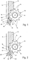
- Fig. 1 und 2
- jeweils ausschnittweise einen Häcksler in zwei unterschiedlichen Drehstellungen von Schneidwerkzeug und Gegenwerkzeug.
- 1 and 2
- A chopper in sections in two different rotary positions of cutting tool and counter tool.
Von dem Häcksler oder Zerkleinerer ist in Fig. 1 und 2 ausschnittweise nur sein unterer Bereich dargestellt, in welchem ein walzenförmiges Schneidwerkzeug 10 im unteren Ausgangsquerschnitt eines Beschickungsschachtes angeordnet ist, von dem nur die linke Seitenwand dargestellt ist, die eine Anlagewand 11 für das zu zerkleinernde Werkstück oder Häckselgut 12 bildet. Gegen diese Anlagewand 11 wird das Häckselgut 12 angedrückt, wenn das Schneidwerkzeug in dieses eindringt. Das rotierende Schneidwerkzeug 10 weist über seinen Umfang gleichmäßig verteilt und wechselweise aufeinanderfolgend Schneidzähne 13 und Zahnlücken 14 auf, die sich über die gesamte axiale Länge des Schneidwerkzeugs 10 erstrecken. Das Schneidwerkzeug 10 mit seiner in die Tiefe des Zeichenblatts verlaufenden Drehachse 15 ist relativ zu der Anlagewand 11 so angeordnet, daß die Anlagewand 11 etwa tangential zum Schneidwerkzeug 10 verläuft, und zwar bis zu dem mit 16 gekennzeichnenden Tangentenpunkt bzw. in die Tiefe der Zeichenebene verlaufenden Tangentenlinie. Von da ab verläuft die Anlagewand 11 bogenförmig gekrümmt noch bis zu einer in die Tiefe der Zeicheneben verlaufenden und mit 17 gekennzeichneten Linie, die sich parallel zu der Drehachse 15 erstreckt. Der Kreisradius dieser bogenförmigen Krümmung ist geringfügig größer als der Radius des Drehkreises der Schneidzahnspitzen und hat den gleichen Krümmungsmittelpunkt.1 and 2, only its lower area is shown in sections, in which a roller-
Zum Festhalten des Häckselgutes gegenüber dem Schneidwerkzeug 10, zum Zerkleinern und zum Ausräumen des in den Zahnlücken 17 sich nach Durchgang durch das Schneidwerkzeug 10 absetzenden zerspanten Materials ist ein Gegenwerkzeug 20 vorgesehen, das um eine parallel zur Drehachse 15 des Schneidwerkzeugs 10 sich erstreckende und zu dieser radial versetzt angeordnete Drehachse 19 drehbar gelagert und zur Rotation angetrieben ist. Die Drehrichtung des Gegenwerkzeugs 20 ist dabei der Drehrichtung des Schneidwerkzeuges 10 entgegengesetzt, und die Drehgeschwindigkeit des Gegenwerkzeugs 20 steht in einem festen Verhältnis zur Drehgeschwindigkeit des Schneidwerkzeugs 10. Das Verhältnis ist von der konstruktiven Ausführung des Gegenwerkzeugs 20 und des Schneidwerkzeugs 10 abhängig und nachstehend noch näher erläutert.A
Das Gegenwerkzeug 20 weist zwei auskragende armartige Gegenschneiden 21,22 auf, die am Gegenwerkzeug 20 zueinander diametral angeordnet sind und sich über die gesamte Axiallänge des Schneidwerkzeugs 10 bzw. des Gegenwerkzeugs 20 erstrecken und so ausgebildet sind, daß sie aufeinanderfolgend in aufeinanderfolgenden Zahnlücken 14 des Schneidwerkzeugs 10 eindrehen, wobei die Gegenschneidenspitzen jeweils an der Schneidzahnspitze aufeinanderfolgender Schneidzähne 13 in die dem jeweiligen Schneidzahn 13 in Drehrichtung vorausgehende Zahnlücke 14 eindrehen und darin in etwa an der Zahnlückenkontur entlanggleiten. Die in Drehrichtung vordere Begrenzungsfläche der Gegenschneiden 21,22 weist jeweils eine etwa bogenförmige und die in Drehrichtung hintere Begrenzungsfläche der Gegenschneide 21,22 jeweils eine etwa ebene, tangentiale verlaufende Kontur auf. Die Gegenschneidenspitzen sind in Drehrichtung gesehen zahnförmig ausgebildet, wobei die Zahnform ähnlich der der Schneidzähne 13 gestaltet ist.The
Die Drehgeschwindigkeit des Gegenwerkzeugs 20 mit den beiden Gegenschneiden 21,22 ist z/2 mal größer als die des Schneidwerkzeugs 10, wobei z die Anzahl der Schneidzähne 13 ist. Im vorliegenden Ausführungsbeispiel weist das Schneidwerkzeug 10 zehn Schneidzähne 13 auf, so daß die Drehgeschwindigkeit des Gegenwerkzeugs 20 fünfmal so groß ist wie die des Schneidwerkzeugs 10. Der Antrieb für das Gegenwerkzeug 20 wird dabei zweckmäßigerweise über ein Übersetzungsgetriebe mit einer Übersetzung von 5:1 von dem Antrieb für das Schneidwerkzeug 10 abgeleitet. Das Gegenwerkzeug 20 kann auch mit nur einer Gegenschneide oder auch drei oder vier Gegenschneiden ausgenutzt werden. Seine Drehgeschwindigkeit ist dann z/n mal größer als die Drehgeschwindigkeit des Schneidwerkzeugs 10 zu bemessen, wobei n die Anzahl der Gegenschneiden ist. Bei der Rotation von Schneidwerkzeug 10 und Gegenwerkzeug 20 haben die Spitzen der Gegenschneiden 21 und 22 und die Spitzen der Schneidzähne 13 in der Linie 17 ihre größte Annäherung. Längs dieser Linie 17 endet auch, wie eingangs beschrieben, die Anlagewand 11.The speed of rotation of the
Zum Häckseln wird das in dem Beschickungsschacht eingeworfene Häckselgut 12 von den Vorderflanken der Schneidzähne 13 erfaßt und eingezogen. Dabei wird das Häckselgut 12 gegen die Anlagewand 11 angepreßt, die dementsprechend auch als Zuführwand fungiert. Gleichzeitig wird das Häckselgut 12 in zuverlässiger Anlage an der Anlagewand 11 gehalten. Dieser Niederhalteeffekt verhindert Schlaglärm und erleichtert das Durchtrennen des Häckselguts 12 im Bereich der Linie 17 in Verbindung mit dem Gegenwerkzeug 20. Die Zahnlücken 14, in denen das abgeschnittene Material 121,122 beim Passieren der Linie 17 aufgenommen wird, werden mittels der Gegenschneiden 21 und 22 des auch als Räumers fungierenden Gegenwerkzeugs 20 ausgeräumt und freigehalten. Wie im Vergleich der Fig. 1 und 2 zu erkennen ist, taucht nach Abtrennen des Materials 121 vom Häckselgut 12 durch die Schneidzahnspitze und die Spitze der Gegenschneide 21 die Gegenschneide 21 in die in Drehrichtung des Schneidwerkzeugs 10 vorhergehende Zahnlücke 14 ein und schiebt das darin befindliche, von dem Häckselgut 12 getrennte Material 121 aus der Zahnlücke 14 aus (Fig. 2). Damit ist die Zahnlücke 14 ausgeräumt und kann beim erneuten Eintauchen in das Häckselgut 12 wieder Material aufnehmen. Als nächstes trennt die Gegenschneide 22 zusammen mit dem nachfolgenden Schneidzahn 13 das nächste Materialstück 122 ab und räumt es anschließend durch Eintauchen in die vorauseilende Zahnlücke 14 in gleicher Weise wie vorstehend beschrieben aus dieser aus. Das Gegenwerkzeug 20 wird durch das Schneidwerkzeug 10 ausräumend von Häckselgut befreit.For chopping, the chopped
Claims (9)
Applications Claiming Priority (2)
| Application Number | Priority Date | Filing Date | Title |
|---|---|---|---|
| DE4242640 | 1992-12-17 | ||
| DE4242640A DE4242640A1 (en) | 1992-12-17 | 1992-12-17 | Chopper |
Publications (2)
| Publication Number | Publication Date |
|---|---|
| EP0602408A1 true EP0602408A1 (en) | 1994-06-22 |
| EP0602408B1 EP0602408B1 (en) | 1997-04-02 |
Family
ID=6475549
Family Applications (1)
| Application Number | Title | Priority Date | Filing Date |
|---|---|---|---|
| EP93118708A Expired - Lifetime EP0602408B1 (en) | 1992-12-17 | 1993-11-22 | Shredder |
Country Status (3)
| Country | Link |
|---|---|
| US (1) | US5373998A (en) |
| EP (1) | EP0602408B1 (en) |
| DE (2) | DE4242640A1 (en) |
Families Citing this family (3)
| Publication number | Priority date | Publication date | Assignee | Title |
|---|---|---|---|---|
| DE4344738A1 (en) * | 1993-12-28 | 1995-06-29 | Bosch Gmbh Robert | Chopper |
| DE19518378C1 (en) * | 1995-05-23 | 1996-11-14 | Elektra Beckum Ag | Garden shredder for leaves and branches |
| CN115228570A (en) * | 2022-07-21 | 2022-10-25 | 董强 | Shredder with function of preventing materials from being wound |
Citations (2)
| Publication number | Priority date | Publication date | Assignee | Title |
|---|---|---|---|---|
| GB2059804A (en) * | 1979-10-16 | 1981-04-29 | Sant Andrea Novara Officine | Comminuting machine |
| EP0469380A1 (en) * | 1990-07-28 | 1992-02-05 | Lescha Maschinenfabrik GmbH & Co. KG | Chopper |
Family Cites Families (5)
| Publication number | Priority date | Publication date | Assignee | Title |
|---|---|---|---|---|
| US98757A (en) * | 1870-01-11 | Improvement in cider-mills | ||
| US1032132A (en) * | 1911-10-20 | 1912-07-09 | Charles Gormley | Fertilizer-distributer. |
| US4410144A (en) * | 1981-02-26 | 1983-10-18 | General Steel Industries, Inc. | Synchronously coordinated counterrotated crusher roll teeth system |
| US4401279A (en) * | 1981-08-27 | 1983-08-30 | General Steel Industries, Inc. | Synchronously counter-rotating intermeshing differential speed crusher roll assembly |
| JP3188909B2 (en) * | 1991-07-17 | 2001-07-16 | 松爾 中込 | 2-axis crusher |
-
1992
- 1992-12-17 DE DE4242640A patent/DE4242640A1/en not_active Withdrawn
-
1993
- 1993-11-22 DE DE59306028T patent/DE59306028D1/en not_active Expired - Fee Related
- 1993-11-22 EP EP93118708A patent/EP0602408B1/en not_active Expired - Lifetime
- 1993-12-15 US US08/167,770 patent/US5373998A/en not_active Expired - Fee Related
Patent Citations (3)
| Publication number | Priority date | Publication date | Assignee | Title |
|---|---|---|---|---|
| GB2059804A (en) * | 1979-10-16 | 1981-04-29 | Sant Andrea Novara Officine | Comminuting machine |
| EP0469380A1 (en) * | 1990-07-28 | 1992-02-05 | Lescha Maschinenfabrik GmbH & Co. KG | Chopper |
| DE4024060C2 (en) * | 1990-07-28 | 1992-08-20 | Lescha Maschinenfabrik Gmbh & Co Kg, 8900 Augsburg, De |
Also Published As
| Publication number | Publication date |
|---|---|
| EP0602408B1 (en) | 1997-04-02 |
| DE59306028D1 (en) | 1997-05-07 |
| DE4242640A1 (en) | 1994-06-23 |
| US5373998A (en) | 1994-12-20 |
Similar Documents
| Publication | Publication Date | Title |
|---|---|---|
| DE2649305C3 (en) | Perforated disc for a meat grinder | |
| DE4024060C2 (en) | ||
| EP1687091B1 (en) | Device for comminuting empty containers | |
| DE3305063A1 (en) | WASTE CRUSHING DEVICE | |
| EP2070666A1 (en) | String cutting device | |
| DE2701897A1 (en) | DEVICE FOR CRUSHING DIFFERENT TYPES OF WASTE, IN PARTICULAR INDUSTRIAL WASTE AND BARRIER | |
| EP0387868B1 (en) | Shredding apparatus for waste wood | |
| DE3221431A1 (en) | DEVICE FOR CRUSHING PLASTIC PARTS, IN PARTICULAR CHASSES | |
| CH659405A5 (en) | WASTE CRUSHING DEVICE. | |
| DE2243467A1 (en) | DEVICE FOR OPENING ENVELOPES AND THE LIKE | |
| EP0602408B1 (en) | Shredder | |
| WO1998028079A1 (en) | Meat chopper | |
| DE102019108306A1 (en) | Cutting mill for cutting samples | |
| DE4444977C2 (en) | Shredding plant | |
| DE4427700C2 (en) | Device for shredding garden waste | |
| DE2049124C3 (en) | Machine for shredding bulky goods | |
| EP0847805A1 (en) | Cutting tool for screw conveyor device | |
| DE2618254A1 (en) | Wood and paper refuse cutting drum - has discs mounted along shaft, each with projecting cutter blades | |
| EP0089571B1 (en) | Wood disintegrating device | |
| DE3434303C2 (en) | Device for shredding waste | |
| EP0505701A1 (en) | Garden waste shredder with a blade housing containing rotating, powered flat blades | |
| DE10117154A1 (en) | chopper | |
| EP2564930B1 (en) | Shredder | |
| DE4400312A1 (en) | Meat mincer | |
| DE3104586A1 (en) | Device for comminuting waste |
Legal Events
| Date | Code | Title | Description |
|---|---|---|---|
| PUAI | Public reference made under article 153(3) epc to a published international application that has entered the european phase |
Free format text: ORIGINAL CODE: 0009012 |
|
| AK | Designated contracting states |
Kind code of ref document: A1 Designated state(s): CH DE FR GB IT LI |
|
| 17P | Request for examination filed |
Effective date: 19941222 |
|
| GRAG | Despatch of communication of intention to grant |
Free format text: ORIGINAL CODE: EPIDOS AGRA |
|
| GRAH | Despatch of communication of intention to grant a patent |
Free format text: ORIGINAL CODE: EPIDOS IGRA |
|
| 17Q | First examination report despatched |
Effective date: 19960912 |
|
| GRAH | Despatch of communication of intention to grant a patent |
Free format text: ORIGINAL CODE: EPIDOS IGRA |
|
| GRAA | (expected) grant |
Free format text: ORIGINAL CODE: 0009210 |
|
| AK | Designated contracting states |
Kind code of ref document: B1 Designated state(s): CH DE FR GB IT LI |
|
| REG | Reference to a national code |
Ref country code: CH Ref legal event code: NV Representative=s name: SCINTILLA AG, DIREKTION Ref country code: CH Ref legal event code: EP |
|
| ET | Fr: translation filed | ||
| REF | Corresponds to: |
Ref document number: 59306028 Country of ref document: DE Date of ref document: 19970507 |
|
| GBT | Gb: translation of ep patent filed (gb section 77(6)(a)/1977) |
Effective date: 19970605 |
|
| PLBE | No opposition filed within time limit |
Free format text: ORIGINAL CODE: 0009261 |
|
| STAA | Information on the status of an ep patent application or granted ep patent |
Free format text: STATUS: NO OPPOSITION FILED WITHIN TIME LIMIT |
|
| 26N | No opposition filed | ||
| PGFP | Annual fee paid to national office [announced via postgrant information from national office to epo] |
Ref country code: CH Payment date: 19991125 Year of fee payment: 7 |
|
| PG25 | Lapsed in a contracting state [announced via postgrant information from national office to epo] |
Ref country code: LI Free format text: LAPSE BECAUSE OF NON-PAYMENT OF DUE FEES Effective date: 20001130 Ref country code: CH Free format text: LAPSE BECAUSE OF NON-PAYMENT OF DUE FEES Effective date: 20001130 |
|
| REG | Reference to a national code |
Ref country code: CH Ref legal event code: PL |
|
| REG | Reference to a national code |
Ref country code: GB Ref legal event code: IF02 |
|
| PG25 | Lapsed in a contracting state [announced via postgrant information from national office to epo] |
Ref country code: IT Free format text: LAPSE BECAUSE OF NON-PAYMENT OF DUE FEES;WARNING: LAPSES OF ITALIAN PATENTS WITH EFFECTIVE DATE BEFORE 2007 MAY HAVE OCCURRED AT ANY TIME BEFORE 2007. THE CORRECT EFFECTIVE DATE MAY BE DIFFERENT FROM THE ONE RECORDED. Effective date: 20051122 |
|
| PGFP | Annual fee paid to national office [announced via postgrant information from national office to epo] |
Ref country code: FR Payment date: 20071120 Year of fee payment: 15 |
|
| PGFP | Annual fee paid to national office [announced via postgrant information from national office to epo] |
Ref country code: DE Payment date: 20090126 Year of fee payment: 16 |
|
| PGFP | Annual fee paid to national office [announced via postgrant information from national office to epo] |
Ref country code: GB Payment date: 20081121 Year of fee payment: 16 |
|
| REG | Reference to a national code |
Ref country code: FR Ref legal event code: ST Effective date: 20090731 |
|
| GBPC | Gb: european patent ceased through non-payment of renewal fee |
Effective date: 20091122 |
|
| PG25 | Lapsed in a contracting state [announced via postgrant information from national office to epo] |
Ref country code: DE Free format text: LAPSE BECAUSE OF NON-PAYMENT OF DUE FEES Effective date: 20100601 |
|
| PG25 | Lapsed in a contracting state [announced via postgrant information from national office to epo] |
Ref country code: GB Free format text: LAPSE BECAUSE OF NON-PAYMENT OF DUE FEES Effective date: 20091122 |
|
| PG25 | Lapsed in a contracting state [announced via postgrant information from national office to epo] |
Ref country code: FR Free format text: LAPSE BECAUSE OF NON-PAYMENT OF DUE FEES Effective date: 20081130 |