EP0601966A2 - Method of treating secondary raw materials from waste and installation for carrying out the method - Google Patents
Method of treating secondary raw materials from waste and installation for carrying out the method Download PDFInfo
- Publication number
- EP0601966A2 EP0601966A2 EP19930810703 EP93810703A EP0601966A2 EP 0601966 A2 EP0601966 A2 EP 0601966A2 EP 19930810703 EP19930810703 EP 19930810703 EP 93810703 A EP93810703 A EP 93810703A EP 0601966 A2 EP0601966 A2 EP 0601966A2
- Authority
- EP
- European Patent Office
- Prior art keywords
- mixture
- dehumidification
- closed
- materials
- plant
- Prior art date
- Legal status (The legal status is an assumption and is not a legal conclusion. Google has not performed a legal analysis and makes no representation as to the accuracy of the status listed.)
- Granted
Links
Images
Classifications
-
- B—PERFORMING OPERATIONS; TRANSPORTING
- B09—DISPOSAL OF SOLID WASTE; RECLAMATION OF CONTAMINATED SOIL
- B09B—DISPOSAL OF SOLID WASTE
- B09B3/00—Destroying solid waste or transforming solid waste into something useful or harmless
-
- B—PERFORMING OPERATIONS; TRANSPORTING
- B03—SEPARATION OF SOLID MATERIALS USING LIQUIDS OR USING PNEUMATIC TABLES OR JIGS; MAGNETIC OR ELECTROSTATIC SEPARATION OF SOLID MATERIALS FROM SOLID MATERIALS OR FLUIDS; SEPARATION BY HIGH-VOLTAGE ELECTRIC FIELDS
- B03B—SEPARATING SOLID MATERIALS USING LIQUIDS OR USING PNEUMATIC TABLES OR JIGS
- B03B9/00—General arrangement of separating plant, e.g. flow sheets
- B03B9/06—General arrangement of separating plant, e.g. flow sheets specially adapted for refuse
-
- F—MECHANICAL ENGINEERING; LIGHTING; HEATING; WEAPONS; BLASTING
- F26—DRYING
- F26B—DRYING SOLID MATERIALS OR OBJECTS BY REMOVING LIQUID THEREFROM
- F26B21/00—Arrangements or duct systems, e.g. in combination with pallet boxes, for supplying and controlling air or gases for drying solid materials or objects
- F26B21/06—Controlling, e.g. regulating, parameters of gas supply
- F26B21/10—Temperature; Pressure
-
- F—MECHANICAL ENGINEERING; LIGHTING; HEATING; WEAPONS; BLASTING
- F26—DRYING
- F26B—DRYING SOLID MATERIALS OR OBJECTS BY REMOVING LIQUID THEREFROM
- F26B25/00—Details of general application not covered by group F26B21/00 or F26B23/00
- F26B25/06—Chambers, containers, or receptacles
-
- Y—GENERAL TAGGING OF NEW TECHNOLOGICAL DEVELOPMENTS; GENERAL TAGGING OF CROSS-SECTIONAL TECHNOLOGIES SPANNING OVER SEVERAL SECTIONS OF THE IPC; TECHNICAL SUBJECTS COVERED BY FORMER USPC CROSS-REFERENCE ART COLLECTIONS [XRACs] AND DIGESTS
- Y02—TECHNOLOGIES OR APPLICATIONS FOR MITIGATION OR ADAPTATION AGAINST CLIMATE CHANGE
- Y02W—CLIMATE CHANGE MITIGATION TECHNOLOGIES RELATED TO WASTEWATER TREATMENT OR WASTE MANAGEMENT
- Y02W30/00—Technologies for solid waste management
- Y02W30/50—Reuse, recycling or recovery technologies
- Y02W30/52—Mechanical processing of waste for the recovery of materials, e.g. crushing, shredding, separation or disassembly
-
- Y—GENERAL TAGGING OF NEW TECHNOLOGICAL DEVELOPMENTS; GENERAL TAGGING OF CROSS-SECTIONAL TECHNOLOGIES SPANNING OVER SEVERAL SECTIONS OF THE IPC; TECHNICAL SUBJECTS COVERED BY FORMER USPC CROSS-REFERENCE ART COLLECTIONS [XRACs] AND DIGESTS
- Y10—TECHNICAL SUBJECTS COVERED BY FORMER USPC
- Y10S—TECHNICAL SUBJECTS COVERED BY FORMER USPC CROSS-REFERENCE ART COLLECTIONS [XRACs] AND DIGESTS
- Y10S241/00—Solid material comminution or disintegration
- Y10S241/38—Solid waste disposal
Definitions
- the invention relates to a method for processing secondary raw materials from waste, i.e. from a non-uniform mixture of recyclable materials that have not been used, the solid parts of the mixed recyclable materials being crushed and separated into pure fractions and subjected to a dehumidification process.
- a major problem is the control over the whereabouts of the so-called pollutants during the processing process.
- pollutants can occur as pollutants if they volatilize or become detached from their original relationship with other inorganic substances by gasification and attach to the organic substances present in the same batch , from which they are difficult to separate properly.
- reusable organic materials are reused, heavy metal compounds associated with them can get into an environment in which they have a harmful effect, e.g. if they enter the food cycle with a secondary raw material used as a fertilizer.
- the aim of the invention is to provide an improved preparation process of the type mentioned at the outset, in which the dehumidification is carried out in such a way that any potential pollutants are not released but are left in their original state.
- the dehumidification process extends continuously to all areas of the treatment process.
- the dehumidification zone is increased enormously and thus the duration of exposure of the drying air to the material is considerably extended compared to a separate drying station.
- the dehumidification can be carried out with a relatively low temperature of the drying air, so that a rearrangement of potential pollutants is avoided.
- the additional residence time of the material in a separate drying station according to the known method is eliminated. This shortens the entire throughput time of the material through the entire preparation process including dehumidification by up to 25%.
- the processing process in its entirety includes all those process stages which ultimately lead to separate fractions of recyclable materials, the various fractions in the final state having a uniform piece size suitable for their previous separation and one suitable for further use Have moisture levels. Any further processing of these fractions, referred to as confectioning (e.g. repeated comminution, addition of aggregates, packaging of secondary raw materials) is not part of the processing process in the aforementioned sense.
- the entire preparation process preferably takes place in an atmosphere closed to the outside with an air circulation which causes dehumidification, it being expedient to keep the closed atmosphere at a negative pressure.
- an air circulation which causes dehumidification, it being expedient to keep the closed atmosphere at a negative pressure.
- the circulating air can be reprocessed, that is to say dehumidified and cleaned, with heating of the air to higher temperatures being permitted without any problems during the air treatment, because that of the closed Air taken from the atmosphere does not contain any heavy metal compounds, which could volatilize under certain circumstances and thereby escape further control.
- the method according to the invention therefore has the further advantage that dehumidification can also be used to achieve deodorization and, if necessary, sterilization of the material without exposing the material itself to an excessively high temperature with respect to the heavy metal compounds.
- Effective and easily controllable dehumidification of the material can be achieved by cooling the mixture of recyclable materials in the closed atmosphere at the beginning of the processing process and heating it again at the end of the process.
- the temperature in the closed atmosphere is a few degrees, e.g. 5 ° C, above the freezing point of water and at the end of it at most 100 ° C.
- a low initial temperature guarantees that the temperature of the processed material cannot reach a level that exceeds the set limit during the preparation process.
- this prevents the material from overheating under the influence of the waste heat from the machines involved in the processing process.
- the increased final temperature prevents the formation of condensation when the material escapes into the free atmosphere.
- the invention also relates to a plant for carrying out the method according to the invention, which is characterized in that the mechanical and apparatus devices for processing and transporting the mixture of valuable substances follow one another on the way of the processing process. outside are hermetically sealed.
- the mechanical and apparatus equipment for processing the mixture of valuable materials include, on the one hand, crushing machines (shredders, rotor shears, mills and the like) and, on the other hand, separating devices (sieves, cyclones and other separators), and conveyor belts (heavy materials) and pipelines are preferred for transporting the material. Light and suspended materials) are used.
- crushing machines shredders, rotor shears, mills and the like
- separating devices sieves, cyclones and other separators
- conveyor belts heavy materials
- Light and suspended materials are used.
- the facilities mentioned, which are optionally used depending on the type of material mixture to be processed and the type of desired end products, are known per se and are not explained in more detail here.
- a preferred embodiment of the system according to the invention consists in the closed space being divided into several sections which are connected to one another by locks, in particular rotor locks.
- This solution makes it possible to shut off the sections of the room individually in the event of a malfunction in the preparation process and thus localize harmful effects.
- Another advantage of this division of space is that the dehumidification process is regulated in sections and in particular the air temperature in each section of the room can be adjusted to the level of moisture to be achieved. In this way, it is also easier to control the temperature curve along the entire dehumidification zone, in particular to keep the air temperature relatively low at the beginning of the treatment process and to increase it to the desired extent in the end phase.
- a particularly expedient embodiment of the system according to the invention results if the enclosed space is designed as a tunnel.
- the tunnel tube which is primarily constructed of steel, should have as small a volume as possible in order to keep the amount of air required for the dehumidification per unit of time within limits.
- Such a system can not only be accommodated in a building, but can also be designed to be mobile, for example by arranging it on a train comprising several carriages, for example railway carriages.
- Each car can have at least one tunnel section.
- a lock can be arranged at one end of each car and a movable tunnel connection with a detachable connection to the next following tunnel section can be arranged at the other end thereof.
- Mobile processing plants can be useful for emergency operations in areas with temporarily excessive waste.
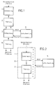
- the mixture of valuable materials i.e. the raw waste, crushed in a first process stage 1 and separated into pure recyclable material fractions in a second process stage 2. These are dehumidified together in a third process stage 3 and then again separated from one another in a fourth process stage 4. The air required in the third process stage 3 is processed in a separate process stage 5.
- the dehumidification process extends continuously to all areas of the treatment process. It therefore includes process stages 1 and 2, in which the mixture of valuable materials is comminuted and separated into fractions, while the dehumidification of the material concentrated in a separate process stage 3 1 is omitted.
- the entire preparation process which in the present example comprises the two process stages 1 and 2, takes place in an atmosphere, which is indicated by the marking 6 and is closed to the outside, with an air circulation which dehumidifies the material.
- the processing of the circulating air is again carried out in a separate process stage 5.
- process stages 1 and 2 are generally not completely separated from one another in the manner specified; rather, shredding and separation processes usually take place in an alternating sequence.
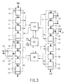
- the mechanical devices for processing and transporting the mixture of valuable materials are located in a space that is hermetically sealed from the outside, which in the present example is designed as a tunnel.
- This tunnel is divided into four tunnel sections T1 to T4, which are functionally arranged one behind the other and are connected to one another by locks 10, in particular rotor locks.
- Each tunnel section contains a plurality of processing stations, belt conveyors 11 being provided as conveying means for transferring the material from one processing station to the next in the first three tunnel sections T1, T2 and T3 for the still mixed heavy and light material, while that is left in the last tunnel section T4 permanent light material is mainly conveyed pneumatically.
- the size and composition of the shredding and separation stations mentioned below are to be considered as examples. Depending on the application, some of the stations mentioned may be required multiple times or additional stations, while on the other hand certain stations may be omitted.
- the tunnel section T1 there is a receiving station 14, in which the raw waste delivered through a lockable gate 13 is received and weighed.
- the raw waste then passes into a waste bunker 15, from there into a shredder 16 and finally onto a viewing belt 17.
- a continuous control sensors already localizing dangerous or otherwise unsuitable material for further processing and their removal in to lead the way.
- the material passes through a rotor shear 18, a magnetic separator 19, a further rotor shear 20 and a flex mill 21.
- the stations 16, 18, 20 and 21 gradually shred the material passing through to a maximum grain size of, for example, 20 mm.
- the ferrous metals (FE) accumulating on the magnetic separator 19 are removed from the tunnel section T2 by means of a scrap belt 22 through a lock 23.
- a screening station 24 from which sand and dust (S) are separated by means of filters and fans.
- a cyclone separator 25 serves the same purpose.
- station 26 a so-called hard material separator, the material is converted into hard materials (HS), which are predominantly heavy, inorganic substances, and in predominantly organic, flake-like light materials (LS) separated.
- the hard materials (HS) leave the processing plant in the region of the tunnel section T3 through a lock 27.
- the light materials (LS) finally reach the last tunnel section T4, which comprises a cyclone separator 29, a hammer mill 30 and a further cyclone separator 31, via a cyclone separator 28.
- the light materials (LS) are removed from the processing plant through a lock 32 which closes the tunnel section T4.
- the exhaust air from the tunnel sections T1 to T4 and also the direct exhaust air from the stations 14, 15, 16, 28, 29 and 31 are fed to one of the two air cleaners LR, which work together with a dehumidifier LE and from which the cleaned and dehumidified air again is fed to the individual tunnel sections T1 to T4.
- fresh air FL arrives via the dehumidifier LE on the circulation path of the circulating air used to dehumidify the material in the tunnel sections T1 to T4.
- the water in large quantities in the dehumidifier LE can be reused for suitable purposes.
Abstract
Description
Die Erfindung betrifft ein Verfahren zur Aufbereitung von Sekundärrohstoffen aus Abfällen, d.h. aus einem uneinheitlichen Gemisch ausser Gebrauch gelangter Wertstoffe, wobei die festen Anteile der vermischten Wertstoffe zerkleinert und in artreine Fraktionen getrennt sowie einem Entfeuchtungsprozess unterworfen werden.The invention relates to a method for processing secondary raw materials from waste, i.e. from a non-uniform mixture of recyclable materials that have not been used, the solid parts of the mixed recyclable materials being crushed and separated into pure fractions and subjected to a dehumidification process.
Als Wertstoffe werden die in Abfällen jeglicher Art und Herkunft enthaltenen, grundsätzlich wiederverwendbaren Stoffe bezeichnet. Das Bestreben geht dahin, den Abfall möglichst restlos auszuwerten bzw. dessen Wertstoffe möglichst vollständig zurückzugewinnen und zu Sekundärrohstoffen aufzubereiten, welche in den Produktionsprozess zurückgeführt werden können. Damit sollen die sonst übliche Vernichtung oder ungenützte Ablagerung des Abfalls bzw. der darin vorhandenen Wertstoffe und die mit solchen Verfahren verbundenen Umweltbelastungen weitgehend vermieden werden.Materials that are basically reusable in waste of any kind and origin are referred to as valuable materials. The aim is to evaluate the waste as completely as possible or to recover its valuable materials as completely as possible and to process them into secondary raw materials that can be returned to the production process. This is to largely avoid the otherwise usual destruction or unused deposition of the waste or the valuable materials contained therein and the environmental pollution associated with such processes.
Industriell betriebene Aufbereitungsanlagen müssen gewährleisten, dass die aufbereiteten Wertstoff-Fraktionen artrein sind und den gesetzlichen Schadstoffgrenzen entsprechen. Voraussetzung dazu ist, dass der Aufbereitungsprozess in einer Anlage erfolgt, welche sauber trennt und keine Umverteilung oder Anreicherung von Schadstoffanteilen innerhalb der Wertstoffkomponenten zulässt.Industrially operated processing plants must ensure that the recycled recyclable material fractions are pure and comply with the legal pollutant limits. The prerequisite for this is that the preparation process takes place in a plant, which separates cleanly and does not allow redistribution or enrichment of pollutant components within the recyclable components.
Ein wesentliches Problem stellt die Kontrolle über den Verbleib der sogenannten Schadstoffe während des Aufbereitungsprozesses dar. Beispielsweise können Schwermetallverbindungen als Schadstoffe auftreten, wenn sie sich verflüchtigen bzw. durch Vergasen aus ihrem ursprünglichen Zusammenhang mit anderen anorganischen Stoffen lösen und den im gleichen Gemenge vorhandenen organischen Stoffen anlagern, von denen sie dann nur schwer wieder einwandfrei zu trennen sind. Bei der Wiederverwendung so aufbereiteter organischer Wertstoffe können mit diesen verbundene Schwermetallverbindungen in eine Umgebung gelangen, in der sie sich schädlich auswirken, z.B. wenn sie mit einem als Düngemittel verwendeten Sekundärrohstoff in den Nahrungskreislauf gelangen.A major problem is the control over the whereabouts of the so-called pollutants during the processing process. For example, heavy metal compounds can occur as pollutants if they volatilize or become detached from their original relationship with other inorganic substances by gasification and attach to the organic substances present in the same batch , from which they are difficult to separate properly. When reusable organic materials are reused, heavy metal compounds associated with them can get into an environment in which they have a harmful effect, e.g. if they enter the food cycle with a secondary raw material used as a fertilizer.
Die Gefahr einer Lostrennung potentieller Schadstoffe durch Vergasen besteht insbesondere beim Entfeuchtungsprozess, wenn für das Entfeuchten bzw. Trocknen Arbeitstemperaturen von weit über 100°C angewandt werden, wie das oft der Fall ist. Bekanntlich gibt es aber giftige Schwermetallverbindungen, insbesondere Cd- und Hg-Verbindungen, welche zum Teil bereits bei etwa 115°C zu verdampfen beginnen.There is a risk of separation of potential pollutants by gasification, especially in the dehumidification process, if working temperatures of well over 100 ° C are used for dehumidification or drying, as is often the case. However, as is known, there are toxic heavy metal compounds, in particular Cd and Hg compounds, some of which already start to evaporate at around 115 ° C.
In bekannten Aufbereitungsanlagen (z.B. nach der CH-PS 650 172) ist für das Entfeuchten der Wertstoffe eine separate Trocknungsstation vorhanden, in welcher sämtliche Wertstoff-Fraktionen vor ihrer endgültigen Trennung und einer allfälligen weiteren Zerkleinerung gemeinsam mit trockener Luft behandelt werden. Meistens werden dazu hohe Lufttemperaturen angewandt, um eine möglichst kurze Verweilzeit des Materials in der Trocknungsstation zu erreichen. Zudem lässt sich auf diese Weise auch eine Sterilisierung des Materials erzielen. Bei diesem Entfeuchtungsverfahren wird aber das Material so stark erhitzt, dass eine Umlagerung der Schadstoffe im erwähnten Sinne praktisch kaum zu vermeiden ist.In known processing plants (for example according to CH-PS 650 172) there is a separate drying station for dehumidifying the valuable materials, in which all valuable material fractions are present their final separation and any further comminution are treated together with dry air. Mostly, high air temperatures are used to achieve the shortest possible residence time of the material in the drying station. The material can also be sterilized in this way. With this dehumidification process, however, the material is heated to such an extent that a rearrangement of the pollutants in the aforementioned sense can practically be avoided.
Das Ziel der Erfindung ist es, ein verbessertes Aufbereitungsverfahren der eingangs genannten Art anzugeben, bei welchem die Entfeuchtung so vorgenommen wird, dass allfällige potentielle Schadstoffe nicht freigesetzt, sondern in ihrer ursprünglichen Zustandsform belassen werden.The aim of the invention is to provide an improved preparation process of the type mentioned at the outset, in which the dehumidification is carried out in such a way that any potential pollutants are not released but are left in their original state.
Dieses Ziel lässt sich erreichen, wenn erfindungsgemäss der Entfeuchtungsprozess sich durchlaufend auf alle Bereiche des Aufbereitungsprozesses erstreckt. Durch den Einbezug des Entfeuchtungsprozesses in den gesamten Aufbereitungsprozess wird die Entfeuchtungszone enorm vergrössert und damit die Einwirkungsdauer der Trocknungsluft auf das Material im Vergleich zu einer separaten Trocknungsstation erheblich verlängert. Infolgedessen kann die Entfeuchtung mit einer verhältnismässig niedrigen Temperatur der Trocknungsluft vorgenommen werden, so dass eine Umlagerung potentieller Schadstoffe vermieden wird. Zudem entfällt die zusätzliche Verweilzeit des Materials in einer separaten Trocknungsstation gemäss dem bekannten Verfahren. Dadurch verkürzt sich die gesamte Durchlaufzeit des Materials durch den gesamten Aufbereitungsprozess einschliesslich Entfeuchtung um bis zu 25%.This goal can be achieved if, according to the invention, the dehumidification process extends continuously to all areas of the treatment process. By integrating the dehumidification process into the entire preparation process, the dehumidification zone is increased enormously and thus the duration of exposure of the drying air to the material is considerably extended compared to a separate drying station. As a result, the dehumidification can be carried out with a relatively low temperature of the drying air, so that a rearrangement of potential pollutants is avoided. In addition, the additional residence time of the material in a separate drying station according to the known method is eliminated. This shortens the entire throughput time of the material through the entire preparation process including dehumidification by up to 25%.
Der Aufbereitungsprozess umfasst in seiner Gesamtheit, so wie sie hier verstanden werden soll, alle jene Verfahrensstufen, welche schliesslich zu artrein getrennten Wertstoff-Fraktionen führen, wobei die verschiedenen Fraktionen im Endzustand eine einheitliche, für deren vorherige Trennung geeignete Stückgrösse sowie einen für die Weiterverwendung geeigneten Feuchtigkeitsgrad aufweisen. Eine allfällige weitere, als Konfektionierung bezeichnete Verarbeitung dieser Fraktionen (z.B. nochmalige Zerkleinerung, Beimengung von Zuschlägen, Verpackung der Sekundärrohstoffe) gehört nicht zum Aufbereitungsprozess im vorgenannten Sinne.The processing process in its entirety, as it is to be understood here, includes all those process stages which ultimately lead to separate fractions of recyclable materials, the various fractions in the final state having a uniform piece size suitable for their previous separation and one suitable for further use Have moisture levels. Any further processing of these fractions, referred to as confectioning (e.g. repeated comminution, addition of aggregates, packaging of secondary raw materials) is not part of the processing process in the aforementioned sense.
Vorzugsweise findet der gesamte Aufbereitungsprozess in einer nach aussen abgeschlossenen Atmosphäre mit einer die Entfeuchtung bewirkenden Luftzirkulation statt, wobei es zweckmässig ist, die abgeschlossene Atmosphäre auf Unterdruck zu halten. Erfahrungsgemäss verschwinden mit der Entfeuchtung des Materials auch geruchsbildende und/oder biologisch bedenkliche Bakterien, welche durch den zirkulierenden Luftstrom nach aussen abgeführt werden. In einem ausserhalb dieser abgeschlossenen Atmosphäre stattfindenden Verfahrensschritt kann die zirkulierende Luft wieder aufbereitet, d.h. entfeuchtet und gereinigt werden, wobei während der Luftaufbereitung allenfalls eine Erwärmung der Luft auf höhere Temperaturen problemlos zulässig ist, weil die der abgeschlossenen Atmosphäre entnommene Luft voraussetzungsgemäss keine Schwermetallverbindungen enthält, welche sich unter Umständen verflüchtigen und dadurch der weiteren Kontrolle entziehen könnten. Das erfindungsgemässe Verfahren hat also in dieser besonderen Ausführungsform den weiteren Vorteil, dass sich auf diese Weise mit der Entfeuchtung auch eine Desodorierung und allenfalls Sterilisierung des Materials erreichen lässt, ohne das Material selbst einer hinsichtlich der Schwermetallverbindungen überhöhten Temperatur auszusetzen.The entire preparation process preferably takes place in an atmosphere closed to the outside with an air circulation which causes dehumidification, it being expedient to keep the closed atmosphere at a negative pressure. Experience has shown that with the dehumidification of the material, odor-forming and / or biologically questionable bacteria disappear, which are discharged to the outside by the circulating air flow. In a process step taking place outside this closed atmosphere, the circulating air can be reprocessed, that is to say dehumidified and cleaned, with heating of the air to higher temperatures being permitted without any problems during the air treatment, because that of the closed Air taken from the atmosphere does not contain any heavy metal compounds, which could volatilize under certain circumstances and thereby escape further control. In this particular embodiment, the method according to the invention therefore has the further advantage that dehumidification can also be used to achieve deodorization and, if necessary, sterilization of the material without exposing the material itself to an excessively high temperature with respect to the heavy metal compounds.
Eine wirkungsvolle und gut regulierbare Entfeuchtung des Materials lässt sich dadurch erreichen, dass das in der abgeschlossenen Atmosphäre befindliche Wertstoffgemisch am Anfang des Aufbereitungsprozesses gekühlt und am Ende desselben wieder erwärmt wird. Vorzugsweise beträgt die Temperatur in der abgeschlossenen Atmosphäre am Anfang des Aufbereitungsprozesses wenige Grade, z.B. 5°C, über dem Gefrierpunkt von Wasser und am Ende desselben höchstens 100°C. Eine niedrige Anfangstemperatur biete Gewähr, dass die Temperatur des verarbeiteten Materials im Zuge des Aufbereitungsprozesses kein die gesetzte Grenze überschreitendes Mass erreichen kann.Effective and easily controllable dehumidification of the material can be achieved by cooling the mixture of recyclable materials in the closed atmosphere at the beginning of the processing process and heating it again at the end of the process. Preferably, the temperature in the closed atmosphere is a few degrees, e.g. 5 ° C, above the freezing point of water and at the end of it at most 100 ° C. A low initial temperature guarantees that the temperature of the processed material cannot reach a level that exceeds the set limit during the preparation process.
Insbesondere wird auf diese Weise eine Überhitzung des Materials unter dem Einfluss der Abwärme der am Aufbereitungsprozess beteiligten Maschinen verhindert. Andererseits wird durch die erhöhte Endtemperatür eine Kondenswasserbildung beim Austritt des Materials in die freie Atmosphäre vermieden.In particular, this prevents the material from overheating under the influence of the waste heat from the machines involved in the processing process. On the other hand, the increased final temperature prevents the formation of condensation when the material escapes into the free atmosphere.
Die Erfindung betrifft auch eine Anlage zur Durchführung des erfindungsgemässen Verfahrens, welche dadurch gekennzeichnet ist, dass sich die maschinellen und apparativen Einrichtungen für die Verarbeitung und den Transport des Wertstoffgemisches auf dem Weg des Aufbereitungsprozesses in einem nach. aussen hermetisch abgeschlossenen Raum befinden.The invention also relates to a plant for carrying out the method according to the invention, which is characterized in that the mechanical and apparatus devices for processing and transporting the mixture of valuable substances follow one another on the way of the processing process. outside are hermetically sealed.
Die maschinellen und apparativen Einrichtungen für die Verarbeitung des Wertstoffgemisches umfassen einerseits Zerkleinerungsmaschinen (Reisswolf, Rotorscheren, Mühlen und dgl.) und andererseits Trennvorrichtungen (Siebe, Zyklone und andere Abscheider), und für den Transport des Materials kommen vorzugsweise Förderbänder (Schwerstoffe) und Rohrleitungen (Leicht- und Schwebestoffe) zum Einsatz. Die erwähnten Einrichtungen, welche je nach der Art des zu verarbeitenden Wertstoffgemischs und der Art der gewünschten Endstoffe wahlweise eingesetzt werden, sind an sich bekannt und werden hier nicht näher erläutert.The mechanical and apparatus equipment for processing the mixture of valuable materials include, on the one hand, crushing machines (shredders, rotor shears, mills and the like) and, on the other hand, separating devices (sieves, cyclones and other separators), and conveyor belts (heavy materials) and pipelines are preferred for transporting the material. Light and suspended materials) are used. The facilities mentioned, which are optionally used depending on the type of material mixture to be processed and the type of desired end products, are known per se and are not explained in more detail here.
Eine bevorzugte Ausführungsform der erfindungsgemässen Anlage besteht darin, dass der abgeschlossene Raum in mehrere Abschnitte unterteilt ist, welche durch Schleusen, insbesondere Rotorschleusen, miteinander verbunden sind. Diese Lösung ermöglicht es, im Falle einer Störung des Aufbereitungsprozesses die Raumabschnitte einzeln abzusperren und damit schädliche Auswirkungen zu lokalisieren. Ein weiterer Vorteil dieser Raumaufteilung besteht darin, dass der Entfeuchtungsprozess abschnittweise geregelt und insbesondere die Lufttemperatur in jedem Raumabschnitt dem jeweils zu erreichenden Feuchtigkeitsgrad angepasst werden kann. Auf diese Weise ist es auch einfacher, den Temperaturverlauf längs der gesamten Entfeuchtungszone zu kontrollieren, insbesondere die Lufttemperatur am Anfang des Aufbereitungsprozesses verhältnismässig tief zu halten und in der Endphase desselben im gewünschten Masse zu erhöhen.A preferred embodiment of the system according to the invention consists in the closed space being divided into several sections which are connected to one another by locks, in particular rotor locks. This solution makes it possible to shut off the sections of the room individually in the event of a malfunction in the preparation process and thus localize harmful effects. Another advantage of this division of space is that the dehumidification process is regulated in sections and in particular the air temperature in each section of the room can be adjusted to the level of moisture to be achieved. In this way, it is also easier to control the temperature curve along the entire dehumidification zone, in particular to keep the air temperature relatively low at the beginning of the treatment process and to increase it to the desired extent in the end phase.
Eine besonders zweckmässige Ausführungsform der erfindungsgemässen Anlage ergibt sich, wenn der abgeschlossene Raum als Tunnel ausgebildet ist. Dabei soll die vornehmlich in Stahlbauweise errichtete Tunnelröhre ein möglichst kleines Volumen haben, um die pro Zeiteinheit benötigte Luftmenge für die Entfeuchtung in Grenzen zu halten.A particularly expedient embodiment of the system according to the invention results if the enclosed space is designed as a tunnel. The tunnel tube, which is primarily constructed of steel, should have as small a volume as possible in order to keep the amount of air required for the dehumidification per unit of time within limits.
Eine solche Anlage lässt sich nicht nur in einem Gebäude unterbringen, sondern auch mobil gestalten, indem sie beispielsweise auf einem mehrere Wagen, z.B. Eisenbahnwagen, umfassenden Zug angeordnet wird. Dabei kann jeder Wagen wenigstens einen Tunnelabschnitt aufweisen. Ferner kann am einen Ende jedes Wagens eine Schleuse und am anderen Ende desselben eine bewegliche Tunnelverbindung mit lösbarem Anschluss an den nächst folgenden Tunnelabschnitt angeordnet sein. Mobile Aufbereitungsanlagen können für Noteinsätze in Gebiete mit temporär übermässigem Anfall von Abfällen zweckmässig sein.Such a system can not only be accommodated in a building, but can also be designed to be mobile, for example by arranging it on a train comprising several carriages, for example railway carriages. Each car can have at least one tunnel section. Furthermore, a lock can be arranged at one end of each car and a movable tunnel connection with a detachable connection to the next following tunnel section can be arranged at the other end thereof. Mobile processing plants can be useful for emergency operations in areas with temporarily excessive waste.
Nachstehend wird ein Ausführungsbeispiel der Erfindung anhand der Zeichnung näher erläutert. Darin bedeuten:
- Fig. 1
- das Prinzipschema eines bekannten Aufbereitungsverfahrens;
- Fig. 2
- das Prinzipschema des erfindungsgemässen Aufbereitungsverfahrens; und
- Fig. 3
- das Aufbauschema einer nach dem erfindungsgemässen Verfahren betriebenen Aufbereitungsanlage.
- Fig. 1
- the schematic diagram of a known processing method;
- Fig. 2
- the schematic diagram of the processing method according to the invention; and
- Fig. 3
- the construction diagram of a processing plant operated according to the inventive method.
Nach einem bekannten Aufbereitungsverfahren gemäss Fig. 1 wird das Wertstoffgemisch, d.h. der Rohmüll, in einer ersten Verfahrensstufe 1 zerkleinert und in einer zweiten Verfahrensstufe 2 in artreine Wertstoff-Fraktionen getrennt. Diese werden in einer dritten Verfahrensstufe 3 gemeinsam entfeuchtet und danach in einer vierten Verfahrensstufe 4 wiederum voneinander getrennt. Die Aufbereitung der in der dritten Verfahrensstufe 3 benötigten Luft findet in einer separaten Verfahrensstufe 5 statt.According to a known processing method according to Fig. 1, the mixture of valuable materials, i.e. the raw waste, crushed in a
Im Gegensatz dazu erstreckt sich bei dem erfindungsgemässen Aufbereitungsverfahren gemäss Fig. 2 der Entfeuchtungsprozess durchlaufend auf alle Bereiche des Aufbereitungsprozesses. Er umfasst also die Verfahrensstufen 1 und 2, in denen das Wertstoffgemisch zerkleinert und in Fraktionen getrennt wird, während die auf eine separate Verfahrensstufe 3 konzentrierte Entfeuchtung des Materials gemäss Fig. 1 entfällt. Zu diesem Zweck findet der gesamte Aufbereitungsprozess, welcher im vorliegenden Beispiel die beiden Verfahrensstufen 1 und 2 umfasst, in einer durch die Markierung 6 angedeuteten, nach aussen abgeschlossenen Atmosphäre mit einer die Entfeuchtung des Materials bewirkenden Luftzirkulation statt. Die Aufbereitung der zirkulierenden Luft erfolgt wiederum in einer getrennten Verfahrensstufe 5. In der Praxis sind die Verfahrensstufen 1 und 2 im allgemeinen nicht in der angegebenen Weise vollständig voneinander getrennt; vielmehr finden Zerkleinerungen und Trennvorgänge meistens in abwechselnder Folge statt.In contrast to this, in the treatment method according to the invention according to FIG. 2, the dehumidification process extends continuously to all areas of the treatment process. It therefore includes
In der Aufbereitungsanlage gemäss Fig. 3 befinden sich die maschinellen Einrichtungen für die Verarbeitung und den Transport des Wertstoffgemischs in einem nach aussen hermetisch abgeschlossenen Raum, welcher im vorliegenden Beispiel als Tunnel ausgebildet ist. Dieser Tunnel ist in vier Tunnelabschnitte T1 bis T4 unterteilt, welche funktionell hintereinander angeordnet und durch Schleusen 10, insbesondere Rotorschleusen, miteinander verbunden sind. Jeder Tunnelabschnitt enthält mehrere Verarbeitungsstationen, wobei als Fördermittel zur Übergabe des Materials von der einen zur nächsten Verarbeitungsstation in den ersten drei Tunnelabschnitten T1, T2 und T3 für das hier noch gemischte schwere und leichte Material Bandförderer 11 vorgesehen sind, während das im letzten Tunnelabschnitt T4 übrig bleibende leichte Material hauptsächlich pneumatisch gefördert wird.In the processing plant according to FIG. 3, the mechanical devices for processing and transporting the mixture of valuable materials are located in a space that is hermetically sealed from the outside, which in the present example is designed as a tunnel. This tunnel is divided into four tunnel sections T1 to T4, which are functionally arranged one behind the other and are connected to one another by
Die nachstehend erwähnten Zerkleinerungs- und Trennstationen sind in ihrer Art und Zusammenstellung als Beispiele zu betrachten. Je nach Anwendungsfall können einzelne der genannten Stationen mehrfach oder zusätzliche Stationen benötigt werden, während andererseits gewisse Stationen entfallen können.The size and composition of the shredding and separation stations mentioned below are to be considered as examples. Depending on the application, some of the stations mentioned may be required multiple times or additional stations, while on the other hand certain stations may be omitted.
Am Anfang des Tunnelabschnitts T1 befindet sich eine Aufnahmestation 14, in welcher der durch ein verschliessbares Tor 13 angelieferte Rohmüll aufgenommen und gewogen wird. Anschliessend gelangt der Rohmüll in einen Müllbunker 15, von dort aus in einen Reisswolf 16 und schliesslich auf ein Sichtband 17. Im Bereich des Sichtbandes 17 erfolgt eine Durchlaufkontrolle, wobei Sensoren gefährliches oder aus anderen Gründen für die Weiterverarbeitung ungeeignetes Material bereits lokalisieren und deren Entfernung in die Wege leiten. Innerhalb des zweiten Tunnelabschnitts T2 durchläuft das Material eine Rotorschere 18, einen Magnetabscheider 19, eine weitere Rotorschere 20 und eine Flexmühle 21. Die Stationen 16, 18, 20 und 21 zerkleinern das durchlaufende Material stufenweise auf eine maximale Korngrösse von beispielsweise 20 mm. Die am Magnetabscheider 19 anfallenden Eisenmetalle (FE) werden mittels eines Schrottbandes 22 durch eine Schleuse 23 dem Tunnelabschnitt T2 entnommen. Am Anfang des Tunnelabschnitts T3 befindet sich eine Siebstation 24, aus der mittels Filter und Gebläse Sand und Staub (S) abgeschieden werden. Dem gleichen Zweck dient ein Zyklonabscheider 25. In der Station 26, einem sogenannten Hartstoffabscheider, wird das Material in Hartstoffe (HS), das sind vorwiegend schwere, anorganische Stoffe, und in vorwiegend organische, flockenartige Leichtstoffe (LS) getrennt. Die Hartstoffe (HS) verlassen die Aufbereitungsanlage im Bereich des Tunnelabschnitts T3 durch eine Schleuse 27. Über einen Zyklonabscheider 28 gelangen die Leichtstoffe (LS) schliesslich in den letzten Tunnelabschnitt T4, welcher einen Zyklonabscheider 29, eine Hammermühle 30 und einen weiteren Zyklonabscheider 31 umfasst. Durch eine den Tunnelabschnitt T4 abschliessende Schleuse 32 werden die Leichtstoffe (LS) der Aufbereitungsanlage entnommen.At the beginning of the tunnel section T1 there is a receiving
Die Abluft aus den Tunnelabschnitten T1 bis T4 und zusätzlich die direkte Abluft aus den Stationen 14, 15, 16, 28, 29 und 31 werden einem der beiden Luftreiniger LR zugeführt, welche mit einem Luftentfeuchter LE zusammenarbeiten und aus denen die gereinigte und entfeuchtete Luft wieder den einzelnen Tunnelabschnitten T1 bis T4 zugeführt wird. Zusätzlich gelangt Frischluft FL über den Luftentfeuchter LE auf den Zirkulationsweg der zur Entfeuchtung des Materials in den Tunnelabschnitten T1 bis T4 dienenden Umluft. Das im Entfeuchter LE in grossen Mengen anfallende Wasser kann für geeignete Zwecke wiederverwendet werden.The exhaust air from the tunnel sections T1 to T4 and also the direct exhaust air from the
Claims (13)
Applications Claiming Priority (2)
| Application Number | Priority Date | Filing Date | Title |
|---|---|---|---|
| DE4241754 | 1992-12-11 | ||
| DE4241754A DE4241754C1 (en) | 1992-12-11 | 1992-12-11 | Process for processing secondary raw materials from waste and plant for carrying out the process |
Publications (3)
| Publication Number | Publication Date |
|---|---|
| EP0601966A2 true EP0601966A2 (en) | 1994-06-15 |
| EP0601966A3 EP0601966A3 (en) | 1995-02-15 |
| EP0601966B1 EP0601966B1 (en) | 1997-07-09 |
Family
ID=6474979
Family Applications (1)
| Application Number | Title | Priority Date | Filing Date |
|---|---|---|---|
| EP19930810703 Expired - Lifetime EP0601966B1 (en) | 1992-12-11 | 1993-10-05 | Method of treating secondary raw materials from waste and installation for carrying out the method |
Country Status (5)
| Country | Link |
|---|---|
| US (1) | US5337964A (en) |
| EP (1) | EP0601966B1 (en) |
| AT (1) | ATE155048T1 (en) |
| CA (1) | CA2093150C (en) |
| DE (2) | DE4241754C1 (en) |
Cited By (1)
| Publication number | Priority date | Publication date | Assignee | Title |
|---|---|---|---|---|
| CN105423737A (en) * | 2015-12-30 | 2016-03-23 | 重庆天凯药业有限公司 | Electrically heated drying oven with temperature monitoring function |
Families Citing this family (4)
| Publication number | Priority date | Publication date | Assignee | Title |
|---|---|---|---|---|
| US7302897B2 (en) * | 2001-10-24 | 2007-12-04 | Pallett Richard B | MSW disposal process and apparatus using gasification |
| GB2507817A (en) * | 2012-11-13 | 2014-05-14 | Electrical Waste Recycling Group Ltd | Mercury vapour removal from a recycling plant |
| US10563165B2 (en) * | 2014-08-05 | 2020-02-18 | Biogreen 360, Inc. | Organic waste digester system |
| WO2022250749A1 (en) | 2021-05-27 | 2022-12-01 | Biogreen 360, Inc. | Organic waste management system |
Citations (5)
| Publication number | Priority date | Publication date | Assignee | Title |
|---|---|---|---|---|
| BE566644A (en) * | ||||
| FR2167291A5 (en) * | 1972-01-12 | 1973-08-24 | Guerin Robert | Drying moist materials - partic manure, fodder and clays |
| CH650172A5 (en) * | 1980-12-24 | 1985-07-15 | Orfa Ag | METHOD FOR PRODUCING FIBER AND GRANULAR MATERIAL FROM WASTE, PLANT FOR IMPLEMENTING THE METHOD, AND USE OF FIBER AND GRANULAR MATERIAL. |
| FR2583309A1 (en) * | 1985-06-12 | 1986-12-19 | Jullien Antonin | Method for treating waste in order to bring it into the form of sludge and device for its implementation |
| DE9113387U1 (en) * | 1991-10-28 | 1992-01-02 | Schenker Industrie- U. Staedtereinigung Grubenentleerung Kanalreinigung, 8051 Hohenkammer, De |
Family Cites Families (10)
| Publication number | Priority date | Publication date | Assignee | Title |
|---|---|---|---|---|
| US2400382A (en) * | 1943-07-29 | 1946-05-14 | Gerald D Arnold | Closed hammer mill circuits |
| US3682396A (en) * | 1971-02-22 | 1972-08-08 | Douglas S Whitney | Refuse disintegrator |
| US3790091A (en) * | 1971-06-07 | 1974-02-05 | Nat Recycling Inc | Solid waste separating method and classification of material |
| DE2600161A1 (en) * | 1975-01-08 | 1976-07-15 | Metal Box Co Ltd | ARRANGEMENT FOR DISPOSAL OF WASTE |
| US3985086A (en) * | 1975-06-09 | 1976-10-12 | The Raymond Lee Organization, Inc. | Freezer, vacuum, oven sewage treatment system |
| DE2819360A1 (en) * | 1978-05-03 | 1979-11-08 | Werner Buerklin | Composting material depository - straddled by bridges carrying conveyors for spreading, loosening and aerating |
| US4619409A (en) * | 1984-10-09 | 1986-10-28 | Medical Safetec, Inc. | Hospital waste disposal system |
| DE3614325A1 (en) * | 1986-04-28 | 1987-10-29 | Organ Faser Technology Co | METHOD AND DEVICE FOR PROCESSING HOUSEHOLD, COMMERCIAL AND OTHER SIMILAR DISEASE |
| SE466387B (en) * | 1989-06-05 | 1992-02-10 | Rejector Ab | SETTING AND DEVICE TO TREAT WASTE |
| US5186397A (en) * | 1991-04-01 | 1993-02-16 | Health Care Management | Method and device for disposal of medical waste |
-
1992
- 1992-12-11 DE DE4241754A patent/DE4241754C1/en not_active Expired - Fee Related
-
1993
- 1993-04-01 CA CA 2093150 patent/CA2093150C/en not_active Expired - Fee Related
- 1993-04-01 US US08/041,836 patent/US5337964A/en not_active Expired - Fee Related
- 1993-10-05 AT AT93810703T patent/ATE155048T1/en not_active IP Right Cessation
- 1993-10-05 EP EP19930810703 patent/EP0601966B1/en not_active Expired - Lifetime
- 1993-10-05 DE DE59306877T patent/DE59306877D1/en not_active Expired - Fee Related
Patent Citations (5)
| Publication number | Priority date | Publication date | Assignee | Title |
|---|---|---|---|---|
| BE566644A (en) * | ||||
| FR2167291A5 (en) * | 1972-01-12 | 1973-08-24 | Guerin Robert | Drying moist materials - partic manure, fodder and clays |
| CH650172A5 (en) * | 1980-12-24 | 1985-07-15 | Orfa Ag | METHOD FOR PRODUCING FIBER AND GRANULAR MATERIAL FROM WASTE, PLANT FOR IMPLEMENTING THE METHOD, AND USE OF FIBER AND GRANULAR MATERIAL. |
| FR2583309A1 (en) * | 1985-06-12 | 1986-12-19 | Jullien Antonin | Method for treating waste in order to bring it into the form of sludge and device for its implementation |
| DE9113387U1 (en) * | 1991-10-28 | 1992-01-02 | Schenker Industrie- U. Staedtereinigung Grubenentleerung Kanalreinigung, 8051 Hohenkammer, De |
Cited By (2)
| Publication number | Priority date | Publication date | Assignee | Title |
|---|---|---|---|---|
| CN105423737A (en) * | 2015-12-30 | 2016-03-23 | 重庆天凯药业有限公司 | Electrically heated drying oven with temperature monitoring function |
| CN105423737B (en) * | 2015-12-30 | 2017-10-27 | 重庆天凯药业有限公司 | It is a kind of can monitoring temperature electrically heated drying cabinet |
Also Published As
| Publication number | Publication date |
|---|---|
| ATE155048T1 (en) | 1997-07-15 |
| CA2093150C (en) | 1997-07-22 |
| US5337964A (en) | 1994-08-16 |
| EP0601966A3 (en) | 1995-02-15 |
| CA2093150A1 (en) | 1994-06-12 |
| DE4241754C1 (en) | 1994-04-07 |
| DE59306877D1 (en) | 1997-08-14 |
| EP0601966B1 (en) | 1997-07-09 |
Similar Documents
| Publication | Publication Date | Title |
|---|---|---|
| DE2726832C2 (en) | Method for improving a fiber material made from waste and device for carrying out the method | |
| EP0243747B1 (en) | Method of and device for treating household, industrial and suchlike refuse | |
| DE102006021768B4 (en) | Aggregate recycling apparatus with foreign matter and air circulation type fine particles and method based thereon | |
| EP0243819B1 (en) | Method of and device for fractionating a heterogeneous mixture of solid materials | |
| EP0082815B2 (en) | Method of separating at least a fraction from municipal waste, and device for carrying out the method | |
| DE3105597C2 (en) | Waste treatment | |
| DE4226635A1 (en) | Shredded waste sorting - deflects carrier air stream to give a lateral winnowing effect to separate non-floating matter from the heavy material | |
| EP0883441A1 (en) | Process and facility for treating and sorting recyclable waste materials | |
| EP0601966B1 (en) | Method of treating secondary raw materials from waste and installation for carrying out the method | |
| EP2668446B1 (en) | Processing of waste incineration ashes | |
| EP0874700B1 (en) | Method for separating a mixture of residual wastes | |
| DE3910847C2 (en) | ||
| DE4417248A1 (en) | Sepg. organic waste into heavy and light fractions | |
| DE2849476A1 (en) | METHOD AND APPARATUS FOR TREATMENT OF WASTE FROM GLASS CONTAINERS | |
| DE10058191A1 (en) | Process and plant for producing storage-stable pellets from sewage sludge | |
| EP0573038B1 (en) | Method of recycling interior lining parts from vehicles | |
| DE4217703A1 (en) | Decontamination of earth soiled with toxic matter, etc. - by sepg. dry soil into heavily contaminated and usable fractions without using water | |
| EP0555792A1 (en) | Process and device to produce fertilizer from grape marc | |
| DE4312429C2 (en) | Process for the dry preparation of an initial mixture of waste plastic and impurities mainly containing plastic parts, and application of the process to special waste plastics | |
| DE4415038A1 (en) | Disposal of appliances with FCKW content | |
| CH652946A5 (en) | METHOD FOR OPERATING A PLANT FOR PRODUCING A FIBER AND A GRANULAR MATERIAL. | |
| DE2944923A1 (en) | DEVICE FOR SEPARATING FRESH COMPOST | |
| AT408754B (en) | Method for composting organic materials | |
| DE2508476A1 (en) | Refuse handling and preparation system - has centripetal air separator for production of heavy and light fractions before drying and fine comminution processes | |
| EP1652585A2 (en) | Process and plant for treating domestic or industrial residual waste |
Legal Events
| Date | Code | Title | Description |
|---|---|---|---|
| PUAI | Public reference made under article 153(3) epc to a published international application that has entered the european phase |
Free format text: ORIGINAL CODE: 0009012 |
|
| AK | Designated contracting states |
Kind code of ref document: A2 Designated state(s): AT BE CH DE DK ES FR GB GR IE IT LI LU MC NL PT SE |
|
| PUAL | Search report despatched |
Free format text: ORIGINAL CODE: 0009013 |
|
| AK | Designated contracting states |
Kind code of ref document: A3 Designated state(s): AT BE CH DE DK ES FR GB GR IE IT LI LU MC NL PT SE |
|
| 17P | Request for examination filed |
Effective date: 19950317 |
|
| 17Q | First examination report despatched |
Effective date: 19960503 |
|
| GRAG | Despatch of communication of intention to grant |
Free format text: ORIGINAL CODE: EPIDOS AGRA |
|
| GRAH | Despatch of communication of intention to grant a patent |
Free format text: ORIGINAL CODE: EPIDOS IGRA |
|
| GRAH | Despatch of communication of intention to grant a patent |
Free format text: ORIGINAL CODE: EPIDOS IGRA |
|
| GRAA | (expected) grant |
Free format text: ORIGINAL CODE: 0009210 |
|
| AK | Designated contracting states |
Kind code of ref document: B1 Designated state(s): AT BE CH DE DK ES FR GB GR IE IT LI LU MC NL PT SE |
|
| PG25 | Lapsed in a contracting state [announced via postgrant information from national office to epo] |
Ref country code: GR Free format text: LAPSE BECAUSE OF FAILURE TO SUBMIT A TRANSLATION OF THE DESCRIPTION OR TO PAY THE FEE WITHIN THE PRESCRIBED TIME-LIMIT Effective date: 19970709 Ref country code: ES Free format text: THE PATENT HAS BEEN ANNULLED BY A DECISION OF A NATIONAL AUTHORITY Effective date: 19970709 Ref country code: DK Effective date: 19970709 |
|
| REF | Corresponds to: |
Ref document number: 155048 Country of ref document: AT Date of ref document: 19970715 Kind code of ref document: T |
|
| REG | Reference to a national code |
Ref country code: CH Ref legal event code: NV Representative=s name: ROTTMANN, ZIMMERMANN + PARTNER AG Ref country code: CH Ref legal event code: EP |
|
| GBT | Gb: translation of ep patent filed (gb section 77(6)(a)/1977) |
Effective date: 19970717 |
|
| REF | Corresponds to: |
Ref document number: 59306877 Country of ref document: DE Date of ref document: 19970814 |
|
| ET | Fr: translation filed | ||
| ITF | It: translation for a ep patent filed |
Owner name: BARZANO'E ZANARDO S.P.A. |
|
| PGFP | Annual fee paid to national office [announced via postgrant information from national office to epo] |
Ref country code: FR Payment date: 19970910 Year of fee payment: 5 |
|
| PGFP | Annual fee paid to national office [announced via postgrant information from national office to epo] |
Ref country code: GB Payment date: 19970918 Year of fee payment: 5 |
|
| PGFP | Annual fee paid to national office [announced via postgrant information from national office to epo] |
Ref country code: DE Payment date: 19970922 Year of fee payment: 5 |
|
| PGFP | Annual fee paid to national office [announced via postgrant information from national office to epo] |
Ref country code: NL Payment date: 19970923 Year of fee payment: 5 |
|
| PGFP | Annual fee paid to national office [announced via postgrant information from national office to epo] |
Ref country code: CH Payment date: 19971002 Year of fee payment: 5 |
|
| PG25 | Lapsed in a contracting state [announced via postgrant information from national office to epo] |
Ref country code: AT Free format text: LAPSE BECAUSE OF NON-PAYMENT OF DUE FEES Effective date: 19971005 |
|
| PG25 | Lapsed in a contracting state [announced via postgrant information from national office to epo] |
Ref country code: SE Effective date: 19971009 |
|
| PG25 | Lapsed in a contracting state [announced via postgrant information from national office to epo] |
Ref country code: PT Effective date: 19971017 |
|
| PG25 | Lapsed in a contracting state [announced via postgrant information from national office to epo] |
Ref country code: LU Free format text: LAPSE BECAUSE OF NON-PAYMENT OF DUE FEES Effective date: 19971031 Ref country code: BE Free format text: LAPSE BECAUSE OF NON-PAYMENT OF DUE FEES Effective date: 19971031 |
|
| PG25 | Lapsed in a contracting state [announced via postgrant information from national office to epo] |
Ref country code: IE Free format text: LAPSE BECAUSE OF NON-PAYMENT OF DUE FEES Effective date: 19980330 |
|
| REG | Reference to a national code |
Ref country code: IE Ref legal event code: FD4D Ref document number: 74988 Country of ref document: IE |
|
| BERE | Be: lapsed |
Owner name: INFORMATIK KOMMUNIKATION UND FERTIGUNGSTECHNIK A.G Effective date: 19971031 |
|
| PG25 | Lapsed in a contracting state [announced via postgrant information from national office to epo] |
Ref country code: MC Free format text: LAPSE BECAUSE OF NON-PAYMENT OF DUE FEES Effective date: 19980430 |
|
| PLBE | No opposition filed within time limit |
Free format text: ORIGINAL CODE: 0009261 |
|
| STAA | Information on the status of an ep patent application or granted ep patent |
Free format text: STATUS: NO OPPOSITION FILED WITHIN TIME LIMIT |
|
| 26N | No opposition filed | ||
| PG25 | Lapsed in a contracting state [announced via postgrant information from national office to epo] |
Ref country code: GB Free format text: LAPSE BECAUSE OF NON-PAYMENT OF DUE FEES Effective date: 19981005 |
|
| PG25 | Lapsed in a contracting state [announced via postgrant information from national office to epo] |
Ref country code: LI Free format text: LAPSE BECAUSE OF NON-PAYMENT OF DUE FEES Effective date: 19981031 Ref country code: CH Free format text: LAPSE BECAUSE OF NON-PAYMENT OF DUE FEES Effective date: 19981031 |
|
| PG25 | Lapsed in a contracting state [announced via postgrant information from national office to epo] |
Ref country code: NL Free format text: LAPSE BECAUSE OF NON-PAYMENT OF DUE FEES Effective date: 19990501 |
|
| GBPC | Gb: european patent ceased through non-payment of renewal fee |
Effective date: 19981005 |
|
| REG | Reference to a national code |
Ref country code: CH Ref legal event code: PL |
|
| PG25 | Lapsed in a contracting state [announced via postgrant information from national office to epo] |
Ref country code: FR Free format text: LAPSE BECAUSE OF NON-PAYMENT OF DUE FEES Effective date: 19990630 |
|
| NLV4 | Nl: lapsed or anulled due to non-payment of the annual fee |
Effective date: 19990501 |
|
| REG | Reference to a national code |
Ref country code: FR Ref legal event code: ST |
|
| PG25 | Lapsed in a contracting state [announced via postgrant information from national office to epo] |
Ref country code: DE Free format text: LAPSE BECAUSE OF NON-PAYMENT OF DUE FEES Effective date: 19991001 |
|
| PG25 | Lapsed in a contracting state [announced via postgrant information from national office to epo] |
Ref country code: IT Free format text: LAPSE BECAUSE OF NON-PAYMENT OF DUE FEES Effective date: 20051005 |