EP0601335A1 - Ventilation for a building with a curtain wall - Google Patents
Ventilation for a building with a curtain wall Download PDFInfo
- Publication number
- EP0601335A1 EP0601335A1 EP93117938A EP93117938A EP0601335A1 EP 0601335 A1 EP0601335 A1 EP 0601335A1 EP 93117938 A EP93117938 A EP 93117938A EP 93117938 A EP93117938 A EP 93117938A EP 0601335 A1 EP0601335 A1 EP 0601335A1
- Authority
- EP
- European Patent Office
- Prior art keywords
- building
- window
- openings
- ventilation
- air
- Prior art date
- Legal status (The legal status is an assumption and is not a legal conclusion. Google has not performed a legal analysis and makes no representation as to the accuracy of the status listed.)
- Granted
Links
Images

Classifications
-
- F—MECHANICAL ENGINEERING; LIGHTING; HEATING; WEAPONS; BLASTING
- F24—HEATING; RANGES; VENTILATING
- F24F—AIR-CONDITIONING; AIR-HUMIDIFICATION; VENTILATION; USE OF AIR CURRENTS FOR SCREENING
- F24F5/00—Air-conditioning systems or apparatus not covered by F24F1/00 or F24F3/00, e.g. using solar heat or combined with household units such as an oven or water heater
- F24F5/0075—Systems using thermal walls, e.g. double window
-
- F—MECHANICAL ENGINEERING; LIGHTING; HEATING; WEAPONS; BLASTING
- F24—HEATING; RANGES; VENTILATING
- F24F—AIR-CONDITIONING; AIR-HUMIDIFICATION; VENTILATION; USE OF AIR CURRENTS FOR SCREENING
- F24F7/00—Ventilation
- F24F7/02—Roof ventilation
-
- F—MECHANICAL ENGINEERING; LIGHTING; HEATING; WEAPONS; BLASTING
- F24—HEATING; RANGES; VENTILATING
- F24S—SOLAR HEAT COLLECTORS; SOLAR HEAT SYSTEMS
- F24S20/00—Solar heat collectors specially adapted for particular uses or environments
- F24S20/60—Solar heat collectors integrated in fixed constructions, e.g. in buildings
- F24S20/66—Solar heat collectors integrated in fixed constructions, e.g. in buildings in the form of facade constructions, e.g. wall constructions
-
- F—MECHANICAL ENGINEERING; LIGHTING; HEATING; WEAPONS; BLASTING
- F24—HEATING; RANGES; VENTILATING
- F24F—AIR-CONDITIONING; AIR-HUMIDIFICATION; VENTILATION; USE OF AIR CURRENTS FOR SCREENING
- F24F5/00—Air-conditioning systems or apparatus not covered by F24F1/00 or F24F3/00, e.g. using solar heat or combined with household units such as an oven or water heater
- F24F5/0075—Systems using thermal walls, e.g. double window
- F24F2005/0082—Facades
-
- Y—GENERAL TAGGING OF NEW TECHNOLOGICAL DEVELOPMENTS; GENERAL TAGGING OF CROSS-SECTIONAL TECHNOLOGIES SPANNING OVER SEVERAL SECTIONS OF THE IPC; TECHNICAL SUBJECTS COVERED BY FORMER USPC CROSS-REFERENCE ART COLLECTIONS [XRACs] AND DIGESTS
- Y02—TECHNOLOGIES OR APPLICATIONS FOR MITIGATION OR ADAPTATION AGAINST CLIMATE CHANGE
- Y02A—TECHNOLOGIES FOR ADAPTATION TO CLIMATE CHANGE
- Y02A30/00—Adapting or protecting infrastructure or their operation
- Y02A30/27—Relating to heating, ventilation or air conditioning [HVAC] technologies
- Y02A30/272—Solar heating or cooling
-
- Y—GENERAL TAGGING OF NEW TECHNOLOGICAL DEVELOPMENTS; GENERAL TAGGING OF CROSS-SECTIONAL TECHNOLOGIES SPANNING OVER SEVERAL SECTIONS OF THE IPC; TECHNICAL SUBJECTS COVERED BY FORMER USPC CROSS-REFERENCE ART COLLECTIONS [XRACs] AND DIGESTS
- Y02—TECHNOLOGIES OR APPLICATIONS FOR MITIGATION OR ADAPTATION AGAINST CLIMATE CHANGE
- Y02B—CLIMATE CHANGE MITIGATION TECHNOLOGIES RELATED TO BUILDINGS, e.g. HOUSING, HOUSE APPLIANCES OR RELATED END-USER APPLICATIONS
- Y02B10/00—Integration of renewable energy sources in buildings
- Y02B10/20—Solar thermal
-
- Y—GENERAL TAGGING OF NEW TECHNOLOGICAL DEVELOPMENTS; GENERAL TAGGING OF CROSS-SECTIONAL TECHNOLOGIES SPANNING OVER SEVERAL SECTIONS OF THE IPC; TECHNICAL SUBJECTS COVERED BY FORMER USPC CROSS-REFERENCE ART COLLECTIONS [XRACs] AND DIGESTS
- Y02—TECHNOLOGIES OR APPLICATIONS FOR MITIGATION OR ADAPTATION AGAINST CLIMATE CHANGE
- Y02B—CLIMATE CHANGE MITIGATION TECHNOLOGIES RELATED TO BUILDINGS, e.g. HOUSING, HOUSE APPLIANCES OR RELATED END-USER APPLICATIONS
- Y02B30/00—Energy efficient heating, ventilation or air conditioning [HVAC]
- Y02B30/90—Passive houses; Double facade technology
-
- Y—GENERAL TAGGING OF NEW TECHNOLOGICAL DEVELOPMENTS; GENERAL TAGGING OF CROSS-SECTIONAL TECHNOLOGIES SPANNING OVER SEVERAL SECTIONS OF THE IPC; TECHNICAL SUBJECTS COVERED BY FORMER USPC CROSS-REFERENCE ART COLLECTIONS [XRACs] AND DIGESTS
- Y02—TECHNOLOGIES OR APPLICATIONS FOR MITIGATION OR ADAPTATION AGAINST CLIMATE CHANGE
- Y02E—REDUCTION OF GREENHOUSE GAS [GHG] EMISSIONS, RELATED TO ENERGY GENERATION, TRANSMISSION OR DISTRIBUTION
- Y02E10/00—Energy generation through renewable energy sources
- Y02E10/40—Solar thermal energy, e.g. solar towers
Definitions
- the invention relates to a building with a building shell upstream of the building outer wall according to the preamble of the main claim.
- EP-90 794 B1 A structure is described in EP-90 794 B1, the air layer arranged between the weather protection zone and the static layer zone not being finished, but the weather protection zone being formed from a plurality of individual outer cladding panels arranged horizontally offset from one another, so that none are formed in this air layer can form essential thermals when exposed to heat.
- this air layer is interrupted anyway when the shading device is lowered.
- the weather protection zone is in the area the window is interrupted, and the outside of the window located in the area of the static layer zone or the thermal insulation zone is thus directly connected to the ambient air of the building.
- DE-25 19 658 A1 describes a double-shell facade construction in which the inner shell is designed as a tightly closed, airtight facade part.
- An outer facade is arranged in front of this inner shell, in which the intermediate space thus formed is connected to an air supply and an air outlet. The air filled in this space can be air-conditioned.
- a facade element has become known from DE-24 07 865 A1, the use of which is also intended to create a climate envelope.
- a window is also provided in this facade, the space between the windows being connected to this climate envelope. The whole of the exterior and interior windows can be opened, but then there is an interruption to the air-guiding layer, ventilation of the interior of the building from the space formed between the exterior and interior facade is not possible.
- EP-467 876 A2 proposes a high-rise building with a ventilation space between the core wall and the building envelope.
- the natural buoyancy prevailing in the rear ventilation space, the so-called “thermo-siphon effect”, is used to extract used air from the building.
- sun protection devices are usually arranged in the space between the facades, which cause a large heating of the air in the region of the flow shafts and the window boxes in the case of solar radiation.
- this side of the building for ventilation purposes e.g. B. a window sash, opened in the area of the building's outer wall, there is an intensive air exchange between this room and the window box, so that almost all of the heat absorbed in the window box is vented into the room and either leads to uncomfortable room air temperatures or a possibly existing Air conditioning system heavily loaded.
- the invention is based on the object of providing good internal ventilation of the building space to reach.
- bidirectional flows occur as soon as there are small temperature differences between both sides of the opening and the neutral zone is in the area of the opening area.
- the position of this neutral zone can be influenced, however, if one takes advantage of the thermal buoyancy in the flow shafts according to the invention.
- the solar energy absorbed in the space between the facades is dissipated to the outside on the side of the facade facing the sun and thus the cooling load is reduced due to the reduced heat transmission into the building.
- the shaft ends can be designed so that there the wind always creates an overpressure regardless of the direction. B. via a passive or active in the Pitot tube positioned in the wind or the like can be done.
- the use of the irradiated solar energy can be achieved during cooler weather situations, taking into account the thermal comfort of the residents, via a further opening in the upper window box area.
- the temperature difference between the inside of the building and the actual window box then ensures an adjustable air exchange, whereby not cold outside air, but air warmed up in the window box flows into the room.
- the use of solar radiation energy can be improved during cooler weather by the fact that the sun protection on one side is highly radiation-absorbing, z. B. on the type of coating and on the other hand highly reflective. In cool weather the radiation absorbing side faces the sun, in warm weather the reflective side. This type of sun protection would be e.g. B. easily implemented with conventional lamella constructions with appropriate mechanics.
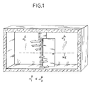
- Fig. 1 shows a building interior with a partition and a large opening, which is designed as a door. If the two building rooms have different temperatures, there is an intensive exchange of air between the two building rooms when the door is opened, with the cooler air flowing to one room in the lower part and the warmer air in the upper part to the other room.
- the point of flow reversal - where the air speed becomes zero - is called the neutral zone NZ.
- the position of the neutral zone depends on the temperatures of the opening geometry and the pressure conditions that are induced by further openings in the building envelope.
- Fig. 2 shows a graphical yet schematic section of a building with two rooms one above the other, which are delimited to the outside by a building wall.
- the actual outer wall of the building is denoted by 1, which is preceded by a building envelope 2, as is customary for facades, so that 2 flow shafts 4 form between the outer wall 1 of the building and the building envelope.
- the flow shafts 4 are continuous from the bottom upwards, while window boxes 9 are inserted in the shafts adjacent to them.
- These window boxes 9 are formed by an outer window 6 and an inner window 5, the inner window 5 - as shown in FIG. 3 - can be opened, while the outer window 6 is fixed in the facade surface.
- the inner window 5 is preferably constructed from insulating glass, so that thermal insulation is created between the window box and the interior of the building.
- the window boxes 9 are delimited by vertical bulkheads 8 and horizontal bulkheads 7, whereby these horizontal bulkheads 7 and vertical bulkheads 8 can also consist of glass.
- overflow openings 10 which can be regulated in terms of their opening size, are provided, through which the space of the window box 9 thus formed is connected to the shafts 4.
- the flow shafts 4 have in the lower area outwardly directed shaft openings 17 which - as shown in FIG. 2 - are closed or - as shown in FIG. 3 for the left shaft - are open.
- ventilation openings 11 are arranged in the window boxes, which - as shown in FIGS. 2 and 3 - can be designed as tilting windows 15 or which - as shown on the far left in FIG. 2 - are designed as ventilation slides 14, through which an air connection between the actual window box 9 and the building interior can be created when the inner window 5 is closed.
- Ventilation openings 12 are provided above the inner windows 5 in the area of the window boxes, which can also be designed as tilting windows 15 (FIG. 3) or as ventilation slides 14.
- 7 ventilation joints 16 are provided in the building envelope 2 in the area of the horizontal bulkheads, which can be opened and closed from the inside of the building. In this way, an air-conducting connection between the window box 9 and the outside can be established.
- the mode of operation of the above-described device according to FIG. 2 is as follows: Due to the solar radiation, the building envelope 2 is heated on the side facing the sun, so that the air heats up in the flow shafts 4 and leads to a buoyancy flow. If - as shown in FIG. 2 - the shaft is closed to the outside in the lower region, the flow shaft 4 sucks the air from the building space through the window box 9 and the overflow opening 10 into the flow shaft 4, depending on the height and temperature, where it flows outside through the upper shaft opening. Air can only be drawn in via the overflow openings 10 if the window box 9 is connected to the interior of the building.
- the position, size and height of the ventilation opening 11, ie the tilting window 15 located below the inner window 5 or the ventilation slide 14, are now dimensioned so that the neutral zone lies above the opening cross-section, this ensures that no warmed-up air comes out when the inner window 5 is closed the area of the window box 9 can get into the building interior, but only air from the building interior can be sucked into the flow duct 4 via the window box 9 and the overflow opening 10.
- a flow of air that is as resistant as possible must be made possible.
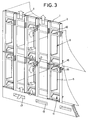
- FIG. 3 shows the use of the incident solar energy with the aid of the arrangement according to FIG. 2.
- the ventilation openings 12 above the inner window 5 are opened, so that now the temperature difference between the inside of the building and the actual window box 9 ensures that heated air flows into the inside of the building in the window box 9.
- the inner window 5 can be opened, so that there can always be a removal of the air warming up at the outer window 6.
- Fig. 3 it is also shown that there is the possibility that the shaft openings 17 can be opened, whereby the buoyancy in the flow shafts 4 can be regulated.
- pitot tubes 18 are placed on the upper shaft openings, which constantly ensure that there is overpressure in the flow shafts.
- the pitot tubes 18, which are rotatably mounted, are always oriented like their weather vane with their opening into the wind and are equipped with weather vane-like guide devices 20.
Abstract
Description
Die Erfindung bezieht sich auf ein Bauwerk mit einer der Gebäudeaußenwand vorgelagerten Gebäudehülle gemäß dem Oberbegriff des Hauptanspruches.The invention relates to a building with a building shell upstream of the building outer wall according to the preamble of the main claim.
Ein gattungsbildendes Bauwerk ist in der EP-481 217-A2 beschrieben.A generic structure is described in EP-481 217-A2.
In der EP-90 794 B1 wird ein Bauwerk beschrieben, wobei die zwischen der Wetterschutzzone und der statischen Schichtzone angeordnete Luftschicht nicht abgeschlossen ausgebildet ist, sondern die Wetterschutzzone wird aus mehreren einzelnen, horizontal gegeneinander versetzt angeordneten Außenverkleidungsplatten gebildet, so daß sich in dieser Luftschicht keine wesentliche Thermik bei Wärmeeinstrahlung ausbilden kann. Im Bereich der Fenster ist diese Luftschicht sowieso dann unterbrochen, wenn die Beschattungsvorrichtung herabgelassen ist. Die Wetterschutzzone ist im Bereich der Fenster unterbrochen, und das im Bereich der statischen Schichtzone bzw. der Wärmedämmzone angeordnete Fenster steht also mit seiner Außenseite unmittelbar mit der Umgebungsluft des Bauwerkes in Verbindung. Diese bekannten Anordnungen weisen daher üblicherweise kein zu öffnendes Fenster auf, sondern die Klimatisierung des Gebäudeinnenraumes erfolgt durch eine Klimaanlage.A structure is described in EP-90 794 B1, the air layer arranged between the weather protection zone and the static layer zone not being finished, but the weather protection zone being formed from a plurality of individual outer cladding panels arranged horizontally offset from one another, so that none are formed in this air layer can form essential thermals when exposed to heat. In the area of the windows, this air layer is interrupted anyway when the shading device is lowered. The weather protection zone is in the area the window is interrupted, and the outside of the window located in the area of the static layer zone or the thermal insulation zone is thus directly connected to the ambient air of the building. These known arrangements therefore usually do not have a window that can be opened, but the air conditioning of the interior of the building takes place by means of an air conditioning system.
In der DE-25 19 658 A1 wird eine zweischalige Fassadenkonstruktion beschrieben, bei welcher die innere Schale als fest geschlossener, luftdichter Fassadenteil ausgebildet ist. Vor dieser inneren Schale ist eine Außenfassade angeordnet, bei der der so gebildete Zwischenraum an eine Luftzufuhr und einen Luftauslaß angeschlossen ist. Die in diesem Zwischenraum gefüllte Luft kann klimatisiert werden.DE-25 19 658 A1 describes a double-shell facade construction in which the inner shell is designed as a tightly closed, airtight facade part. An outer facade is arranged in front of this inner shell, in which the intermediate space thus formed is connected to an air supply and an air outlet. The air filled in this space can be air-conditioned.
Aus der DE-24 07 865 A1 ist ein Fassadenelement bekanntgeworden, durch dessen Einsatz ebenfalls eine Klimahülle geschaffen werden soll. In dieser Fassade ist auch ein Fenster vorgesehen, dessen Fensterzwischenraum mit dieser Klimahülle in Verbindung steht. Die Gesamtheit aus Außen- und Innenfenster kann geöffnet werden, wobei dann aber eine Unterbrechung zur luftführenden Schicht erfolgt, eine Belüftung des Gebäudeinneren aus dem zwischen Außen- und Innenfassade gebildeten Zwischenraum ist nicht möglich.A facade element has become known from DE-24 07 865 A1, the use of which is also intended to create a climate envelope. A window is also provided in this facade, the space between the windows being connected to this climate envelope. The whole of the exterior and interior windows can be opened, but then there is an interruption to the air-guiding layer, ventilation of the interior of the building from the space formed between the exterior and interior facade is not possible.
Aus der DE-PS 22 31 972 ist es bekannt, vor der Außenwand eines Gebäudes mit geringem Abstand ein einen großen Strahlungskoeffizienten aufweisendes Fassadenelement vorzusehen, wobei der Zwischenraum zwischen der Außenwand und dem Fassadenelement ständig mit dem Unterteil des Aufenthaltsraumes verbunden ist. Der Zwischenraum zwischen Außenwand und Fassadenelement ist aber nicht im unteren Bereich mit der Außenluft verbunden, so daß hier im Prinzip nur ein geschlossener Kreislauf geschaffen wird.From DE-PS 22 31 972 it is known to provide a large radiation coefficient facade element in front of the outer wall of a building at a short distance, the gap between the outer wall and the facade element constantly is connected to the lower part of the lounge. However, the space between the outer wall and the facade element is not connected to the outside air in the lower area, so that in principle only a closed circuit is created here.
In der EP-467 876 A2 wird ein Hochhaus mit einem zwischen Kernwand und Gebäudehülle befindlichen Hinterlüftungs-Zwischenraum vorgeschlagen. Der in dem Hinterlüftungs-Zwischenraum herrschende natürliche Auftrieb, die sogenannte "Thermo-Syphon-Wirkung", wird dazu ausgenutzt, um aus dem Gebäude verbrauchte Luft abzusaugen.EP-467 876 A2 proposes a high-rise building with a ventilation space between the core wall and the building envelope. The natural buoyancy prevailing in the rear ventilation space, the so-called "thermo-siphon effect", is used to extract used air from the building.
Aus der EP-481 217 A2 ist eine ähnliche Einrichtung bekannt.A similar device is known from EP-481 217 A2.
Auf der der Sonne zugewandten Fassadenseite sind üblicherweise in dem Fassadenzwischenraum Sonnenschutzvorrichtungen angeordnet, die bei solarer Einstrahlung eine große Aufheizung der Luft im Bereich der Strömungsschächte und der Fensterkästen bewirken. Wird nun zu Lüftungszwecken auf dieser Gebäudeseite eine große Öffnung, z. B. ein Fensterflügel, im Bereich der Gebäudeaußenwand geöffnet, kommt es zu einem intensiven Luftaustausch zwischen diesem Raum und dem Fensterkasten, so daß nahezu die gesamte, im Fensterkasten absorbierte Wärme in den Raum gelüftet wird und entweder zu unbehaglichen Raumlufttemperaturen führt oder eine evtl. vorhandene Klimaanlage stark belastet.On the facade side facing the sun, sun protection devices are usually arranged in the space between the facades, which cause a large heating of the air in the region of the flow shafts and the window boxes in the case of solar radiation. If there is a large opening on this side of the building for ventilation purposes, e.g. B. a window sash, opened in the area of the building's outer wall, there is an intensive air exchange between this room and the window box, so that almost all of the heat absorbed in the window box is vented into the room and either leads to uncomfortable room air temperatures or a possibly existing Air conditioning system heavily loaded.
Der Erfindung liegt demgegenüber die Aufgabe zugrunde, eine gute Innenbelüftung des Gebäuderaumes zu erreichen.In contrast, the invention is based on the object of providing good internal ventilation of the building space to reach.
Diese der Erfindung zugrundeliegende Aufgabe wird durch die Lehre des Hauptanspruches gelöst.This object on which the invention is based is achieved by the teaching of the main claim.
Vorteilhafte Ausgestaltungen sind in den Unteransprüchen erläutert.Advantageous configurations are explained in the subclaims.
Mit anderen Worten ausgedrückt wird gemäß der Erfindung vorgeschlagen, daß durch zweckmäßige Steuerung der luftführenden Öffnungen und unter gezielter Ausnutzung der natürlichen Auftriebskräfte über eine sich einstellende Querlüftung der Luftaustausch im Sommer erhöht wird, der Eintritt von relativ kühler Außenluft auf der sonnenabgewandten Seite in das Gebäude ermöglicht wird, daß aber andererseits auf der sonnenzugewandten Gebäudeseite kein Eintritt der erwärmten Luft aus dem Raum zwischen der Gebäudeaußenwand und der Gebäudehülle, also aus dem Fassadenzwischenraum in den Gebäuderaum erfolgt.In other words, it is proposed according to the invention that by appropriately controlling the air-guiding openings and using the natural buoyancy forces in a targeted manner, air exchange in summer is increased by means of transverse ventilation, which allows relatively cool outside air to enter the building on the side facing away from the sun is that, on the other hand, on the side of the building facing the sun, the heated air does not enter from the space between the outer wall of the building and the building envelope, that is to say from the space between the facades into the building space.
Bei großen Öffnungen, wie sie u. a. Fenster darstellen, kommt es zu bidirektionalen Strömungen sobald kleinere Temperaturdifferenzen zwischen beiden Seiten der Öffnung bestehen und die neutrale Zone sich im Bereich der Öffnungsfläche befindet. Die Lage dieser neutralen Zone ist aber beeinflußbar, wenn man sich gemäß der Erfindung den thermischen Auftrieb in den Strömungsschächten zunutzemacht.With large openings, as u. a. Representing windows, bidirectional flows occur as soon as there are small temperature differences between both sides of the opening and the neutral zone is in the area of the opening area. The position of this neutral zone can be influenced, however, if one takes advantage of the thermal buoyancy in the flow shafts according to the invention.
Wegen der auf der sonnenzugewandten Fassadenseite hohen Schachttemperaturen entsteht dort ein heftiger Auftrieb. Wird der Schacht im unteren Bereich nach außen hin geschlossen, so saugt der Schacht je nach Höhe und Temperatur die Luft verstärkt aus dem Raum durch den Fensterkasten und die Überströmöffnung in den Schacht, wo sie über die obere Schachtöffnung ins Freie strömt. Wird nunmehr die Lage, Größe und Höhe der Öffnung an der Gebäudeaußenwand - d. h. also die Öffnung, die vom Fensterkasten in den Gebäudeinnenraum führt - so bemessen, daß die neutrale Zone oberhalb des Öffnungsquerschnittes liegt, ist damit sichergestellt, daß keine aufgewärmte Fensterkastenluft in den Gebäudeinnenraum gelangt, sondern nur Luft aus dem Gebäudeinnenraum über den Fensterkasten in den Strömungsschacht strömt. Auf den sonnenabgewandten Gebäudeseiten muß eine möglichst widerstandsfreie Nachströmung von Luft ermöglicht werden.Because of the high shaft temperatures on the sun-facing facade side, there is a violent buoyancy. If the shaft in the lower area is closed to the outside, the shaft sucks the air out of the room depending on the height and temperature through the window box and the overflow opening into the shaft, where it flows outside via the upper shaft opening. If the position, size and height of the opening on the outer wall of the building - i.e. the opening that leads from the window box into the interior of the building - is dimensioned so that the neutral zone is above the opening cross-section, this ensures that no heated window box air enters the interior of the building reaches, but only air from the building interior flows over the window box into the flow shaft. On the sides of the building facing away from the sun, a flow of air that is as resistant as possible must be made possible.
Aufgrund dieser Querlüftung kommt es auf der sonnenzugewandten Fassadenseite zu einer Abfuhr der im Fassadenzwischenraum absorbierten Solarenergie nach außen und somit wegen der reduzierten Wärmetransmission ins Gebäude zu einer Verringerung der Kühllast.Due to this cross-ventilation, the solar energy absorbed in the space between the facades is dissipated to the outside on the side of the facade facing the sun and thus the cooling load is reduced due to the reduced heat transmission into the building.
Damit der Winddruck auf der sonnenzugewandten Seite der Querlüftung nicht entgegenwirkt, werden dort alle Außenfugen der Fensterkästen geschlossen. Weiterhin werden die Schachtenden auf der sonnenzugewandten Seite z. B. über einen düsenartigen Aufsatz so ausgebildet, daß der Wind unabhängig von der Richtung immer einen Unterdruck erzeugt und damit die Querlüftung unterstützt.So that the wind pressure on the sun-facing side of the cross ventilation does not counteract, all outer joints of the window boxes are closed there. Furthermore, the shaft ends on the sun-facing side z. B. formed over a nozzle-like attachment so that the wind always creates a vacuum regardless of the direction and thus supports the cross ventilation.
Auf den sonnenabgewandten Seiten können die Schachtenden so ausgeführt werden, daß dort der Wind unabhängig von der Richtung immer einen Überdruck erzeugt, was z. B. über ein passiv oder aktiv in den Wind positioniertes Staurohr oder ähnliches erfolgen kann.On the sides facing away from the sun, the shaft ends can be designed so that there the wind always creates an overpressure regardless of the direction. B. via a passive or active in the Pitot tube positioned in the wind or the like can be done.
Die Nutzung der eingestrahlten Solarenergie kann während kühlerer Wettersituationen unter Berücksichtigung der thermischen Behaglichkeit der Bewohner über eine weitere Öffnung im oberen Fensterkastenbereich erzielt werden. Die Temperaturdifferenz zwischen dem Gebäudeinneren und dem eigentlichen Fensterkasten sorgt dann für einen einstellbaren Luftaustausch, wobei nicht kalte Außenluft, sondern im Fensterkasten aufgewärmte Luft in den Raum strömt.The use of the irradiated solar energy can be achieved during cooler weather situations, taking into account the thermal comfort of the residents, via a further opening in the upper window box area. The temperature difference between the inside of the building and the actual window box then ensures an adjustable air exchange, whereby not cold outside air, but air warmed up in the window box flows into the room.
Hierbei ist es sehr sinnvoll, die eigentliche, dem Gebäudeinnenraum zugewandte Fensterscheibe als Isolierglasscheibe auszubilden, so daß dadurch eine thermische Abschottung gegenüber dem ggf. heißeren Fensterkasteninnenraum erfolgt.It is very useful here to design the actual window pane facing the building interior as an insulating glass pane, so that this results in thermal isolation from the possibly hotter window box interior.
Die Nutzung der solaren Strahlungsenergie kann während kühlerer Wettersituation noch dadurch verbessert werden, daß der Sonnenschutz auf einer Seite stark strahlungsabsorbierend ausgeführt wird, z. B. über die Art der Beschichtung und auf der anderen Seite stark reflektierend. Bei kühlem Wetter ist die strahlungsabsorbierende Seite der Sonne zugewandt, bei warmem Wetter die reflektierende Seite. Diese Art des Sonnenschutzes wäre z. B. mit üblichen Lamellenkonstruktionen mit entsprechender Mechanik leicht realisierbar.The use of solar radiation energy can be improved during cooler weather by the fact that the sun protection on one side is highly radiation-absorbing, z. B. on the type of coating and on the other hand highly reflective. In cool weather the radiation absorbing side faces the sun, in warm weather the reflective side. This type of sun protection would be e.g. B. easily implemented with conventional lamella constructions with appropriate mechanics.
Ausführungsbeispiele der Erfindung werden nachfolgend anhand der Zeichnungen erläutert. Die Zeichnungen zeigen dabei in
- Fig. 1
- zur Verdeutlichung der neutralen Zone eine geöffnete Tür innerhalb eines Gebäuderaumes, in
- Fig. 2
- in einer schaubildlichen Darstellungsweise die sonnenzugewandte Gebäudeseite, die gemäß der Erfindung ausgebildet ist, in
- Fig. 3
- eine Darstellung gemäß Fig. 2 der sonnenzugewandten Gebäudeseite im Winter, um die Solarwärme in den Gebäudeinnenraum zu holen, in
- Fig. 4
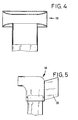
- schematisch einen düsenartigen Schachtaufsatz, der auf die obere Schachtöffnung aufgesetzt ist und in
- Fig. 5
- schematisch ein drehbares Staurohr, das auf die obere Schachtöffnung aufgesetzt ist.
- Fig. 1
- to illustrate the neutral zone, an open door within a building room, in
- Fig. 2
- in a diagrammatic representation the side of the building facing the sun, which is designed according to the invention, in
- Fig. 3
- 2 shows the side of the building facing the sun in winter in order to bring the solar heat into the interior of the building
- Fig. 4
- schematically a nozzle-like shaft attachment, which is placed on the upper shaft opening and in
- Fig. 5
- schematically a rotatable pitot tube, which is placed on the upper shaft opening.
Die Fig. 1 zeigt einen Gebäudeinnenraum mit einer Trennwand und einer großen Öffnung, die als Tür ausgebildet ist. Liegen in den beiden Gebäuderäumen unterschiedliche Temperaturen vor, kommt es bei Öffnung der Tür zu einem intensiven Luftaustausch zwischen den beiden Gebäuderäumen, wobei die kühlere Luft im unteren Teil zum einen Raum strömt und die wärmere Luft im oberen Teil der Öffnung zum anderen Raum. Die Stelle der Strömungsumkehr - dort wo die Luftgeschwindigkeit zu Null wird - nennt man neutrale Zone NZ. Die Lage der neutralen Zone hängt von den Temperaturen der Öffnungsgeometrie und den Druckverhältnissen ab, die durch weitere Öffnungen in der Gebäudehülle induziert werden.Fig. 1 shows a building interior with a partition and a large opening, which is designed as a door. If the two building rooms have different temperatures, there is an intensive exchange of air between the two building rooms when the door is opened, with the cooler air flowing to one room in the lower part and the warmer air in the upper part to the other room. The point of flow reversal - where the air speed becomes zero - is called the neutral zone NZ. The position of the neutral zone depends on the temperatures of the opening geometry and the pressure conditions that are induced by further openings in the building envelope.
Bei großen Öffnungen, wie sie z. B. Fenster darstellen, kommt es zu den in Fig. 1 dargestellten bidirektionalen Strömungen, sobald kleinere Temperaturdifferenzen ϑ₁ < ϑ₂ zwischen den beiden Seiten der Öffnungen bestehen und die neutrale Zone NZ sich im Bereich der Öffnungsfläche befindet. Diese neutrale Zone NZ ist beeinflußbar.With large openings, such as. B. represent windows, it comes to the bidirectional shown in Fig. 1 Currents as soon as there are smaller temperature differences ϑ₁ <ϑ₂ between the two sides of the openings and the neutral zone NZ is in the area of the opening area. This neutral zone NZ can be influenced.
Fig. 2 zeigt schaubildlich und doch schematisch einen Ausschnitt aus einem Gebäude mit zwei übereinanderliegenden Räumen, die nach außen hin durch eine Gebäudewand begrenzt werden. Hierbei ist mit 1 die eigentliche Gebäudeaußenwand bezeichnet, der eine Gebäudehülle 2 vorgesetzt ist, wie das bei Fassaden üblich ist, so daß sich zwischen der Gebäudeaußenwand 1 und der Gebäudehülle 2 Strömungsschächte 4 bilden. Die Strömungsschächte 4 sind von unten nach oben hin durchgehend, während in den danebenliegenden Schächten Fensterkästen 9 eingesetzt sind. Diese Fensterkästen 9 werden von einem Außenfenster 6 und einem Innenfenster 5 gebildet, wobei das Innenfenster 5 - wie dies Fig. 3 zeigt - geöffnet werden kann, während das Außenfenster 6 feststehend in der Fassadenfläche ausgebildet ist. Vorzugsweise ist das Innenfenster 5 aus Isolierglas aufgebaut, so daß eine Wärmeisolation zwischen dem Fensterkasten und dem Gebäudeinnenraum geschaffen wird.Fig. 2 shows a graphical yet schematic section of a building with two rooms one above the other, which are delimited to the outside by a building wall. Here, the actual outer wall of the building is denoted by 1, which is preceded by a
Die Fensterkästen 9 werden durch vertikale Schotten 8 und horizontale Schotten 7 abgegrenzt, wobei diese horizontalen Schotten 7 und vertikalen Schotten 8 auch aus Glas bestehen können. In den vertikalen Schotten 8 sind ggf. in ihrer Öffnungsgröße regelbare Überströmöffnungen 10 vorgesehen, durch die der Raum des so gebildeten Fensterkastens 9 mit den Schächten 4 in Verbindung steht.The
Die Strömungsschächte 4 weisen im unteren Bereich nach außen hingerichtete Schachtöffnungen 17 auf, die - wie dies in Fig. 2 dargestellt ist - geschlossen sind oder - wie in Fig. 3 beim linken Schacht dargestellt - geöffnet sind.The flow shafts 4 have in the lower area outwardly directed
Unterhalb der Innenfenster 5 sind in den Fensterkästen Lüftungsöffnungen 11 angeordnet, die - wie dies Fig. 2 und Fig. 3 zeigen - als Kippfenster 15 ausgebildet sein können oder die auch - wie dies Fig. 2 ganz links zeigt - als Lüftungsschieber 14 gestaltet sind, durch die aber bei geschlossenem Innenfenster 5 eine Luftverbindung zwischen dem eigentlichen Fensterkasten 9 und dem Gebäudeinnenraum geschaffen werden kann.Below the
Oberhalb der Innenfenster 5 sind im Bereich der Fensterkästen Lüftungsöffnungen 12 vorgesehen, die ebenfalls als Kippfenster 15 ausgebildet sein können (Fig. 3) oder als Lüftungsschieber 14 ausgebildet sind.
Außerdem sind in der Gebäudehülle 2 im Bereich der horizontalen Schotten 7 Lüftungsfugen 16 vorgesehen, die vom Inneren des Gebäudes her geöffnet und geschlossen werden können. Hierdurch kann eine luftführende Verbindung zwischen Fensterkasten 9 und außen hergestellt werden.In addition, 7
Die Wirkungsweise dieser vorbeschriebenen Einrichtung gemäß Fig. 2 ist wie folgt:
Aufgrund der Sonneneinstrahlung wird die Gebäudehülle 2 auf der sonnenzugewandten Seite erhitzt, so daß die Luft sich in den Strömungsschächten 4 erwärmt und zu einer Auftriebsströmung führt. Wird - wie dies in Fig. 2 dargestellt ist - der Schacht im unteren Bereich nach außen hin geschlossen, so saugt der Strömungsschacht 4 je nach Höhe und Temperatur die Luft verstärkt aus dem Gebäuderaum durch den Fensterkasten 9 und die Überströmöffnung 10 in den Strömungsschacht 4, wo sie über die obere Schachtöffnung ins Freie strömt. Ein Ansaugen von Luft über die Überströmöffnungen 10 ist aber nur möglich, wenn der Fensterkasten 9 eine Verbindung mit dem Gebäudeinnenraum hat. Wird nunmehr bei geschlossenem Innenfenster 5 die Lage, Größe und Höhe der Lüftungsöffnung 11, d. h. des unterhalb des Innenfensters 5 befindlichen Kippfensters 15 oder des Lüftungsschiebers 14 so bemessen, daß die neutrale Zone oberhalb des Öffnungsquerschnittes liegt, ist damit sichergestellt, daß keine aufgewärmte Luft aus dem Bereich des Fensterkastens 9 in den Gebäudeinnenraum gelangenkann, sondern nur Luft aus dem Gebäudeinnenraum über den Fensterkasten 9 und die Überströmöffnung 10 in den Strömungsschacht 4 gesaugt werden kann. Auf der sonnenabgewandten Gebäudeseite muß eine möglichst widerstandsfreie Nachströmung der Luft ermöglicht werden.The mode of operation of the above-described device according to FIG. 2 is as follows:
Due to the solar radiation, the
In Fig. 3 ist anhand der Anordnung gemäß Fig. 2 die Nutzung der eingestrahlten Solarenergie dargestellt. In diesem Fall werden die Lüftungsöffnungen 12 oberhalb der Innenfenster 5 geöffnet, so daß nunmehr die Temperaturdifferenz zwischen dem Gebäudeinneren und dem eigentlichen Fensterkasten 9 dafür sorgt, daß im Fensterkasten 9 aufgewärmte Luft in den Gebäudeinnenraum strömt. In Fig. 3 ist auch dargestellt, daß die Innenfenster 5 geöffnet werden können, so daß hier stets ein Abtransport der sich am Außenfenster 6 erwärmenden Luft erfolgen kann.FIG. 3 shows the use of the incident solar energy with the aid of the arrangement according to FIG. 2. In this case, the
In Fig. 3 ist auch dargestellt, daß die Möglichkeit besteht, daß die Schachtöffnungen 17 geöffnet werden können, wodurch der Auftrieb in den Strömungsschächten 4 reguliert werden kann.In Fig. 3 it is also shown that there is the possibility that the
Damit der Winddruck auf der sonnenzugewandten Seite den Auftrieb in den Strömungsschächten 4 nicht behindert, werden dort die in Fig. 2 erkennbaren Lüftungsfugen 16 geschlossen die oberen Schachtenden der Strömungsschächte 4 können mit düsenartigen Aufsätzen versehen werden, die dafür sorgen, daß auch im Bereich der oberen Schachtöffnung ein Unterdruck erzeugt wird. Ein solcher düsenartiger Schachtaufsatz 19 ist in Fig. 4 dargestellt.So that the wind pressure on the sun-facing side does not impede the buoyancy in the flow shafts 4, the
Will man umgekehrt kühlere Luft durch die Strömungsschächte 4 zu den Fensterkästen führen, kann es vorteilhaft sein, auf die oberen Schachtöffnungen Staurohre 18 aufzusetzen, die ständig dafür sorgen, daß in den Strömungsschächten ein Überdruck herrscht. Die Staurohre 18, die drehbar gelagert sind, richten sich dabei ähnlich einer Wetterfahne stets mit ihrer Öffnung in den Wind und sind mit wetterfahnenähnlichen Leitvorrichtungen 20 ausgerüstet.Conversely, if you want to lead cooler air through the flow shafts 4 to the window boxes, it can be advantageous to place
Claims (13)
Applications Claiming Priority (2)
| Application Number | Priority Date | Filing Date | Title |
|---|---|---|---|
| DE4238135 | 1992-11-12 | ||
| DE4238135A DE4238135A1 (en) | 1992-11-12 | 1992-11-12 | Cross ventilation with Twinface |
Publications (2)
| Publication Number | Publication Date |
|---|---|
| EP0601335A1 true EP0601335A1 (en) | 1994-06-15 |
| EP0601335B1 EP0601335B1 (en) | 1996-03-20 |
Family
ID=6472669
Family Applications (1)
| Application Number | Title | Priority Date | Filing Date |
|---|---|---|---|
| EP93117938A Expired - Lifetime EP0601335B1 (en) | 1992-11-12 | 1993-11-05 | Ventilation for a building with a curtain wall |
Country Status (3)
| Country | Link |
|---|---|
| EP (1) | EP0601335B1 (en) |
| AT (1) | ATE135779T1 (en) |
| DE (2) | DE4238135A1 (en) |
Cited By (6)
| Publication number | Priority date | Publication date | Assignee | Title |
|---|---|---|---|---|
| AT410456B (en) * | 2000-12-12 | 2003-05-26 | Consultplan Tech Buero Ges M B | Multi-storey high building wit metal profiles |
| WO2003058131A1 (en) * | 2002-01-07 | 2003-07-17 | Karl-Heinz Petzinka | Building and method for air conditioning the interior of a building |
| US20100279597A1 (en) * | 2007-12-11 | 2010-11-04 | Byung Nam Cho | Building circulation system using curtain wall as ventilator |
| CN103255930A (en) * | 2012-02-15 | 2013-08-21 | 天津三春科技有限公司 | Novel low-carbon livable building technique integrating house, wind and light and capable of outputting electric power |
| DE102013018627A1 (en) | 2013-11-06 | 2015-05-07 | Doris Frenzel | Atmunasactive base shell for the housing stock |
| EP3109565A1 (en) | 2015-06-26 | 2016-12-28 | Doris Frenzel | Breathable basis sheath |
Citations (3)
| Publication number | Priority date | Publication date | Assignee | Title |
|---|---|---|---|---|
| DE3928259A1 (en) * | 1989-08-26 | 1991-02-28 | Scheu & Wirth Ag | Window component - has integral ducting and filtration built into frame posts, and contains roller sunblind assembly |
| EP0467876A2 (en) * | 1990-07-14 | 1992-01-22 | Rls-Bautechnologie Ag | High-rise building |
| EP0481217A2 (en) * | 1990-10-13 | 1992-04-22 | ALCO-Systeme GmbH | Building |
Family Cites Families (4)
| Publication number | Priority date | Publication date | Assignee | Title |
|---|---|---|---|---|
| DE106292C (en) * | ||||
| FR2144066A5 (en) * | 1971-06-29 | 1973-02-09 | Trombe Felix | |
| DE3418417A1 (en) * | 1984-05-17 | 1984-12-13 | Richard 8047 Karlsfeld Trappe | Automatic fresh-air ventilation and aeration |
| DE3508876A1 (en) * | 1985-03-13 | 1986-09-18 | "Schako" Metallwarenfabrik Ferdinand Schad KG Zweigniederlassung Kolbingen, 7201 Kolbingen | Method and device for air-conditioning spaces |
-
1992
- 1992-11-12 DE DE4238135A patent/DE4238135A1/en not_active Ceased
-
1993
- 1993-11-05 DE DE59301956T patent/DE59301956D1/en not_active Expired - Fee Related
- 1993-11-05 AT AT93117938T patent/ATE135779T1/en not_active IP Right Cessation
- 1993-11-05 EP EP93117938A patent/EP0601335B1/en not_active Expired - Lifetime
Patent Citations (3)
| Publication number | Priority date | Publication date | Assignee | Title |
|---|---|---|---|---|
| DE3928259A1 (en) * | 1989-08-26 | 1991-02-28 | Scheu & Wirth Ag | Window component - has integral ducting and filtration built into frame posts, and contains roller sunblind assembly |
| EP0467876A2 (en) * | 1990-07-14 | 1992-01-22 | Rls-Bautechnologie Ag | High-rise building |
| EP0481217A2 (en) * | 1990-10-13 | 1992-04-22 | ALCO-Systeme GmbH | Building |
Cited By (7)
| Publication number | Priority date | Publication date | Assignee | Title |
|---|---|---|---|---|
| AT410456B (en) * | 2000-12-12 | 2003-05-26 | Consultplan Tech Buero Ges M B | Multi-storey high building wit metal profiles |
| WO2003058131A1 (en) * | 2002-01-07 | 2003-07-17 | Karl-Heinz Petzinka | Building and method for air conditioning the interior of a building |
| US20100279597A1 (en) * | 2007-12-11 | 2010-11-04 | Byung Nam Cho | Building circulation system using curtain wall as ventilator |
| CN103255930A (en) * | 2012-02-15 | 2013-08-21 | 天津三春科技有限公司 | Novel low-carbon livable building technique integrating house, wind and light and capable of outputting electric power |
| CN103255930B (en) * | 2012-02-15 | 2015-09-23 | 天津三春科技有限公司 | The livable building new technology of low-carbon (LC) of a kind of room, wind, light Trinity energy output power |
| DE102013018627A1 (en) | 2013-11-06 | 2015-05-07 | Doris Frenzel | Atmunasactive base shell for the housing stock |
| EP3109565A1 (en) | 2015-06-26 | 2016-12-28 | Doris Frenzel | Breathable basis sheath |
Also Published As
| Publication number | Publication date |
|---|---|
| ATE135779T1 (en) | 1996-04-15 |
| EP0601335B1 (en) | 1996-03-20 |
| DE59301956D1 (en) | 1996-04-25 |
| DE4238135A1 (en) | 1994-05-19 |
Similar Documents
| Publication | Publication Date | Title |
|---|---|---|
| EP0467876B1 (en) | High-rise building | |
| DE202006020354U1 (en) | Temperature, heat and / or cold barrier in particular for or in a device for air conditioning of buildings | |
| EP0093364B1 (en) | Sound absorbing and heat insulating compound window with a ventilating device | |
| EP0601335B1 (en) | Ventilation for a building with a curtain wall | |
| DE3732545A1 (en) | Ventilation system for extracting waste air from rooms | |
| EP0692686B1 (en) | Double wall façade | |
| CH633071A5 (en) | Positively ventilated façade element | |
| EP0951630B1 (en) | Method for ventilating a room and device for carrying out the method | |
| DE3928259A1 (en) | Window component - has integral ducting and filtration built into frame posts, and contains roller sunblind assembly | |
| DE1804281C3 (en) | Arrangement for heating or cooling for installation in window frames or the like | |
| DE3002513C2 (en) | Roof and the loft space limited by it for a solar-heated house | |
| DE10033535A1 (en) | double facade | |
| DE3026635A1 (en) | Ventilated double skinned facade window section - has movable heat screen -pened or closed between skins to duct air | |
| DE4431928A1 (en) | Window with heat and sound insulative properties for dwelling | |
| DE3728698A1 (en) | Air conditioning plant | |
| DE202007011819U1 (en) | Ventilation on double façade | |
| EP0090794B1 (en) | Building construction | |
| EP0003725B1 (en) | Longitudinally ventilated double-glazed window with interior curtain | |
| EP0481217B1 (en) | Building | |
| DE2808432A1 (en) | Ventilated double skinned facade with heat conservation - has heat emitter between shells in condensation subjected area | |
| DE19818380B4 (en) | double window | |
| AT410456B (en) | Multi-storey high building wit metal profiles | |
| DE3938906A1 (en) | Sunlight protection for room - involves two roller blinds suspended in exhaust air channel | |
| DE3333196A1 (en) | Space limiting element | |
| EP0005259B1 (en) | Air conditioning system for a closed space |
Legal Events
| Date | Code | Title | Description |
|---|---|---|---|
| PUAI | Public reference made under article 153(3) epc to a published international application that has entered the european phase |
Free format text: ORIGINAL CODE: 0009012 |
|
| 17P | Request for examination filed |
Effective date: 19940407 |
|
| AK | Designated contracting states |
Kind code of ref document: A1 Designated state(s): AT CH DE DK FR GB LI NL SE |
|
| 17Q | First examination report despatched |
Effective date: 19950505 |
|
| GRAA | (expected) grant |
Free format text: ORIGINAL CODE: 0009210 |
|
| AK | Designated contracting states |
Kind code of ref document: B1 Designated state(s): AT CH DE DK FR GB LI NL SE |
|
| PG25 | Lapsed in a contracting state [announced via postgrant information from national office to epo] |
Ref country code: NL Free format text: LAPSE BECAUSE OF FAILURE TO SUBMIT A TRANSLATION OF THE DESCRIPTION OR TO PAY THE FEE WITHIN THE PRESCRIBED TIME-LIMIT Effective date: 19960320 Ref country code: GB Effective date: 19960320 Ref country code: DK Effective date: 19960320 |
|
| REF | Corresponds to: |
Ref document number: 135779 Country of ref document: AT Date of ref document: 19960415 Kind code of ref document: T |
|
| REF | Corresponds to: |
Ref document number: 59301956 Country of ref document: DE Date of ref document: 19960425 |
|
| REG | Reference to a national code |
Ref country code: CH Ref legal event code: NV Representative=s name: PATENTANWALTSBUERO EDER AG |
|
| ET | Fr: translation filed | ||
| PG25 | Lapsed in a contracting state [announced via postgrant information from national office to epo] |
Ref country code: SE Effective date: 19960620 |
|
| NLV1 | Nl: lapsed or annulled due to failure to fulfill the requirements of art. 29p and 29m of the patents act | ||
| GBV | Gb: ep patent (uk) treated as always having been void in accordance with gb section 77(7)/1977 [no translation filed] |
Effective date: 19960320 |
|
| PLBQ | Unpublished change to opponent data |
Free format text: ORIGINAL CODE: EPIDOS OPPO |
|
| PLBI | Opposition filed |
Free format text: ORIGINAL CODE: 0009260 |
|
| PLBF | Reply of patent proprietor to notice(s) of opposition |
Free format text: ORIGINAL CODE: EPIDOS OBSO |
|
| PLBF | Reply of patent proprietor to notice(s) of opposition |
Free format text: ORIGINAL CODE: EPIDOS OBSO |
|
| 26 | Opposition filed |
Opponent name: JORDAN, PAUL, DIPL.-ING. Effective date: 19961219 |
|
| PLBF | Reply of patent proprietor to notice(s) of opposition |
Free format text: ORIGINAL CODE: EPIDOS OBSO |
|
| PLBO | Opposition rejected |
Free format text: ORIGINAL CODE: EPIDOS REJO |
|
| PLBN | Opposition rejected |
Free format text: ORIGINAL CODE: 0009273 |
|
| STAA | Information on the status of an ep patent application or granted ep patent |
Free format text: STATUS: OPPOSITION REJECTED |
|
| 27O | Opposition rejected |
Effective date: 19990212 |
|
| PGFP | Annual fee paid to national office [announced via postgrant information from national office to epo] |
Ref country code: FR Payment date: 20041118 Year of fee payment: 12 |
|
| PGFP | Annual fee paid to national office [announced via postgrant information from national office to epo] |
Ref country code: AT Payment date: 20041122 Year of fee payment: 12 |
|
| PGFP | Annual fee paid to national office [announced via postgrant information from national office to epo] |
Ref country code: CH Payment date: 20041123 Year of fee payment: 12 |
|
| PGFP | Annual fee paid to national office [announced via postgrant information from national office to epo] |
Ref country code: DE Payment date: 20051104 Year of fee payment: 13 |
|
| PG25 | Lapsed in a contracting state [announced via postgrant information from national office to epo] |
Ref country code: AT Free format text: LAPSE BECAUSE OF NON-PAYMENT OF DUE FEES Effective date: 20051105 |
|
| PG25 | Lapsed in a contracting state [announced via postgrant information from national office to epo] |
Ref country code: LI Free format text: LAPSE BECAUSE OF NON-PAYMENT OF DUE FEES Effective date: 20051130 Ref country code: CH Free format text: LAPSE BECAUSE OF NON-PAYMENT OF DUE FEES Effective date: 20051130 |
|
| REG | Reference to a national code |
Ref country code: CH Ref legal event code: PL |
|
| PG25 | Lapsed in a contracting state [announced via postgrant information from national office to epo] |
Ref country code: FR Free format text: LAPSE BECAUSE OF NON-PAYMENT OF DUE FEES Effective date: 20060731 |
|
| REG | Reference to a national code |
Ref country code: FR Ref legal event code: ST Effective date: 20060731 |
|
| PG25 | Lapsed in a contracting state [announced via postgrant information from national office to epo] |
Ref country code: DE Free format text: LAPSE BECAUSE OF NON-PAYMENT OF DUE FEES Effective date: 20070601 |