EP0598461B1 - Flexible cannula - Google Patents
Flexible cannula Download PDFInfo
- Publication number
- EP0598461B1 EP0598461B1 EP93250272A EP93250272A EP0598461B1 EP 0598461 B1 EP0598461 B1 EP 0598461B1 EP 93250272 A EP93250272 A EP 93250272A EP 93250272 A EP93250272 A EP 93250272A EP 0598461 B1 EP0598461 B1 EP 0598461B1
- Authority
- EP
- European Patent Office
- Prior art keywords
- tube
- flexible
- top piece
- proximal end
- cannula
- Prior art date
- Legal status (The legal status is an assumption and is not a legal conclusion. Google has not performed a legal analysis and makes no representation as to the accuracy of the status listed.)
- Expired - Lifetime
Links
Images
Classifications
-
- A—HUMAN NECESSITIES
- A61—MEDICAL OR VETERINARY SCIENCE; HYGIENE
- A61B—DIAGNOSIS; SURGERY; IDENTIFICATION
- A61B17/00—Surgical instruments, devices or methods
- A61B17/34—Trocars; Puncturing needles
- A61B17/3417—Details of tips or shafts, e.g. grooves, expandable, bendable; Multiple coaxial sliding cannulas, e.g. for dilating
- A61B17/3421—Cannulas
-
- A—HUMAN NECESSITIES
- A61—MEDICAL OR VETERINARY SCIENCE; HYGIENE
- A61L—METHODS OR APPARATUS FOR STERILISING MATERIALS OR OBJECTS IN GENERAL; DISINFECTION, STERILISATION OR DEODORISATION OF AIR; CHEMICAL ASPECTS OF BANDAGES, DRESSINGS, ABSORBENT PADS OR SURGICAL ARTICLES; MATERIALS FOR BANDAGES, DRESSINGS, ABSORBENT PADS OR SURGICAL ARTICLES
- A61L29/00—Materials for catheters, medical tubing, cannulae, or endoscopes or for coating catheters
- A61L29/04—Macromolecular materials
- A61L29/06—Macromolecular materials obtained otherwise than by reactions only involving carbon-to-carbon unsaturated bonds
-
- A—HUMAN NECESSITIES
- A61—MEDICAL OR VETERINARY SCIENCE; HYGIENE
- A61B—DIAGNOSIS; SURGERY; IDENTIFICATION
- A61B17/00—Surgical instruments, devices or methods
- A61B17/34—Trocars; Puncturing needles
- A61B17/3498—Valves therefor, e.g. flapper valves, slide valves
Definitions
- the invention relates to a cannula (trocar sleeve) according to the preamble of claim 1 and the preamble of claim 2.
- Conventional rigid cannulae such as disclosed in EP-A-474 124 with the features of the preamble of claims 1 and 2 which are used in endoscopic operations consist of a tube, whose distal zone is introducible into the inside of the body through a trocar puncture point, and a top piece which is attached to the proximal end of the tube. At its proximal end face the top piece has an opening, essentially aligned with the cross-section surface of the tube, to which is allocated a seal engaging at the shaft of introduced operation instruments. Located in the inside of the top piece is a closure device for the separate closing of the opening.
- Additional equipment for example a trocar with the help of which the puncture point is produced in the body wall and which is withdrawn from the cannula following the insertion of the cannula into the body wall, or a reduction cap with seal for the use of instruments whose external diameter is much smaller than the internal diameter of the cannula, can be secured on the proximal end face of the top piece with the help of coupling elements.
- a gas e.g. carbon dioxide
- a gas connection with a valve can be provided at the top piece of the cannula for this purpose.
- the closure device is closed in the inside of the top piece, so that the compressed gas cannot escape.
- the afore-mentioned seal engages at its shaft so that an escape of gas is prevented although the closure device must now be opened.
- a disadvantage with the previously known cannula is that it does not permit the introduction of bent operation instruments. At best, very thin and only slightly bent instruments could be inserted into a large-diameter cannula. Attempts are thus being made to develop instruments having joints or hinges which are straight when guided through the cannula and whose distal zone is then bent in the inside of the body. Instruments with hinges are of a very costly design, however; for example, they require internal actuation systems in order to allow movement in the distal zone. Such instruments consequently have a larger shaft diameter and can thus be introduced only through large cannulae which are generally less advantageous for the patient than small-diameter cannulae. Their elaborate design also makes them more expensive to produce.
- Cannulae with a flexible tube are known for operations in the thorax region.
- the wings of the lung Upon entry of air into the inside of the thorax, the wings of the lung change their shape and the organs are readily accessible for the operation; hence no compressed gas is required for such operations.
- a rigid design of the top piece is also possible in this case, which, together with a flat design, does not impede the introduction of bent operation instruments.
- the top piece of the initially described conventional rigid cannula has a substantial structural height, so that simply replacing the conventional rigid tube by a flexible tube would not result in a flexible cannula which permits the insertion of bent operation instruments.
- EP-A-535 974 which belongs to the state of the art according to Art. 54(3) EPC, discloses a trocar assembly having a flexible cannula
- the object of the invention is to develop the initially described conventional rigid cannula further in such a way that the use of bent operation instruments for endoscopic applications is made possible.
- the tube is made from a flexible material, and the top piece is designed flat when seen in the direction of the longitudinal axis of the tube, this being achievable through a suitable structure for the closure device and coupling elements.
- the flat design of the top piece a guiding of bent operation instruments through the top piece is not impeded, and the flexible tube adapts to the shape of the instrument.
- the principal features of this variant are the low structural height and favourable costs.
- the tube is made from a flexible material on the one hand, and the top piece is so designed on the other that it is flexible in itself.
- the top piece is divided into three parts: secured at the proximal end of the tube is a housing, flat when seen in the direction of the longitudinal axis of the cannula, which contains the closure device.
- a flexible intermediate tube extends along the longitudinal axis of the cannula.
- a coupling part which comprises the opening and the coupling elements.
- the seal is preferably designed as a flexible plastics disc surrounding the opening and is thus also arranged in the coupling part.
- the flexible intermediate tube running between the housing and the coupling part allows a relative movement of the housing and of the coupling part with respect to each other, as is necessary for insertion of a bent operation instrument.
- the flexible cannula according to the invention is reliable in its mode of operation and also simple in design, i.e. inexpensive to produce. It not only opens up application fields for bent operation instruments in the abdominal area, but can also be of advantage when using straight instruments, as the instrument head can be moved over a greater action radius in the operation field because of the flexibility of the cannula.
- the closure device is designed as a flap closure, preferably as a double flap which elastically abuts against the distal edge of a closure sleeve essentially aligned with the opening, the wings of which double flap come together at their free ends on the longitudinal axis of the cannula and are hinged at the opposed ends, the wings being able to be forced away in distal direction upon introduction of an operation instrument.
- This version leads to a low structural height and is thus more favourable than a single flap, usual in conventional cannulae, which must have a greater length in order to achieve the closure effect.
- the closure device can also be designed as a flat slide valve.
- the flexible cannula according to the invention thus also makes possible the supply of gas into the inside of the body, and it is not necessary to switch to other cannulae during the operation for this purpose.
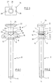
- FIG. 1 The version of a flexible cannula according to the invention shown in Figure 1 consists of a top piece 1 and a tube 2.
- the tube 2 has essentially the shape of a hollow cylinder and can be bevelled at its distal end 4. Attached in the vicinity of its proximal end 6, on the outside of the tube 2 is an annular protrusion 8 with the help of which the tube 2 is secured at the top piece 1.
- the tube 2 is made from a flexible material.
- a housing 10 with a distal end wall 12 and a proximal end wall 14 is joined to the proximal end 6 of the tube 2.
- the distal end wall 12 is provided with an opening which is concentric to the longitudinal axis L-L of the cannula and whose diameter is the same as the diameter of the tube 2.
- An annular recess for housing the protrusion 8 runs round the opening.
- the housing 10 preferably consists of two housing halves which are connected to each other in gas-tight manner, for example glued, so that the assembling of the tube 2 is unproblematical despite the protrusion 8.
- a flexible intermediate tube 16 with an annular protrusion 18 is mounted in the proximal end wall 14, similar to the attachment of the tube 2 to the distal end wall 12.
- the intermediate tube 16 is made from a flexible material and runs concentrically relative to the longitudinal axis L-L. Its internal diameter can be the same as that of the tube 2, but can also be greater.
- the intermediate tube 16 carries a coupling part 22 at its proximal end 20.
- the proximal end face 24 of the coupling part 22 is provided with an opening 26.
- the opening 26 in the proximal end face 24 is essentially aligned with the cross-section surface of the tube 2; the diameter of the opening 26 can be somewhat greater than the internal diameter of the tube 2.
- the opening 26 is surrounded by an annular seal 27 which is made from a flexible plastics material.
- the internal diameter of the seal 27 is preferably smaller than the internal diameter of the tube 2. The result of this is that the seal 27 lies securely against the shaft of an operation instrument introduced through the opening 26, even if the diameter of the shaft should be somewhat smaller than the internal diameter of the tube 2.
- the somewhat greater diameter of the opening 26, acting together with the flexible seal 27, permits a certain mobility for the inserted endoscopic operation instrument.
- the seal could also be designed differently, e.g. as an O-ring arranged further inwards (i.e. displaced in distal direction).
- the coupling elements 28 are designed as two recesses 28, provided with projections, in the wall of the coupling part 22.
- the projections are engaged by corresponding projections at securing clips which are attached to the additional equipment to be fitted, so that a secure mechanical connection results.
- the connection can be released in the usual way by moving the distal end zones of the securing clips with the corresponding projections onto the axis L-L.
- a closure device is arranged in the inside of the housing 10.
- a part of this closure device is a closure sleeve 30.
- the closure sleeve 30 is designed in one piece with the flexible intermediate tube 16 and is thus held via the annular protrusion 18.
- the closure sleeve 30 has the same internal diameter as the flexible intermediate tube 16 and is cut at an angle on both sides, as shown in Figure 1.
- the distal edge of the closure sleeve 30 forms a sealing surface against which two plane plates can lie, the angle between the plates being smaller than 180 degrees, see Figure 1.
- the wings 32 and 33 of a double flap serve as sealing plates.
- a bearing element 34 connected to wing 32 and a bearing element 35 connected to wing 33.
- the ends, designed as trunnions, of the bearing elements 34, 35 are placed in corresponding recesses in side walls 36 and 37 of housing 10, see Figure 2.
- Figure 2 also shows, the length of the wings 32 (hatched in Figure 2) and 33 is great enough to cover the closure sleeve 30 completely, while on the other hand there is enough play in the housing 10 to allow a free swivel movement of the wings 32 and 33.
- the wings 32 and 33 are pressed against the distal edge of the closure sleeve 30 by springs which are not represented in the Figures.
- the distal edge of the closure sleeve 30 can be provided with a seal lining; alternatively, wings 32 and 33 can also be appropriately equipped.
- wings 32 and 33 meet on the longitudinal axis L-L, where they likewise form a sealing surface.
- both bearing elements 34 and 35 can, for example, be guided right through the side wall 36 or 37 on one side (not shown in the Figures) in gas-tight manner. If a lever is attached in each case to the outward-lying ends, wings 32 and 33 can easily be folded away in distal direction. Alternatively, only one of the bearing elements 34 or 35 could be passed through one of the side walls 36 or 37 if the two wings 32 and 33 are so coupled in the inside of the housing 10 that the swivelling of the wing connected to the passed-through bearing element simultaneously effects the swivelling of the other wing.
- the double flap can also be so designed that the wings 32 and 33 come together at an angle of 180 degrees, i.e. that the distal edge of the closure sleeve 30 lies in one plane. The advantage of designing the closure device as a double flap is the small structural height.
- the closure device is a flat slide valve.
- Flat slide valves are known, for example from vacuum technology.
- opening or closure is effected by moving a flat closure part in a direction which runs essentially perpendicular to the axis of the opening to be closed, so that a small structural height is possible in the direction of this axis.
- a flat slide valve cannot be opened directly from the distal end of an operation instrument which is moved essentially along said axis, it must be actuated separately. This can take place manually, for example.
- a usual gas connection with a valve or a manual actuation system for supplying gas into the inside of the body can be provided at the side wall 36 or side wall 37 of the housing 10.
- the tube 2 and the intermediate tube 16 are made from a flexible material suitable for medical purposes, for example silicone or polyurethane.
- the individual parts of the flexible cannula according to the invention are so fitted together that, when the closure device is closed, a space which is sealed off in a gas-tight manner is formed underneath the closure device, which space communicates with its surroundings only via the opening at the distal end 4 of the tube 2.
- a space which is sealed off in a gas-tight manner is formed underneath the closure device, which space communicates with its surroundings only via the opening at the distal end 4 of the tube 2.
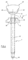
- FIG. 4 shows the inventive flexible cannula according to the described embodiment together with an introduced trocar 40.
- the trocar 40 has a shaft 42 whose external diameter corresponds to the internal diameter of the tube 2 or is somewhat smaller. At its distal end, the shaft 42 carries a trocar point 44 with the help of which a puncture point is produced in the body wall. Attached to the proximal end of the shaft 42 is a handling part 46 which serves to advance the trocar point 44. Attached to the handling part 46 and serving as coupling elements are two securing clips which can be pressed inwards with the help of two push buttons 48 in order to release the connection, as described earlier.
- the tube is made from a flexible material and the top piece is designed flat when seen in the direction of the longitudinal axis of the cannula.
- the top piece is not divided into several components as in the previous embodiment, but both the closure device and the opening at the proximal end face with the associated seal and the coupling elements are integrated in a single housing which is attached to the proximal end of the tube.
- the closure device can be designed for example as a space-saving double flap of the type described above or as a flat slide valve. Because of the small extension of the top piece in the direction of the longitudinal axis of the cannula, the introduction of a bent operation instrument is not impeded, although the top piece itself is rigid.
Landscapes
- Health & Medical Sciences (AREA)
- Life Sciences & Earth Sciences (AREA)
- Animal Behavior & Ethology (AREA)
- Veterinary Medicine (AREA)
- Public Health (AREA)
- Surgery (AREA)
- General Health & Medical Sciences (AREA)
- Engineering & Computer Science (AREA)
- Medical Informatics (AREA)
- Molecular Biology (AREA)
- Heart & Thoracic Surgery (AREA)
- Biomedical Technology (AREA)
- Nuclear Medicine, Radiotherapy & Molecular Imaging (AREA)
- Pathology (AREA)
- Chemical & Material Sciences (AREA)
- Chemical Kinetics & Catalysis (AREA)
- Epidemiology (AREA)
- Surgical Instruments (AREA)
- Endoscopes (AREA)
- Materials For Medical Uses (AREA)
Applications Claiming Priority (2)
| Application Number | Priority Date | Filing Date | Title |
|---|---|---|---|
| DE4234990 | 1992-10-16 | ||
| DE4234990A DE4234990C2 (de) | 1992-10-16 | 1992-10-16 | Trokarhülse |
Publications (3)
| Publication Number | Publication Date |
|---|---|
| EP0598461A2 EP0598461A2 (en) | 1994-05-25 |
| EP0598461A3 EP0598461A3 (enExample) | 1994-08-31 |
| EP0598461B1 true EP0598461B1 (en) | 1996-02-21 |
Family
ID=6470671
Family Applications (1)
| Application Number | Title | Priority Date | Filing Date |
|---|---|---|---|
| EP93250272A Expired - Lifetime EP0598461B1 (en) | 1992-10-16 | 1993-10-07 | Flexible cannula |
Country Status (7)
| Country | Link |
|---|---|
| US (1) | US5383861A (enExample) |
| EP (1) | EP0598461B1 (enExample) |
| JP (1) | JPH0739552A (enExample) |
| AT (1) | ATE134310T1 (enExample) |
| CA (1) | CA2108385A1 (enExample) |
| DE (2) | DE4234990C2 (enExample) |
| IL (1) | IL107270A0 (enExample) |
Families Citing this family (60)
| Publication number | Priority date | Publication date | Assignee | Title |
|---|---|---|---|---|
| US6572631B1 (en) * | 1993-10-22 | 2003-06-03 | Gynetech Pty Ltd. | Transvaginal tube as an aid to laparoscopic surgery |
| USD362066S (en) | 1994-11-04 | 1995-09-05 | Marlow Surgical Technologies, Inc. | Disposable surgical trocar |
| DE69735146T2 (de) * | 1996-05-09 | 2006-09-28 | Olympus Corporation | Chirurgisches Werkzeug zum Halten eines Hohlraums |
| JP3244645B2 (ja) * | 1997-05-07 | 2002-01-07 | 旭光学工業株式会社 | 内視鏡下外科手術用処置具 |
| US7998068B2 (en) | 1998-12-01 | 2011-08-16 | Atropos Limited | Instrument access device |
| US7559893B2 (en) | 1998-12-01 | 2009-07-14 | Atropos Limited | Wound retractor device |
| US7537564B2 (en) | 1998-12-01 | 2009-05-26 | Atropos Limited | Wound retractor device |
| IE991010A1 (en) * | 1998-12-01 | 2000-07-12 | Atropos Ltd | A Device |
| ATE397416T1 (de) * | 1998-12-01 | 2008-06-15 | Atropos Ltd | Chirurgischer wundretraktor |
| ES2316389T3 (es) | 1999-10-14 | 2009-04-16 | Atropos Limited | Retractor de herida. |
| US7540839B2 (en) * | 1999-10-14 | 2009-06-02 | Atropos Limited | Wound retractor |
| EP1303222A1 (en) * | 2000-07-21 | 2003-04-23 | Atropos Limited | A cannula |
| WO2002007611A2 (en) * | 2000-07-21 | 2002-01-31 | Atropos Limited | A surgical instrument |
| JP5190169B2 (ja) | 2000-10-19 | 2013-04-24 | アプライド メディカル リソーシーズ コーポレイション | 外科用接近器具及び方法 |
| WO2003015848A1 (en) | 2001-08-14 | 2003-02-27 | Applied Medical Resources Corporation | Access sealing apparatus and method |
| US6958037B2 (en) | 2001-10-20 | 2005-10-25 | Applied Medical Resources Corporation | Wound retraction apparatus and method |
| EP1534201B1 (en) | 2002-06-05 | 2011-05-25 | Applied Medical Resources Corporation | Wound retractor |
| US9271753B2 (en) | 2002-08-08 | 2016-03-01 | Atropos Limited | Surgical device |
| DE60314464T2 (de) * | 2002-09-19 | 2008-02-14 | Atropos Ltd., Bray | Chirurgischer wundretraktor |
| DE60315188T2 (de) * | 2002-12-16 | 2008-04-03 | Atropos Ltd., Bray | Chirurgische vorrichtung |
| US20050020884A1 (en) | 2003-02-25 | 2005-01-27 | Hart Charles C. | Surgical access system |
| MXPA06001219A (es) * | 2003-07-30 | 2006-08-31 | Atropos Ltd | Un dispositivo quirurgico. |
| AU2004263142A1 (en) | 2003-08-06 | 2005-02-17 | Applied Medical Resources Corporation | Surgical device with tack-free gel and method of manufacture |
| US7163510B2 (en) * | 2003-09-17 | 2007-01-16 | Applied Medical Resources Corporation | Surgical instrument access device |
| US20060161050A1 (en) * | 2003-10-15 | 2006-07-20 | John Butler | A surgical sealing device |
| EP1677683A2 (en) * | 2003-10-15 | 2006-07-12 | Atropos Limited | A surgical sealing device |
| JP4832763B2 (ja) * | 2004-01-20 | 2011-12-07 | エシコン・エンド−サージェリィ・インコーポレイテッド | アクセス用医療装置および医療処置実行方法 |
| US20070185003A1 (en) * | 2006-01-18 | 2007-08-09 | Invista North America S.A.R.L. | Non-textile polymer compositions and methods |
| US20070010823A1 (en) * | 2005-07-11 | 2007-01-11 | Cannuflow, Inc. | Arthroscopic shaver system |
| JP2009501045A (ja) | 2005-07-15 | 2009-01-15 | アトロポス・リミテッド | 創傷レトラクタ |
| JP4927852B2 (ja) * | 2005-10-14 | 2012-05-09 | アプライド メディカル リソーシーズ コーポレイション | ゲルパッドを備えた割り型フープ開創器 |
| US7866021B2 (en) * | 2006-05-31 | 2011-01-11 | Jac Property Holdings, Llc | Methods and assemblies for manufacturing components |
| US7798998B2 (en) | 2006-10-06 | 2010-09-21 | Surgiquest, Inc. | Elastically deformable surgical access device |
| US7806870B2 (en) * | 2006-10-06 | 2010-10-05 | Surgiquest, Incorporated | Elastically deformable surgical access device having telescoping guide tube |
| US8795235B2 (en) * | 2006-10-06 | 2014-08-05 | Surgiquest, Inc. | Devices for and methods of performing minimally-invasive surgical procedures through a single incision |
| US7963431B2 (en) * | 2006-10-06 | 2011-06-21 | Tyco Healthcare Group, Lp | Grasping jaw mechanism |
| WO2008141291A1 (en) | 2007-05-11 | 2008-11-20 | Applied Medical Resources Corporation | Surgical retractor with gel pad |
| AU2008251314B2 (en) * | 2007-05-11 | 2013-05-02 | Applied Medical Resources Corporation | Surgical retractor |
| EP2152175B1 (en) | 2007-06-05 | 2015-10-28 | Atropos Limited | An instrument access device |
| US20110071359A1 (en) | 2007-06-05 | 2011-03-24 | Frank Bonadio | Instrument Access Device |
| US8657740B2 (en) * | 2007-06-05 | 2014-02-25 | Atropos Limited | Instrument access device |
| WO2009024955A1 (en) * | 2007-08-20 | 2009-02-26 | Atropos Limited | A hand and instrument access device |
| AU2009206407B2 (en) | 2008-01-22 | 2014-04-24 | Applied Medical Resources Corporation | Surgical instrument access device |
| WO2010045253A1 (en) * | 2008-10-13 | 2010-04-22 | Applied Medical Resources Corporation | Single port access system |
| US20110264136A1 (en) * | 2008-12-12 | 2011-10-27 | Seung Wook Choi | Surgical instrument |
| US8375955B2 (en) | 2009-02-06 | 2013-02-19 | Atropos Limited | Surgical procedure |
| JP5482100B2 (ja) * | 2009-10-28 | 2014-04-23 | 東洋製罐株式会社 | 金属缶用印刷フィルム、その製造方法及び製造装置 |
| CA2811753C (en) | 2010-10-01 | 2019-05-21 | Applied Medical Resources Corporation | Natural orifice surgery system |
| US9289115B2 (en) | 2010-10-01 | 2016-03-22 | Applied Medical Resources Corporation | Natural orifice surgery system |
| KR102423785B1 (ko) | 2011-05-10 | 2022-07-21 | 어플라이드 메디컬 리소시스 코포레이션 | 창상 견인기 |
| ES2989097T3 (es) | 2013-03-15 | 2024-11-25 | Applied Med Resources | Dispositivo mecánico de gel para acceso quirúrgico |
| CA2952640C (en) | 2014-07-18 | 2023-04-04 | Applied Medical Resources Corporation | Gels having permanent tack free coatings and method of manufacture |
| EP4101405B1 (en) | 2014-08-15 | 2025-04-02 | Applied Medical Resources Corporation | Natural orifice surgery system |
| EP2992843A1 (en) * | 2014-09-04 | 2016-03-09 | Prometheus Delta Tech Limited | A transcutaneous device for removal of fluid from a body |
| KR20170091657A (ko) | 2014-11-25 | 2017-08-09 | 어플라이드 메디컬 리소시스 코포레이션 | 지지 및 가이던스 구조체들을 이용한 원주방향 상처 견인 |
| EP3349675B1 (en) | 2015-09-15 | 2020-10-21 | Applied Medical Resources Corporation | Surgical robotic access system |
| WO2017062850A2 (en) | 2015-10-07 | 2017-04-13 | Applied Medical Resources Corporation | Wound retractor with multi-segment outer ring |
| DE102016101462B4 (de) | 2016-01-27 | 2019-01-17 | Karl Storz Se & Co. Kg | Trokarhülse, Trokarsystem sowie Verfahren zur Herstellung einer Trokarhülse |
| ES3038451T3 (en) | 2016-09-12 | 2025-10-13 | Applied Med Resources | Surgical robotic access system for irregularly shaped robotic actuators and associated robotic surgical instruments |
| JP2023550877A (ja) * | 2020-10-26 | 2023-12-06 | パティル・アダーシュ・マラゴーダ | ポイントオブケアで患者の腹膜腔を直接視覚化するための携帯型使い捨てマイクロ腹腔鏡 |
Family Cites Families (22)
| Publication number | Priority date | Publication date | Assignee | Title |
|---|---|---|---|---|
| DE7430345U (de) * | 1974-12-12 | Richard Wolf Gmbh | Trokarhülse für die Endoskopie von Körperhöhlen | |
| US3915168A (en) * | 1973-03-07 | 1975-10-28 | Bard Inc C R | Intravenous catheter introduction assembly |
| US4000739A (en) * | 1975-07-09 | 1977-01-04 | Cordis Corporation | Hemostasis cannula |
| US4368730A (en) * | 1981-02-12 | 1983-01-18 | Nigel Sharrock | Intravenous catheter |
| US4447235A (en) * | 1981-05-07 | 1984-05-08 | John M. Clarke | Thoracentesis device |
| US4424833A (en) * | 1981-10-02 | 1984-01-10 | C. R. Bard, Inc. | Self sealing gasket assembly |
| US4535773A (en) * | 1982-03-26 | 1985-08-20 | Inbae Yoon | Safety puncturing instrument and method |
| US5308336A (en) * | 1982-09-28 | 1994-05-03 | Applied Medical Resources | Seal protection mechanism |
| US4634432A (en) * | 1985-05-13 | 1987-01-06 | Nuri Kocak | Introducer sheath assembly |
| US5053016A (en) * | 1987-12-31 | 1991-10-01 | United States Surgical Corporation | Valve seat for an insufflation cannula assembly |
| US5129885A (en) * | 1990-02-13 | 1992-07-14 | United States Surgical Corporation | Safety device for trocars and surgical instruments therefor |
| US4960412A (en) * | 1988-04-15 | 1990-10-02 | Universal Medical Instrument Corp. | Catheter introducing system |
| DE8914955U1 (de) * | 1989-12-18 | 1990-05-03 | Wisap Gesellschaft für wissenschaftlichen Apparatebau mbH, 8029 Sauerlach | Trokarhülse |
| US5114407A (en) * | 1990-08-30 | 1992-05-19 | Ethicon, Inc. | Safety mechanism for trocar |
| US5147316A (en) * | 1990-11-19 | 1992-09-15 | Castillenti Thomas A | Laparoscopic trocar with self-locking port sleeve |
| US5226426A (en) * | 1990-12-18 | 1993-07-13 | Inbae Yoon | Safety penetrating instrument |
| US5125903A (en) * | 1991-08-01 | 1992-06-30 | Medtronic, Inc. | Hemostasis valve |
| US5141498A (en) * | 1991-09-10 | 1992-08-25 | Unisurge, Incorporated | Flexible valve and device incorporating the same |
| EP0535974A1 (en) * | 1991-10-04 | 1993-04-07 | Ethicon, Inc. | Flexible trocar tube |
| US5242412A (en) * | 1992-01-21 | 1993-09-07 | Blake Joseph W Iii | Trocar tube subassembly having sealing ring and duckbill sealing tube having planar, truncate, diverging sealing bills |
| US5201714A (en) * | 1992-03-05 | 1993-04-13 | Conmed Corporation | Laparoscopic cannula |
| US5226891A (en) * | 1992-04-07 | 1993-07-13 | Applied Medical Resources | Seal protection apparatus |
-
1992
- 1992-10-16 DE DE4234990A patent/DE4234990C2/de not_active Expired - Lifetime
-
1993
- 1993-10-07 AT AT93250272T patent/ATE134310T1/de not_active IP Right Cessation
- 1993-10-07 EP EP93250272A patent/EP0598461B1/en not_active Expired - Lifetime
- 1993-10-07 DE DE69301598T patent/DE69301598T2/de not_active Expired - Lifetime
- 1993-10-12 US US08/135,216 patent/US5383861A/en not_active Expired - Lifetime
- 1993-10-13 JP JP5278914A patent/JPH0739552A/ja active Pending
- 1993-10-13 IL IL107270A patent/IL107270A0/xx unknown
- 1993-10-14 CA CA002108385A patent/CA2108385A1/en not_active Abandoned
Also Published As
| Publication number | Publication date |
|---|---|
| EP0598461A3 (enExample) | 1994-08-31 |
| DE4234990A1 (de) | 1994-04-21 |
| DE69301598T2 (de) | 1996-07-11 |
| CA2108385A1 (en) | 1994-04-17 |
| DE4234990C2 (de) | 1995-02-16 |
| ATE134310T1 (de) | 1996-03-15 |
| JPH0739552A (ja) | 1995-02-10 |
| IL107270A0 (en) | 1994-01-25 |
| EP0598461A2 (en) | 1994-05-25 |
| DE69301598D1 (de) | 1996-03-28 |
| US5383861A (en) | 1995-01-24 |
Similar Documents
| Publication | Publication Date | Title |
|---|---|---|
| EP0598461B1 (en) | Flexible cannula | |
| US5820604A (en) | Cannula cap including yeildable outer seal and flapper valve | |
| US6066117A (en) | Cannula flapper valve assembly | |
| EP1127550B1 (en) | Apparatus for introducing an instrument into the body of a patient | |
| US5385560A (en) | Reducer for cannulae | |
| JP4184403B2 (ja) | 細長い物体をシールした状態で受け入れるための弁組立体 | |
| JP3626188B2 (ja) | 導管コネクター用キャップ装置 | |
| US5221264A (en) | Reduction port for laparoscopic trocar sleeve and related method | |
| EP1035804B1 (en) | Seal member for surgical trocar | |
| CA2410677C (en) | Trocar assembly | |
| US7632250B2 (en) | Introducer seal assembly | |
| EP1745810B1 (en) | Trocar seal system | |
| KR100813755B1 (ko) | 의료용 처치 용구 | |
| CA2560158C (en) | Surgical hand access apparatus | |
| JP3549554B2 (ja) | 手術用カニューレのアダプタシール | |
| US20050209608A1 (en) | Trocar seal | |
| EP2233090A1 (en) | Articulating surgical portal apparatus with spring | |
| WO1995007056A3 (en) | Apparatus for use in surgery and a valve | |
| EP2266481B1 (en) | Access assembly with flexible housing |
Legal Events
| Date | Code | Title | Description |
|---|---|---|---|
| PUAI | Public reference made under article 153(3) epc to a published international application that has entered the european phase |
Free format text: ORIGINAL CODE: 0009012 |
|
| AK | Designated contracting states |
Kind code of ref document: A2 Designated state(s): AT BE CH DE ES GB IE LI LU NL PT SE |
|
| PUAL | Search report despatched |
Free format text: ORIGINAL CODE: 0009013 |
|
| AK | Designated contracting states |
Kind code of ref document: A3 Designated state(s): AT BE CH DE ES GB IE LI LU NL PT SE |
|
| 17P | Request for examination filed |
Effective date: 19941219 |
|
| 17Q | First examination report despatched |
Effective date: 19950524 |
|
| GRAA | (expected) grant |
Free format text: ORIGINAL CODE: 0009210 |
|
| AK | Designated contracting states |
Kind code of ref document: B1 Designated state(s): AT BE CH DE ES GB IE LI LU NL PT SE |
|
| PG25 | Lapsed in a contracting state [announced via postgrant information from national office to epo] |
Ref country code: NL Free format text: LAPSE BECAUSE OF FAILURE TO SUBMIT A TRANSLATION OF THE DESCRIPTION OR TO PAY THE FEE WITHIN THE PRESCRIBED TIME-LIMIT Effective date: 19960221 |
|
| REF | Corresponds to: |
Ref document number: 134310 Country of ref document: AT Date of ref document: 19960315 Kind code of ref document: T |
|
| REG | Reference to a national code |
Ref country code: IE Ref legal event code: FG4D Free format text: 67307 |
|
| REF | Corresponds to: |
Ref document number: 69301598 Country of ref document: DE Date of ref document: 19960328 |
|
| REG | Reference to a national code |
Ref country code: CH Ref legal event code: NV Representative=s name: E. BLUM & CO. PATENTANWAELTE |
|
| PG25 | Lapsed in a contracting state [announced via postgrant information from national office to epo] |
Ref country code: SE Effective date: 19960521 Ref country code: PT Effective date: 19960521 |
|
| PG25 | Lapsed in a contracting state [announced via postgrant information from national office to epo] |
Ref country code: ES Free format text: LAPSE BECAUSE OF FAILURE TO SUBMIT A TRANSLATION OF THE DESCRIPTION OR TO PAY THE FEE WITHIN THE PRESCRIBED TIME-LIMIT Effective date: 19960601 |
|
| NLV1 | Nl: lapsed or annulled due to failure to fulfill the requirements of art. 29p and 29m of the patents act | ||
| PLBE | No opposition filed within time limit |
Free format text: ORIGINAL CODE: 0009261 |
|
| 26N | No opposition filed | ||
| PGFP | Annual fee paid to national office [announced via postgrant information from national office to epo] |
Ref country code: ES Payment date: 19971017 Year of fee payment: 5 |
|
| REG | Reference to a national code |
Ref country code: GB Ref legal event code: IF02 |
|
| REG | Reference to a national code |
Ref country code: CH Ref legal event code: PFA Owner name: ETHICON INC. Free format text: ETHICON INC.#ROUTE 22#SOMERVILLE, NEW JERSEY 08876-0151 (US) -TRANSFER TO- ETHICON INC.#ROUTE 22#SOMERVILLE, NEW JERSEY 08876-0151 (US) |
|
| PGFP | Annual fee paid to national office [announced via postgrant information from national office to epo] |
Ref country code: LU Payment date: 20081016 Year of fee payment: 16 Ref country code: IE Payment date: 20081015 Year of fee payment: 16 Ref country code: CH Payment date: 20081016 Year of fee payment: 16 |
|
| PGFP | Annual fee paid to national office [announced via postgrant information from national office to epo] |
Ref country code: AT Payment date: 20081013 Year of fee payment: 16 |
|
| PGFP | Annual fee paid to national office [announced via postgrant information from national office to epo] |
Ref country code: BE Payment date: 20081009 Year of fee payment: 16 |
|
| PGFP | Annual fee paid to national office [announced via postgrant information from national office to epo] |
Ref country code: GB Payment date: 20081001 Year of fee payment: 16 |
|
| BERE | Be: lapsed |
Owner name: *ETHICON INC. Effective date: 20091031 |
|
| REG | Reference to a national code |
Ref country code: CH Ref legal event code: PL |
|
| REG | Reference to a national code |
Ref country code: IE Ref legal event code: MM4A |
|
| PG25 | Lapsed in a contracting state [announced via postgrant information from national office to epo] |
Ref country code: AT Free format text: LAPSE BECAUSE OF NON-PAYMENT OF DUE FEES Effective date: 20091007 |
|
| PG25 | Lapsed in a contracting state [announced via postgrant information from national office to epo] |
Ref country code: LI Free format text: LAPSE BECAUSE OF NON-PAYMENT OF DUE FEES Effective date: 20091031 Ref country code: IE Free format text: LAPSE BECAUSE OF NON-PAYMENT OF DUE FEES Effective date: 20091007 Ref country code: CH Free format text: LAPSE BECAUSE OF NON-PAYMENT OF DUE FEES Effective date: 20091031 Ref country code: BE Free format text: LAPSE BECAUSE OF NON-PAYMENT OF DUE FEES Effective date: 20091031 |
|
| PG25 | Lapsed in a contracting state [announced via postgrant information from national office to epo] |
Ref country code: GB Free format text: LAPSE BECAUSE OF NON-PAYMENT OF DUE FEES Effective date: 20091007 |
|
| PG25 | Lapsed in a contracting state [announced via postgrant information from national office to epo] |
Ref country code: LU Free format text: LAPSE BECAUSE OF NON-PAYMENT OF DUE FEES Effective date: 20091007 |
|
| PGFP | Annual fee paid to national office [announced via postgrant information from national office to epo] |
Ref country code: DE Payment date: 20121003 Year of fee payment: 20 |
|
| REG | Reference to a national code |
Ref country code: DE Ref legal event code: R071 Ref document number: 69301598 Country of ref document: DE |
|
| PG25 | Lapsed in a contracting state [announced via postgrant information from national office to epo] |
Ref country code: DE Free format text: LAPSE BECAUSE OF EXPIRATION OF PROTECTION Effective date: 20131008 |