EP0597922B1 - System zur Geschwindigkeitsregelung mit variabler Verstärkung in Abhängigkeit der Geschwindigkeitsabweichung - Google Patents
System zur Geschwindigkeitsregelung mit variabler Verstärkung in Abhängigkeit der Geschwindigkeitsabweichung Download PDFInfo
- Publication number
- EP0597922B1 EP0597922B1 EP92916214A EP92916214A EP0597922B1 EP 0597922 B1 EP0597922 B1 EP 0597922B1 EP 92916214 A EP92916214 A EP 92916214A EP 92916214 A EP92916214 A EP 92916214A EP 0597922 B1 EP0597922 B1 EP 0597922B1
- Authority
- EP
- European Patent Office
- Prior art keywords
- speed
- error signal
- linear function
- signal
- correction
- Prior art date
- Legal status (The legal status is an assumption and is not a legal conclusion. Google has not performed a legal analysis and makes no representation as to the accuracy of the status listed.)
- Expired - Lifetime
Links
Images


Classifications
-
- B—PERFORMING OPERATIONS; TRANSPORTING
- B60—VEHICLES IN GENERAL
- B60K—ARRANGEMENT OR MOUNTING OF PROPULSION UNITS OR OF TRANSMISSIONS IN VEHICLES; ARRANGEMENT OR MOUNTING OF PLURAL DIVERSE PRIME-MOVERS IN VEHICLES; AUXILIARY DRIVES FOR VEHICLES; INSTRUMENTATION OR DASHBOARDS FOR VEHICLES; ARRANGEMENTS IN CONNECTION WITH COOLING, AIR INTAKE, GAS EXHAUST OR FUEL SUPPLY OF PROPULSION UNITS IN VEHICLES
- B60K31/00—Vehicle fittings, acting on a single sub-unit only, for automatically controlling vehicle speed, i.e. preventing speed from exceeding an arbitrarily established velocity or maintaining speed at a particular velocity, as selected by the vehicle operator
-
- B—PERFORMING OPERATIONS; TRANSPORTING
- B60—VEHICLES IN GENERAL
- B60W—CONJOINT CONTROL OF VEHICLE SUB-UNITS OF DIFFERENT TYPE OR DIFFERENT FUNCTION; CONTROL SYSTEMS SPECIALLY ADAPTED FOR HYBRID VEHICLES; ROAD VEHICLE DRIVE CONTROL SYSTEMS FOR PURPOSES NOT RELATED TO THE CONTROL OF A PARTICULAR SUB-UNIT
- B60W50/00—Details of control systems for road vehicle drive control not related to the control of a particular sub-unit, e.g. process diagnostic or vehicle driver interfaces
- B60W2050/0001—Details of the control system
- B60W2050/0019—Control system elements or transfer functions
- B60W2050/0022—Gains, weighting coefficients or weighting functions
-
- B—PERFORMING OPERATIONS; TRANSPORTING
- B60—VEHICLES IN GENERAL
- B60W—CONJOINT CONTROL OF VEHICLE SUB-UNITS OF DIFFERENT TYPE OR DIFFERENT FUNCTION; CONTROL SYSTEMS SPECIALLY ADAPTED FOR HYBRID VEHICLES; ROAD VEHICLE DRIVE CONTROL SYSTEMS FOR PURPOSES NOT RELATED TO THE CONTROL OF A PARTICULAR SUB-UNIT
- B60W2710/00—Output or target parameters relating to a particular sub-units
- B60W2710/06—Combustion engines, Gas turbines
- B60W2710/0605—Throttle position
Definitions
- the field of the invention relates to speed control systems for motor vehicles.
- Speed control systems are known which control the engine throttle in response to a difference between vehicle speed and a reference speed. Many of such speed control systems amplify this difference signal by a gain constant.
- prior speed control systems do not appear to distinguish between operation while cruising over a relatively flat super highway or encountering a sudden gradient. Accordingly, speed control operation may appear to be hunting on flat surfaces, drooping when encountering uphill gradients and overshooting when traversing downhill.
- DE-A-3 841 386 An example of a prior art approach is represented by DE-A-3 841 386.
- a speed control system for a vehicle in which the throttle is controlled so as to maintain the vehicle at a desired speed.
- the system includes means to sense the actual vehicle speed and to compare this actual speed with the desired speed to generate an error signal.
- a control signal for the throttle is derived from the error signal through a variable amplifying arrangement which operates on the error signal in dependence upon the loading of the vehicle.
- An object of the invention is to provide a speed control system with variable gains related to the speed error such that stable speed control operation is achieved over a wide variation of road conditions.
- a speed control method controlling the engine throttle to maintain vehicle speed at a desired speed, comprising the steps of; comparing the vehicle speed to the desired speed to generate an error signal; generating a correction signal related to said error signal and multiplying said correction signal by an adjustable gain value; and actuating the engine throttle in relation to the multiplication of the correction signal by the adjustable gain value; characterised in that the method further comprises; providing the adjustable gain value with a variable amplitude generated as a linear function of said error signal, said variable amplitude being a first linear function of said error signal when said error signal is less than a predetermined amplitude and a second linear function when said error signal exceeds said predetermined amplitude, said second linear function being different from said first linear function.
- An advantage of the invention is that low gain values are provided for small speed errors such that speed hunting which was indicative of some prior approaches, on relatively flat road surfaces is avoided. Another advantage is provided by having gain values with greater gains at higher speed errors, such that more rapid speed control response is provided when encountering a road gradient. Accordingly, speed droop when encountering an uphill gradient is avoided as is speed overshoot when encountering a downhill gradient. Still another advantage is provided of rapidly correcting for road gradients by increasing the linear relationship between gain values and speed error when speed error exceeds a preselected threshold. In addition, different linear relationships are selectable for positive and negative speed errors to specifically compensate for vehicle response. An additional advantage is thereby achieved of compensating for variations in vehicle response which are related to speed error sign.
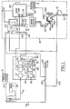
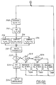
- Speed control system 10 is first described in general terms with reference to the block diagram shown in Figure 1. More detailed description is provided later herein with particular reference to Figures 2-16.
- Speed control system 10 controls the engine throttle (not shown) via cable drum 12, connected to throttle cable 14.
- speed control system 10 is responsive to: vehicle speed sensor 18 which is described in greater detail in U.S. Patent Application Serial No. 280,907, the specification of which is incorporated herein by reference; brake light switch 24; and brake dump switch 26 which is responsive to a predetermined hydraulic fluid pressure in the brake line such as, for example, 100 psi.
- the above inputs are filtered and buffered in a conventional manner by input signal conditioning circuitry 28.
- speed control system 10 is responsive to multiplex switch assembly 30 mounted on the vehicle steering wheel (not shown).
- multiplex switch assembly 30 includes the following operator actuable momentary switches: ON/OFF switch 32, COAST switch 34, SET/ACCEL switch 36, and RESUME/CANCEL switch 38.
- Microcomputer 42 a conventional microcomputer such as the 6805 series, is shown responsive to the above described inputs for controlling stepper motor 50 which in turn controls cable drum 12 via reduction gearing 54 and electromagnetic clutch 56.
- electromagnetic clutch 56 includes clutch plates 58a and 58b wherein clutch plate 58b is displaced against a return spring (not shown) in response to the flow of electrical current through coil 60.
- coil 60 is shown having one end connected to an electrical ground via clutch driver 64, a field effect transistor in this particular example, which is responsive to microcomputer 42.
- the other end of coil 60 is coupled to battery power V B via brake dump switch 26.
- microcomputer 42 instructs stepper motor 50 to turn to an idle position and thereafter opens electromagnetic clutch 56 via clutch driver 64.
- electromagnetic clutch 56 becomes immediately disengaged upon actuation of brake dump switch 26 when a predetermined pressure is achieved in the brake system.
- multiplex switch assembly 30 receives electrical power (V B ') at node 64 via the relay coil of electrical horn assembly 66 through slip ring 70. Electrical ground is shown received at node 72 of multiplex switch assembly 30 via slip ring 74.
- Switch assembly 30 includes output node 80 which is coupled to node 82 of bridge circuit 86 via slip ring 88.
- a multiplexed output signal or voltage is provided at node 80 by multiplex switch assembly 30.
- Microcomputer 42 decodes the multiplexed output signal to provide the appropriate command signals. In this particular example, one of five preselected voltages is provided at node 82 (V82) by actuation of either momentary switch 32, 34, 36, or 38.
- ON/OFF switch 32 is shown as a single pole double throw momentary switch having its pole connected to node 80, its "ON" position connected to node 64, and its "OFF” position connected to electrical ground at node 72.
- COAST switch 34 is shown as a momentary switch connected in series with resistor 94 between node 80 and node 72.
- SET/ACCEL switch 36 is shown as a momentary switch connected in series with resistor 96 between node 80 and node 72.
- RESUME/CANCEL switch 38 is shown as a momentary switch connected in series with resistor 98 between node 80 and node 72.
- Horn switch 92 is connected in series between nodes 64 and 74.
- Electrical bridge 86 is shown including two resistive voltage dividers coupled between electrical ground and node 102 which in turn is coupled to V B .
- the first voltage divider includes resistor 114 (R114) coupled between node 102 and node 82, and resistor 116 (R116) coupled between electrical ground and node 82.
- the second resistive voltage divider includes resistor 120 (R120) and resistor 122 (R122) interconnected with node 104. Nodes 82 and 104 are shown connected to respective A/D inputs A/D1 and A/D2 of microcomputer 42.
- resistor 94 is coupled in parallel with resistor 116 of electrical bridge 86. Accordingly, the voltage at node 82 during depression of COAST switch 34 is represented by: V B * ⁇ R116 R94/(R114 + ⁇ R116 R94); where ⁇ R116 R94 represents the resistance of the parallel combination of R116 and R94.
- resistor 96 While SET/ACCEL switch 36 is held in the depressed position, resistor 96 is coupled in parallel with resistor 116. During such momentary depression, the voltage at node 82 is represented by: V B * ⁇ R116 R96/(R114 + ⁇ R116 R96).
- resistor 98 is coupled in parallel with resistor 116.
- the voltage at node 82 is then represented by: V B * ⁇ R116 R98/(R114 + ⁇ R116 R98).
- the voltage at node 104 (V104) of bridge 86 is a system reference voltage determined by dividing V B by the second resistive voltage divider including resistors 120 and 122 (i.e., V B * R120/R120 + R122). Any variation in battery voltage, voltage transients or noise on the voltage line will affect both V82 and V104 in a proportionate manner. As described below with reference to Figures 2A-2B, microcomputer 42 scales V82 by V104 to cancel the effects of voltage variations and noise from V82.
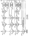
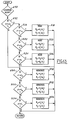
- microcomputer 42 in decoding multiplex switch assembly 30, and providing speed control commands is now described with reference to the flowchart shown in Figures 2A-2B.
- Each block shown is representative of process steps performed by microcomputer 42 during each of its background loops.
- the process shown may be performed by other components such as analog circuitry or discrete logic components commonly referred to as Integrated Circuits.
- step 152 the brake light signal is sampled in step 152.
- the Brake Flag is set and the STANDBY COMMAND generated (see steps 154 and 156).
- stepper motor 50 is phase stepped to an idle throttle position and electromagnetic clutch 56 then opened. Thereafter, resumption of speed control operation occurs with either a SET COMMAND or a RESUME COMMAND.
- step 158 compares actual vehicle speed (v) to preselected range around reference speed ms which is stored in memory. When vehicle speed is beyond this preselected range, a STANDBY COMMAND is generated (steps 156 and 158). When vehicle speed is within the preselected range, the digital representation of V82 and V104 is sampled during step 162. Command signal V c is then generated in step 164 by scaling V82 with V104 to eliminate the effects of voltage variations and noise at node 82 as previously described herein. Accordingly, command signal V c is a digital representation or coding of V82 which in turn is a voltage representation of switch actuation in multiplex switch assembly 30.
- an ON Flag is set and the ON COMMAND generated when the digital representation of V82 is greater than V104. Stated another way, speed control operation is enabled when the above comparison indicates that ON/OFF Switch 32 is momentary actuated in the ON position.
- V c is then compared to a digital representation of the voltage, or voltage range, associated with momentary actuation of ON/OFF switch 32 in the OFF position (V OFF ) during step 176. If V c is equal to V OFF , the ON Flag is cleared and the OFF COMMAND generated during steps 178 and 180. Stepper motor 50 is then sequenced to an idle position and electromagnetic clutch assembly 56 opened. Speed control operation cannot thereafter be reactuated until an ON COMMAND is received.
- command signal V c is compared to signal V Set which is a digital representation of the voltage at node 82 during actuation of SET/ACCEL switch 36 (see step 186). If command signal V c and signal V Set are equal, the previous state of signal V c is then checked for an idle switch condition (V Idle ) corresponding to concurrent deactuation of all momentary switches in multiplex switch assembly 30 (see step 188). Should the previous state be other than an idle switch position, two switches may be concurrently actuated by the operator, in which case further speed control processing is exited.
- V Idle idle switch condition
- step 186 If command signal V c is equal to V Set (see step 186), and the previous state of command signal V c was at an idle position (see step 188) indicating that all switches were previously deactuated, then the Brake Flag is checked during step 190. It is noted that the Brake Flag is set during application of the vehicular brakes (see steps 150 and 152) and cleared when command signal V c is detected at an idle position indicating that all momentary switches were concurrently deactuated (see steps 230 and 232).
- command signal V c is checked to see if it was also at V Set during the previous background loop. If it was not, then a SET COMMAND is generated (see steps 192 and 194). On the other hand, if command signal V c was also at V Set during the previous background loop, an ACCEL COMMAND is generated (see steps 192 and 196). Stated another way, detection of continued depression of SET/ACCEL switch 36 results in an ACCEL COMMAND.
- the SET COMMAND begins initialising speed control operation to achieve the vehicle speed present at the time SET/ACCEL switch 36 is depressed. During continued depression of the switch, speed control system 10 accelerates the vehicle by incrementing the set speed in a preprogrammed manner.
- Decoding the actuation of COAST switch 34 occurs during process step 200.
- V Idle the digital representation of the voltage at node 82 associated with such actuation is detected
- V c the previous state of command signal V c is checked in step 202.
- a COAST COMMAND is generated. Otherwise, processing for the particular background loop ceases.
- stepper motor 50 is turned to idle. Release of COAST switch 34 results in reinitialising speed control operation at the vehicle speed which occurred at the time of such release.
- Decoding actuation of RESUME/CANCEL switch 38 and subsequent generation of the RESUME COMMAND begins with step 210.
- the previous state of command signal V c is checked for an idle condition during step 212. If all switches were previously deactuated and the Brake Flag is in the cleared state (see step 214), the Standby Mode is then checked during (see step 216). If previously in the Standby Mode, the RESUME COMMAND is then generated during step 218. However, if speed control was not previously in the Standby Mode (i.e., speed control in control mode), then depression of RESUME/CANCEL switch 38 is interpreted as a Cancel and the Standby Mode generated (step 220).
- speed control operation is prevented when any of the switches remains in an actuated position such as when the vehicular operator inadvertently holds down a momentary switch or concurrently actuates two switches. However, once such switch returns to normal operation, speed control processing will then continue.
- step 240 speed error signal v e is computed in step 246 by subtracting actual vehicle speed v from reference speed ms which is stored in memory location m.
- Gain constants k p (proportional term), k q (quadratic term), and k I (integral term) are set in step 248 as a function of vehicle speed.
- each gain constant is one of three values each associated with one of three speed ranges. These speed ranges are designated as a high speed range (v h ), a medium speed range (v m ), and a low speed range (v l ).
- proportional, quadratic, and integral speed control are derived from error speed signal v e .
- the proportional speed control term is provided by multiplying proportional gain constant k p times speed error signal v e . This proportional term provides relatively fast speed control response to a speed error.
- the integral control term is computed in step 252 by integrating speed error signal v e , multiplying this integral by integral term k I , and adding an initial throttle position designated as TP i .
- the computation of initial throttle position TP i is described later herein with particular reference to Figure 6.
- This integral control term provides speed control system 10 with stable steady-state operation.
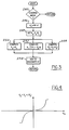
- the quadratic speed control term is calculated by multiplying quadratic constant k q times the product of error signal v e and the absolute value of error signal v e . This particular multiplication is used to advantage for generating a quadratic control term having the sign of error signal v e .
- the quadratic, integral, and proportional control terms are then added in step 258 to generate throttle position command signal TP. As described later herein with particular reference to Figure 5, throttle position command signal TP causes stepper motor 50 to turn to the commanded throttle position.
- is plotted as a function of speed error signal v e . It is noted that at low speed error signals (such as v e less than 1 mph), the quadratic control term is relatively small due to its squaring feature. On the other hand, the quadratic control term contributes substantially at higher speed error signals. To prevent excessive contribution at high speed error signals, the quadratic control term is clipped or limited at predetermine positive and negative limits.
- An advantage of the quadratic control term utilised herein is that small speed error signals are essentially ignored thereby providing a more stable speed control system. On the other hand, large corrections are quickly provided for significant speed errors thereby achieving a speed control system with a relatively fast response time.
- throttle position command TP is provided in a manner described later herein with particular reference to Figure 4.
- throttle position command TP is compared to total phase count ⁇ c which, as described below, infers the actual position of stepper motor 50 and accordingly the throttle plate (not shown).
- the difference between throttle position TP and phase count ⁇ c is representative of the angular position which stepper motor 50 must be incremented or decremented to in order to achieve the throttle position commanded by microcomputer 42.
- a sequence of phase pulses ( ⁇ 1, ⁇ 2, and ⁇ 3) is generated during step 276 for turning stepper motor 50 to throttle position TP.
- phase pulses ⁇ 1, ⁇ 2, and ⁇ 3 are generated for turning stepper motor 50 in discrete phase steps, each pulse is counted to provide a total phase count ⁇ c in step 278 which is related to the actual position of stepper motor 50.
- the above described process then continues the next background loop of microcomputer 42 when a new throttle position command is received.
- step 282 Upon recognition of the SET COMMAND in step 282, a rounded off value of actual vehicle speed at the time of actuation of SET/ACCEL switch 36 is stored as a set or desired speed in the rs memory location (see step 284). Stepper motor 50 is then zeroed or turned to an idle position and electromagnetic clutch assembly 56 engaged during steps 288 and 290.
- the integrator memory is initialised with initial throttle position TP i in step 294 a SET COMMAND (as described in greater detail later herein, a similar initialising process occurs after a RESUME COMMAND or ACCEL COMMAND).
- Stepper motor 50 is then advanced until its angular position, as represented by phase count ⁇ c , reaches initial throttle position TP i as shown by process steps 298 and 300.
- Actual vehicle speed existing at that time is then stored as initial reference speed ms i during process step 304.
- reference speed ms is incremented in a preprogrammed manner until desired speed rs is achieved.
- speed error signal v e is generated by subtracting actual vehicle speed (v) from reference speed ms as reference speed ms is being incremented (step 308).
- Proportional gain constant k p , quadratic gain constant k q , and integral gain constant k I are set in a manner described later herein with particular reference to Figures 15 and 16.
- throttle position (TP) is determined in the same manner as previously described herein with particular reference to process steps 250, 252, 254, and 258 shown in Figure 3.
- the programming for incrementing reference speed ms is provided in steps 322-334. In general, a preselected number of ramps are utilised dependent upon vehicle speed. If vehicle speed is less than initial reference speed ms i plus predetermined deviation ⁇ 1 (such as one mile per hour), then initial reference speed ms i is incremented at predetermined Rate 1.
- reference speed ms is incremented at predetermined Rate 2.
- reference speed ms is set equal to desired speed rs during step 330.
- ms is incremented at Rate 3 from ms i to rs for providing gradual vehicle acceleration to reference speed rs.
- the control mode is entered as indicated by process step 336 in Figure 6.
- speed control system 10 maintains vehicle speed at reference speed rs.
- speed control system 10 is initialised with an adaptively learned target throttle position such that desired speed rs is achieved in a stable manner with minimal undershoot, overshoot, or abrupt changes in vehicle speed.
- the adaptive learning process of target throttle positioning enables speed control system 10 to automatically adapt to different vehicles, and to variations among the same vehicle upon which it may be installed.
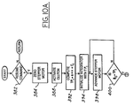
- step 382 stepper motor 50 is turned to an idle position (see step 384) and electromagnetic clutch assembly 56 activated (see step 388).
- initial throttle position TP i is computed by multiplying vehicle speed existing at the time resume switch 38 is depressed times slope value "a" and adding adaptively learned offset value c i .
- the integrator memory is then initialised with the computed initial target position TP i (see step 394).
- Stepper motor 50 is advanced until it reaches a phase count associated with target throttle position TP i (see steps 398 and 400).
- Actual vehicle speed v is then stored as reference speed ms i in step 404.
- step 408 speed error signal v e is computed by subtracting vehicle speed from reference speed ms.
- Proportional gain constant k p , quadratic gain constant k q , and integral gain constant k I are set in step 410.
- throttle position TP is determined in the same manner as previously described herein with particular reference to process steps 250, 252, 254, and 258 shown in Figure 3.
- FIG. 10A-10B Figures 11A-11C, and Figures 12A-12C.
- Figures 11A-11D represent a hypothetical resume operation wherein reference speed ms is greater than actual vehicle speed v (i.e., v e > zero) throughout resume operations.
- Figures 12A-12C represent a more complex hypothetical resume operation wherein actual vehicle speed v exceeds reference speed ms (i.e., v e ⁇ zero) during a portion of resume operation.
- Resume speed control operation is first described of conditions when vehicle speed v is less than reference speed ms (i.e., v e > zero). After a determination is made that the speed error signal v e is positive (see step 430) and reference speed ms is less than set speed rs (see step 432), vehicle speed v is compared to various speed ranges (see steps 434, 436, and 438). More specifically, when vehicle speed v is less than predetermined value 3 from set speed rs and within predetermined value ⁇ 1 from initial reference speed ms i , reference speed ms is incremented at predetermined rate R1 as shown by steps 434, 436, and 438.
- reference speed ms is incremented at rate R2 (see step 440). If vehicle speed v is greater than set speed rs minus ⁇ 3 (see step 434), reference speed ms is incremented at rate R3 (see step 442) until reference speed ms reaches set speed rs (see steps 432 and 446).
- reference speed ms is initialised with vehicle speed v when stepper motor 50 reaches target throttle position TP i at time t2.
- Initial reference speed ms i is then gradually advanced at rate R1 until vehicle speed v reaches initial reference speed ms i plus ⁇ 1 at time t3.
- reference speed ms is incremented at rate R2 until vehicle speed v reaches set speed rs minus 3 at time t4.
- reference speed ms is incremented at rate R3 until it reaches set speed rs at time t5.
- this integrator resetting operation reduces throttle position thereby reducing or eliminating any speed overshoot.
- Speed control operation when speed error signal v e is negative (i.e., v > ms) during a portion of resume operation is now described with continuing reference to Figures 10A-10B, and reference to the hypothetical example graphically shown in Figures 12A-12C.
- Vehicle speed is first compared to an upper reference speed ums (see step 460) which, in this particular example, is generated by adding a predetermined value m to reference speed ms during each background loop of microcomputer 42.
- reference speed ms is incremented to upper reference speed ums as shown in steps 460 and 462.
- reference speed ms is updated with vehicle speed v (step 468).
- reference speed ms is incremented at rate R3 when vehiclHspeed is within a predetermined range ⁇ 3 of set speed rs.
- Resume switch 38 is shown actuated at time t1 in Figure 12A.
- stepper motor 50 is turned to target throttle position TP i .
- line 470 represents reference speed ms incremented at rates R1, R2, and R3 under hypothetical conditions where vehicle speed v is less than reference speed ms.
- line 472 represents upper reference speed ums which is incremented at rates R1, R2, and R3 under hypothetical conditions where vehicle speed v is less than upper reference speed ums.
- Line 474 represents actual vehicle speed v for the example presented herein.
- the solid portions of lines 470, 472, and 474 represent the actual reference speed ms utilised for speed error control in the particular example presented herein.
- reference speed ms is increased at rate R1 until it is greater than initial reference speed ms i plus ⁇ 1 as shown at time t3. Thereafter, reference speed ms is increased at rate R2. As shown in the previous example presented herein with reference to Figures 11A-11C, reference speed ms would increase at rate R2 until vehicle speed v reaches set speed rs minus ⁇ 3. However, as shown in the particular example presented in Figure 12B, vehicle speed v exceeds reference speed ms at time t4. Reference speed ms is therefore set to vehicle speed v at time t4.
- smooth resume operation is provided which adapts to actual vehicle speed under conditions of operator acceleration and downhill operation.
- unique manner of initialising the integrator with throttle position based upon vehicle speed v and reinitialising the integrator with target throttle position based upon set speed rs provides smooth and stable operation with minimal undershoot or overshoot.
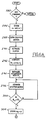
- gain values k p , and k I are adjusted during the control mode as a function of speed error v e .
- speed control response is reduced at small speed errors and enhanced at large speed errors such that quadratic control component k q *v e *
- the gain control operation described herein is an alternate embodiment to the quadratic control previously described herein.
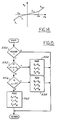
- step 490 absolute speed error v e is compared to preselected error ⁇ e in step 492.
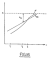
- the functional relationship is linear as shown in Figure 14.
- variable gain operation is now described when the absolute value of speed error v e is greater than the preselected error e (step 492).
- Figure 14 shows a first linear relationship (labelled as f1) between gain k p and speed error v e until speed error v e reaches predetermined speed error e . At such time, the linear relationship between gain k p and speed error v e is increased (labelled as d1).
- f1 first linear relationship between gain k p and speed error v e until speed error v e reaches predetermined speed error e .
- d1 the linear relationship between gain k p and speed error v e is increased
- the gain amplitude of the speed control system is substantially increased such that speed undershoot (such as when encountering a hill) or speed overshoot (such as when cresting a hill) are thereby avoided.
- the gain relationship at positive or negative speed errors is also alterable to compensate for variations in vehicle response to positive or negative speed errors.
- the gain operation described herein presents an alternative to a particular aspect of the Resume Mode of operation previously described with reference to Figures 10A-10B, 11A-11C, and 12A-12C.
- desired speed ms was incremented at a plurality of preselected rates to asymptotically converge upon reference speed rs.
- a single rate is utilised and the gain values (k p , k I , and k q ) are varied to achieve an asymptotic approach.
- Other aspects of resume operation however, such as initialising and reinitialising the integrator, storage location remain substantially the same.
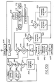
- vehicle speed v is checked to whether it is within predetermined range ⁇ k of resume or reference speed rs during step 552.
- gain constants k p1 , k I1 , and k q1 are read from memory for respective gain values k p , k I , and k q as shown in step 554.
- These gain values are greater than the gain values which will be described below such that more rapid convergence of speed control operation towards reference speed rs is provided after initiation of the Resume Mode of operation. Accordingly, an advantage is obtained of minimising any droop in vehicle speed which may otherwise occur upon initiation of the Resume Mode or other speed alteration modes of operation.
- step 552 when vehicle speed v is within range ⁇ k of reference speed rs (step 552), and speed error v e is positive (i.e., vehicle speed v is less than desired speed ms as determined in step 556) gain values k p2 , k I2 , and k q2 are read from memory during step 558.
- the gain constants subscripted with 2 are less than those gain constants subscripted with 1. Accordingly, when the vehicle speed is within range ⁇ k from reference speed rs, vehicle speed converges more gradually towards the reference speed.
- gain constants k p3 , k I3 , and k q3 are read from memory during step 562.
- the gain constants subscripted with 3 are less than the gain constants subscripted with 1. Accordingly, when resume or reference speed rs is being approached and vehicle speed v is overshooting desired speed ms (such as when travelling on a down grade) relatively small gain constants are utilised for convergence upon reference speed rs with minimal or substantially no overshoot.
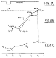
- resume operation commences at time t 1 .
- resume operation such as initialising the integrator with a best guess throttle position turning stepper motor 50 to the best guess position and reinitialising the integrator upon reaching reference speed rs are not repeated herein.
- vehicle speed v is less than range ⁇ k from reference speed rs. Accordingly, gain constants subscript with 1 such as k p1 are utilised by speed control system 10. During the interval between times t2 and t3, vehicle speed v is within range ⁇ k and also less than desired speed ms. Accordingly, gain constants subscripted with 2 such as k p2 are utilised to more gradually converge upon reference speed rs.
- vehicle speed v is shown greater than ms (i.e., speed error v e is negative) so that gain constants subscripted with 3 are utilised.
- ms i.e., speed error v e is negative
- gain constants subscripted with 3 will slow down the convergence towards reference speed rs thereby minimising or eliminating any speed overshoot.
- rapid convergence is provided at the initiation of a speed alteration such as during initiation of the Resume Mode.
- convergence is slowed and slowed further when any indication of overshoot is provided.
Claims (7)
- Geschwindigkeitsregelsystem (10), das die Motordrossel regelt, um die FahrzeugGeschwindigkeit auf einer gewünschten Geschwindigkeit zu halten, das die folgenden Bestandteile enthält;
Unterscheidungsmittel (246) zur Erzeugung eines Fehlersignals mit einer Amplitude, die sich auf einen Vergleich zwischen der Fahrzeuggeschwindigkeit und der gewünschten Geschwindigkeit bezieht;
Korrekturmittel (250, 252, 254) zur Erzeugung eines Korrektursignals, das sich auf das genannte Fehlersignal bezieht und das genannte Korrektursignal mit einem einstellbaren Verstärkungswert multipliziert;
und Betätigungsmittel (272, 274, 276, 278) zur Betätigung der Motordrossel in Bezug zum Korrektursignal, das mit dem einstellbaren Verstärkungswert multipliziert wurde;
dadurch gekennzeichnet, daß das System ferner in sich einschließt;
Verstärkungseinstellmittel (492, 494, 498, 514, 518) zur Schaffung des variablen Verstärkungswertes mit einer variablen Amplitude, die als eine lineare Funktion des genannten Fehlersignals erzeugt wird, wobei die genannte variable Amplitude eine erste lineare Funktion des genannten Fehlersignals ist, wenn das genannte Fehlersignal kleiner als eine vorgegebene Amplitude ist, und eine zweite lineare Funktion des genannten Fehlersignals ist, wenn das genannte Fehlersignal die vorgegebene Amplitude übersteigt, wobei die genannte zweite lineare Funktion sich von der ersten linearen Funktion unterscheidet. - System nach Anspruch 1, bei welchem das Korrekturmittel (250, 252, 254) eine Vielzahl von Korrektusignalen schafft, von denen sich jedes auf das genannte Fehlersignal bezieht und jedes der genannten Signale mit einem jeweiligen einer gleichen Vielzahl von entsprechenden einstellbaren Verstärkungswerten multipliziert; wobei die Verstärkungseinstellmittel (492, 494, 498, 514, 518) für jeden der entsprechenden einstellbaren Verstärkungswerte eine variable Amplitude vorsieht, die als eine erste lineare Funktion des genannten Fehlersignals erzeugt wird, wenn das genannte Fehlersignal kleiner als die vorgegebene Amplitude ist und eine zweite lineare Funktion, wenn das genannte Fehlersignal die vorgebene Amplitude übersteigt; wobei ein Summiermittel (258) vorgesehen ist, um ein Regelsignal durch die Summierung des Produktes aus jedem der Korrektursignale multipliziert mit seinem jeweiligen einstellbaren Verstärkungswert zu erzeugen.
- System nach Anspruch 2, bei welchem das genannte Korrekturmittel ein erstes Korrektursignal durch Multiplizierung des genannten Fehlersignals mit einem ersten jeweiligen einstellbaren Verstärkungswert liefert.
- System nach Anspruch 3, bei welchem das genannte Korrekturmittel ein zweites Korrektursignal durch Integration des genannten Fehlersignals und durch Multiplizierung des genannten integrierten Fehlersignals mit einem zweiten jeweiligen einstellbaren Verstärkungswert liefert.
- System nach Anspruch 1, 2, 3 oder 4, bei welchem die zweite lineare Funktion eine größere Empfindlichkeit auf das Fehlersignal schafft als die erste lineare Funktion.
- Geschwindigkeitsregelverfahren zur Regelung der Motordrossel, um die FahrzeugGeschwindigkeit auf einer gewünschten Geschwindigkeit zu halten, welches die folgenden Schritte in sich einschließt;
Vergleich (246) der Fahrzeuggeschwindigkeit mit der gewünschten Geschwindigkeit, um ein Fehlersignal zu erzeugen;
Erzeugung (250, 252, 254) eines auf das genannte Fehlersignal bezogenen Korrektursignals und Multiplizierung des genannten Korrektursignals mit einem einstellbaren Verstärkungswert;
und Betätigung der Motordrossel (272, 274, 276, 278) in Bezug zur Multiplizierung des Korrektursignals mit dem einstellbaren Verstärkungswert;
dadurch gekennzeichnet, daß das Verfahren ferner umfaßt;
die Vorsehung (492, 494, 498, 514, 518) des einstellbaren Verstärkungswerts mit einer variablen Amplitude, die als eine lineare Funktion des genannten Fehlersignals erzeugt wird, wobei die genannte variable Amplitude eine erste lineare Funktion des genannten Fehlersignals ist, wenn das genannte Fehlersignal kleiner als eine vorgegebene Amplitude ist und eine zweite lineare Funktion wenn das genannte Fehlersignal die genannte vorgegebene Amplitude überschreitet, wobei sich die genannte zweite lineare Funktion von der genannten ersten linearen Funktion unterscheidet. - System nach Anspruch 6, bei welchem der genannte die Verstärkung erzeugende Schritt bei der genannten zweiten linearen Funktion eine größere Empfindlichkeit für das genannte Fehlersignal vorsieht als bei der genannten ersten linearen Funktion.
Applications Claiming Priority (3)
| Application Number | Priority Date | Filing Date | Title |
|---|---|---|---|
| US74346191A | 1991-08-09 | 1991-08-09 | |
| US743461 | 1991-08-09 | ||
| PCT/EP1992/001720 WO1993002885A1 (en) | 1991-08-09 | 1992-07-29 | Speed control system with variable gains related to speed error |
Publications (2)
| Publication Number | Publication Date |
|---|---|
| EP0597922A1 EP0597922A1 (de) | 1994-05-25 |
| EP0597922B1 true EP0597922B1 (de) | 1996-01-31 |
Family
ID=24988861
Family Applications (1)
| Application Number | Title | Priority Date | Filing Date |
|---|---|---|---|
| EP92916214A Expired - Lifetime EP0597922B1 (de) | 1991-08-09 | 1992-07-29 | System zur Geschwindigkeitsregelung mit variabler Verstärkung in Abhängigkeit der Geschwindigkeitsabweichung |
Country Status (6)
| Country | Link |
|---|---|
| US (1) | US5329455A (de) |
| EP (1) | EP0597922B1 (de) |
| JP (1) | JPH07501291A (de) |
| CA (1) | CA2114955A1 (de) |
| DE (1) | DE69208092T2 (de) |
| WO (1) | WO1993002885A1 (de) |
Cited By (1)
| Publication number | Priority date | Publication date | Assignee | Title |
|---|---|---|---|---|
| DE19604220B4 (de) * | 1996-02-06 | 2013-02-07 | Robert Bosch Gmbh | Verfahren und Vorrichtung zur Regelung bzw. Begrenzung der Fahrgeschwindigkeit eines Fahrzeugs |
Families Citing this family (17)
| Publication number | Priority date | Publication date | Assignee | Title |
|---|---|---|---|---|
| DE4128627C2 (de) * | 1991-08-26 | 1994-06-23 | Mannesmann Ag | Verfahren zur Veränderung der Geschwindigkeit eines Fahrzeuges und Fahrzeug zur Durchführung dieses Verfahrens |
| US6026784A (en) | 1998-03-30 | 2000-02-22 | Detroit Diesel Corporation | Method and system for engine control to provide driver reward of increased allowable speed |
| US5417193A (en) * | 1994-01-25 | 1995-05-23 | Textron Inc. | Engine speed control system and method |
| US5429089A (en) * | 1994-04-12 | 1995-07-04 | United Technologies Corporation | Automatic engine speed hold control system |
| US5949675A (en) * | 1996-11-01 | 1999-09-07 | Space Systems/Loral, Inc. | Transient-free gain switching within error threshold |
| DE19858294C2 (de) | 1998-12-17 | 2000-11-02 | Daimler Chrysler Ag | Verfahren zur Fahrgeschwindigkeitsregelung eines Kraftfahrzeuges |
| US6157888A (en) * | 1999-02-08 | 2000-12-05 | Ford Global Technologies, Inc. | Input smoothing method and apparatus for an electronic throttle control system |
| US6196189B1 (en) * | 1999-06-18 | 2001-03-06 | Caterpillar Inc. | Method and apparatus for controlling the speed of an engine |
| US6196188B1 (en) | 1999-07-15 | 2001-03-06 | Cummins Engine Co Inc | System and method for maintaining a constant throttle deadband |
| US6289873B1 (en) * | 2000-05-02 | 2001-09-18 | General Electric Company | System and method for controlling an engine during a bog condition |
| US7233854B2 (en) * | 2004-09-13 | 2007-06-19 | General Motors Corporation | Method for improving fuel economy and performance when deactivating cylinders with vehicle cruise control |
| US7894971B2 (en) * | 2005-12-28 | 2011-02-22 | Toyota Jidosha Kabushiki Kaisha | Vehicle control apparatus |
| JP4314250B2 (ja) * | 2006-05-23 | 2009-08-12 | トヨタ自動車株式会社 | 車両用の路面判定装置 |
| US7536992B1 (en) * | 2008-03-27 | 2009-05-26 | International Engine Intellectual Property Company, Llc | Engine speed controller having PI gains set by engine speed and engine speed error |
| US9085237B2 (en) * | 2011-10-03 | 2015-07-21 | Fuji Jukogyo Kabushiki Kaisha | Speed limiter |
| JP5602186B2 (ja) * | 2012-05-28 | 2014-10-08 | マイクロスペース株式会社 | モータ駆動制御装置 |
| US10272778B2 (en) * | 2017-01-18 | 2019-04-30 | Baidu Usa Llc | Method and system for determining unit gain of speed control for autonomous driving vehicles |
Family Cites Families (12)
| Publication number | Priority date | Publication date | Assignee | Title |
|---|---|---|---|---|
| US3885644A (en) * | 1973-12-10 | 1975-05-27 | Philco Ford Corp | Variable gain vehicle speed control system |
| DE2537415C2 (de) * | 1975-08-22 | 1982-05-19 | Robert Bosch Gmbh, 7000 Stuttgart | Regelkreis zum Regeln der Fahrgeschwindigkeit eines Kraftfahrzeuges |
| US4098242A (en) * | 1976-06-17 | 1978-07-04 | Barber-Colman Company | Automatic control system with gain switching |
| JPS59136533A (ja) * | 1983-01-27 | 1984-08-06 | Honda Motor Co Ltd | オートクルーズ制御装置 |
| JPH0739252B2 (ja) * | 1985-10-09 | 1995-05-01 | 日本電装株式会社 | 車両速度制御装置 |
| EP0227198B1 (de) * | 1985-12-26 | 1991-03-27 | Fujitsu Ten, Ltd. | System zur Geschwindigkeitsregelung durch Einstellung der Solleistung und ein Verfahren zur Regulierung mit Phasenvoreilung |
| US4803637A (en) * | 1986-07-17 | 1989-02-07 | Toyota Jidosha Kabushiki Kaisha | Cruise control system for a vehicle |
| US4856609A (en) * | 1986-07-18 | 1989-08-15 | Mitsubishi Denki Kabushiki Kaisha | Constant-speed running control device for vehicles |
| JPH0686187B2 (ja) * | 1987-01-28 | 1994-11-02 | トヨタ自動車株式会社 | 定速走行制御装置 |
| JPH01154666A (ja) * | 1987-12-11 | 1989-06-16 | Nitsuko Corp | Posシステム |
| JPH01269617A (ja) * | 1988-04-20 | 1989-10-27 | Toyota Motor Corp | 車両用定速走行制御装置 |
| JPH03217337A (ja) * | 1990-01-20 | 1991-09-25 | Mitsubishi Electric Corp | 車両用定速走行装置 |
-
1992
- 1992-07-29 EP EP92916214A patent/EP0597922B1/de not_active Expired - Lifetime
- 1992-07-29 DE DE69208092T patent/DE69208092T2/de not_active Expired - Fee Related
- 1992-07-29 WO PCT/EP1992/001720 patent/WO1993002885A1/en active IP Right Grant
- 1992-07-29 JP JP5503252A patent/JPH07501291A/ja active Pending
- 1992-07-29 CA CA002114955A patent/CA2114955A1/en not_active Abandoned
-
1993
- 1993-09-03 US US08/116,821 patent/US5329455A/en not_active Expired - Fee Related
Cited By (1)
| Publication number | Priority date | Publication date | Assignee | Title |
|---|---|---|---|---|
| DE19604220B4 (de) * | 1996-02-06 | 2013-02-07 | Robert Bosch Gmbh | Verfahren und Vorrichtung zur Regelung bzw. Begrenzung der Fahrgeschwindigkeit eines Fahrzeugs |
Also Published As
| Publication number | Publication date |
|---|---|
| DE69208092D1 (de) | 1996-03-14 |
| EP0597922A1 (de) | 1994-05-25 |
| JPH07501291A (ja) | 1995-02-09 |
| CA2114955A1 (en) | 1993-02-18 |
| WO1993002885A1 (en) | 1993-02-18 |
| US5329455A (en) | 1994-07-12 |
| DE69208092T2 (de) | 1996-06-05 |
Similar Documents
| Publication | Publication Date | Title |
|---|---|---|
| EP0597922B1 (de) | System zur Geschwindigkeitsregelung mit variabler Verstärkung in Abhängigkeit der Geschwindigkeitsabweichung | |
| EP0425276B1 (de) | Laufzustand-Steuerungssystem für ein Kraftfahrzeug | |
| US5420793A (en) | Vehicle speed control system with quadratic feedback control | |
| US5177683A (en) | Speed control system with adaptive resume mode | |
| EP0051002B1 (de) | Automatische Geschwindigkeitssteueranlage für schwere Fahrzeuge | |
| EP0597944B1 (de) | Geschwindigkeitsregelung für fahrzeug mit adaptivem lernen | |
| US5495251A (en) | Method of and apparatus for cruise control | |
| EP0051000B1 (de) | Automatische Geschwindigkeitssteueranlage für schwere Fahrzeuge | |
| US4169437A (en) | Speed control system for a vehicle | |
| JP3358509B2 (ja) | 車両用走行制御装置 | |
| US5634446A (en) | Cruise control based retarder control | |
| EP0051004B1 (de) | Automatische Geschwindigkeitssteueranlage für schwere Fahrzeuge | |
| JPS599740B2 (ja) | 自動車の走行速度の調整装置 | |
| US5260876A (en) | Speed control system with adaptive gain control during a speed alteration | |
| US4870584A (en) | System and method for automatically running a vehicle at a desired cruising speed | |
| US4597465A (en) | Cruise control system and method with overspeed sensor | |
| US5177682A (en) | Speed control system with resume mode override | |
| EP0600481B1 (de) | Elektronisches Regelsystem mit Verzögerungsrückführung für ein Bremssystem | |
| US5477457A (en) | Cruise control system for motorcars | |
| EP0519477B1 (de) | Vorrichtung zur Aufrechterhaltung einer gleichbleibenden Geschwindigkeit eines Kraftfahrzeuges | |
| US5390119A (en) | Vehicle speed control system with resume/cancel function | |
| GB2350699A (en) | Setting the controlled speed of a vehicle | |
| GB1588860A (en) | Skid control system | |
| US4905154A (en) | Method for compensating for cable length in a vehicle electronic speed control system | |
| US5064014A (en) | Method of controlling power steering system |
Legal Events
| Date | Code | Title | Description |
|---|---|---|---|
| PUAI | Public reference made under article 153(3) epc to a published international application that has entered the european phase |
Free format text: ORIGINAL CODE: 0009012 |
|
| 17P | Request for examination filed |
Effective date: 19940211 |
|
| AK | Designated contracting states |
Kind code of ref document: A1 Designated state(s): DE FR GB |
|
| 17Q | First examination report despatched |
Effective date: 19940905 |
|
| GRAA | (expected) grant |
Free format text: ORIGINAL CODE: 0009210 |
|
| AK | Designated contracting states |
Kind code of ref document: B1 Designated state(s): DE FR GB |
|
| REF | Corresponds to: |
Ref document number: 69208092 Country of ref document: DE Date of ref document: 19960314 |
|
| ET | Fr: translation filed | ||
| PLBE | No opposition filed within time limit |
Free format text: ORIGINAL CODE: 0009261 |
|
| STAA | Information on the status of an ep patent application or granted ep patent |
Free format text: STATUS: NO OPPOSITION FILED WITHIN TIME LIMIT |
|
| 26N | No opposition filed | ||
| REG | Reference to a national code |
Ref country code: FR Ref legal event code: TP Ref country code: FR Ref legal event code: CD |
|
| REG | Reference to a national code |
Ref country code: GB Ref legal event code: IF02 |
|
| PGFP | Annual fee paid to national office [announced via postgrant information from national office to epo] |
Ref country code: GB Payment date: 20030704 Year of fee payment: 12 |
|
| PGFP | Annual fee paid to national office [announced via postgrant information from national office to epo] |
Ref country code: DE Payment date: 20030710 Year of fee payment: 12 |
|
| PGFP | Annual fee paid to national office [announced via postgrant information from national office to epo] |
Ref country code: FR Payment date: 20030711 Year of fee payment: 12 |
|
| PG25 | Lapsed in a contracting state [announced via postgrant information from national office to epo] |
Ref country code: GB Free format text: LAPSE BECAUSE OF NON-PAYMENT OF DUE FEES Effective date: 20040729 |
|
| PG25 | Lapsed in a contracting state [announced via postgrant information from national office to epo] |
Ref country code: DE Free format text: LAPSE BECAUSE OF NON-PAYMENT OF DUE FEES Effective date: 20050201 |
|
| GBPC | Gb: european patent ceased through non-payment of renewal fee |
Effective date: 20040729 |
|
| PG25 | Lapsed in a contracting state [announced via postgrant information from national office to epo] |
Ref country code: FR Free format text: LAPSE BECAUSE OF NON-PAYMENT OF DUE FEES Effective date: 20050331 |
|
| REG | Reference to a national code |
Ref country code: FR Ref legal event code: ST |