EP0597921B1 - Machines electriques polyphasees a couches d'enroulement prefabriquees - Google Patents
Machines electriques polyphasees a couches d'enroulement prefabriquees Download PDFInfo
- Publication number
- EP0597921B1 EP0597921B1 EP92916182A EP92916182A EP0597921B1 EP 0597921 B1 EP0597921 B1 EP 0597921B1 EP 92916182 A EP92916182 A EP 92916182A EP 92916182 A EP92916182 A EP 92916182A EP 0597921 B1 EP0597921 B1 EP 0597921B1
- Authority
- EP
- European Patent Office
- Prior art keywords
- winding
- conductor
- electric machine
- soft magnetic
- winding layers
- Prior art date
- Legal status (The legal status is an assumption and is not a legal conclusion. Google has not performed a legal analysis and makes no representation as to the accuracy of the status listed.)
- Expired - Lifetime
Links
Images


Classifications
-
- H—ELECTRICITY
- H02—GENERATION; CONVERSION OR DISTRIBUTION OF ELECTRIC POWER
- H02K—DYNAMO-ELECTRIC MACHINES
- H02K3/00—Details of windings
- H02K3/04—Windings characterised by the conductor shape, form or construction, e.g. with bar conductors
- H02K3/12—Windings characterised by the conductor shape, form or construction, e.g. with bar conductors arranged in slots
-
- H—ELECTRICITY
- H02—GENERATION; CONVERSION OR DISTRIBUTION OF ELECTRIC POWER
- H02K—DYNAMO-ELECTRIC MACHINES
- H02K21/00—Synchronous motors having permanent magnets; Synchronous generators having permanent magnets
- H02K21/12—Synchronous motors having permanent magnets; Synchronous generators having permanent magnets with stationary armatures and rotating magnets
- H02K21/24—Synchronous motors having permanent magnets; Synchronous generators having permanent magnets with stationary armatures and rotating magnets with magnets axially facing the armatures, e.g. hub-type cycle dynamos
-
- H—ELECTRICITY
- H02—GENERATION; CONVERSION OR DISTRIBUTION OF ELECTRIC POWER
- H02K—DYNAMO-ELECTRIC MACHINES
- H02K3/00—Details of windings
- H02K3/46—Fastening of windings on the stator or rotor structure
- H02K3/50—Fastening of winding heads, equalising connectors, or connections thereto
-
- H—ELECTRICITY
- H02—GENERATION; CONVERSION OR DISTRIBUTION OF ELECTRIC POWER
- H02K—DYNAMO-ELECTRIC MACHINES
- H02K7/00—Arrangements for handling mechanical energy structurally associated with dynamo-electric machines, e.g. structural association with mechanical driving motors or auxiliary dynamo-electric machines
- H02K7/10—Structural association with clutches, brakes, gears, pulleys or mechanical starters
- H02K7/102—Structural association with clutches, brakes, gears, pulleys or mechanical starters with friction brakes
-
- H—ELECTRICITY
- H02—GENERATION; CONVERSION OR DISTRIBUTION OF ELECTRIC POWER
- H02K—DYNAMO-ELECTRIC MACHINES
- H02K7/00—Arrangements for handling mechanical energy structurally associated with dynamo-electric machines, e.g. structural association with mechanical driving motors or auxiliary dynamo-electric machines
- H02K7/14—Structural association with mechanical loads, e.g. with hand-held machine tools or fans
-
- Y—GENERAL TAGGING OF NEW TECHNOLOGICAL DEVELOPMENTS; GENERAL TAGGING OF CROSS-SECTIONAL TECHNOLOGIES SPANNING OVER SEVERAL SECTIONS OF THE IPC; TECHNICAL SUBJECTS COVERED BY FORMER USPC CROSS-REFERENCE ART COLLECTIONS [XRACs] AND DIGESTS
- Y10—TECHNICAL SUBJECTS COVERED BY FORMER USPC
- Y10T—TECHNICAL SUBJECTS COVERED BY FORMER US CLASSIFICATION
- Y10T29/00—Metal working
- Y10T29/49—Method of mechanical manufacture
- Y10T29/49002—Electrical device making
- Y10T29/49009—Dynamoelectric machine
- Y10T29/49012—Rotor
Definitions
- the invention relates to a multi-phase electrical machine according to the preamble of claim 1.
- the invention is therefore based on the object of developing a multi-phase electrical machine, the rotors and stands of which lie opposite one another in a flat surface and which has at least one grooved soft-magnetic body for receiving prefabricated winding layers, in such a way that even in several phases a high space utilization in reached the slots and end windings and the length of the conductor strands can be kept small regardless of the slot depth.
- the complete winding consists of a package of identical winding layers, which are stacked on top of each other in the direction of the slot depth.
- Each winding layer is made up of prefabricated conductor strands of different phases.
- the conductor strands are verbally divided into partial areas, partial areas lying within the soft magnetic body as slot bars, partial areas lying in the winding head, which run in the direction of the slots, as slot bar connecting pieces, and also partial areas lying in the winding head, but which run in the direction of the slot width as Webs are called.
- a conductor strand or the series connection of a few phase conductor strands of winding layers lying on top of one another constitute a circuit of the electrical machine.
- the height of a conductor strand is reduced to approximately half the conductor height in the grooves during or shortly after every second transition of the conductor strand from the soft magnetic body into a winding head.
- webs of conductor strands from the same winding layer are arranged, but which belong to different phases.
- the webs of conductor strands of a winding layer are arranged one behind the other in the winding heads in the direction of the slots.
- the reduction in the conductor height is largely compensated for in the slot rod connector by widening the conductor cross section by one tooth width in the direction of the slot width.
- Sub-sections of the conductor strand that do not overlap with other conductor strands of the same layer in the winding end can take up the full layer height and thus have conductor cross-sections that are approximately twice as large as the sub-sections in the slots.
- conductor strands of different phases are arranged at the same distance from the slot opening plane, the number of these conductor strands, which together form a self-supporting winding layer, corresponding to the number of phases of the machine.
- the overlap problem in the winding overhangs is solved by changes in the conductor cross-section, the conductor height of the overlapping conductor strands of a layer being reduced so that the sum of their conductor heights together corresponds to the conductor height in the other subregions of the conductor strand or the layer.
- the winding layer thus has a constant height over its entire surface lying parallel to the slot opening plane, as a result of which no voids are formed when several layers are stacked on top of one another to form a larger winding.
- connection paths in the end windings are kept very short, since the webs are as close as possible to the soft magnetic body and are independent of the slot depth.
- the number of conductor strands connected in series or the number of winding layers can be increased as desired with the groove depth, the length of the individual conductor strands remaining constant. Since, in advantageous embodiments, all conductor strands of one phase are identical, the manufacturing effort remains low.
- the width of the conductor strand increases by the tooth width at each transition from the soft magnetic body into a winding overhang, as a result of which conductor strands of adjacent slots lie flat against one another in the direction of the slot width - only separated by a thin insulating layer.
- the space for current conduction in the winding head is used, which guides the magnetic flux in the direction of the groove depth in the soft magnetic body as a tooth, and the conductor cross section in the slot bar connecting pieces is increased or the reduction in the conductor height is compensated.
- the conductor strands have a short length in the end windings, since they are led away in the direction of the slot width from the respective slot bar or slot bar connector. Only conductor strands of different phases, which are also in the slots at the same distance from the slot opening plane and therefore together form a winding layer, influence each other in the space distribution in the winding head. While the conductor length and the manufacturing effort are almost independent of the groove depth, the losses and costs associated with the yoke and magnet volume decrease with increasing groove depth.
- the embodiment in which the distances of the webs from the soft magnetic body in the two winding heads are the same in each conductor strand is referred to in the description as a winding with symmetrical winding heads . It is also characterized by the fact that one-piece conductor strands are assembled into a winding layer in their prefabricated form and, if no adhesive is used, the compact winding layer can also be broken down into the individual conductor strands at any time.
- the one-piece production of a conductor strand guarantees that the conductor strand has the lowest internal resistance corresponding to its cross sections and lengths. This is a prerequisite for achieving low levels of efficiency and high power and power densities.
- the design as a disc rotor represents a large area of application of the invention. Because of the high force density that can be achieved, a permanently excited disc rotor is particularly suitable as a direct drive for installation in the wheel rim of a vehicle.
- the rotor can be axially displaceably connected to the rim base, as a result of which stress on the rotor due to bending, for example due to axial forces occurring when cornering, is avoided.
- the heat sink upstream of the winding heads and inferences can be designed as supporting elements of the rim and the rotor disk as part of a braking device. This significantly reduces the risk of breakage for the powerful magnets, and the entire rim structure is less rigid and easier to carry out.
- winding layers are replaced by flat cooling elements through which a coolant flows, without this resulting in an increase in the yoke, magnet and conductor volume.
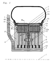
- FIG. 1 shows the structure of a disc rotor installed in a wheel rim, with prefabricated winding layers.
- the wheel rim is denoted by 1 and the tire picked up by the rim flange la by 2.
- the disk rotor itself consists of the rotor disk 3 , in which permanent magnets 3a are installed, and the two stator halves 4 and 5 .
- the stator halves 4 and 5 are supported with respect to the rim 1 and the rim bed 1b by bearings 6 , and each consist of a soft magnetic body 4a , 5a , of which only the inference 4b , 5b is visible in FIG. 1, and the windings 4c and 5c , which are designed differently to illustrate the invention.
- a winding 4c with asymmetrical winding heads is shown on the left of the rotor disk 3 and a winding 5c with two-layer winding layers and symmetrical winding heads is shown on the right.
- the rotor disk 3 is connected to the rim base 1b by a toothed drive in such a way that the rim 1 can move axially under axial load in order to avoid stressing the rotor due to bending.
- the rim base can be designed, for example, as a cage with axially extending grooves, which engage the teeth of the rotor disk. The axial extent of the teeth is less than that of the grooves.
- the inferences 4b , 5b of the soft magnetic bodies and the windings 4c and 5c are embedded in the heat sink 8 , which essentially functions as a carrier of the rim base 1b , and is connected to the hub 9 .
- the hub is designed as a hollow shaft to reduce weight, and the power electronics could also be accommodated in the cavity up to the axis of rotation 7 .
- the current leads for the individual winding layers are located in the heat sink, the current being supplied to the winding layers through commutation devices, consisting of a current distribution plate 10 and power transistors 11 .
- a disc brake device 12 is also provided in the heat sink itself, the brake shoes 12a of the disc brake device acting on the rotor disk 3 .
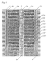
- FIG. 2 shows a section along the line II-II from FIG. 1.
- a winding with four slots per pole pitch is shown.
- the slot bars forming a winding layer are designated with 13a - 13d , the slots of the adjacent pole pitch with 13a ' - 13d' . 2 that the rotor between the magnetic segments 3a has pole gaps 3b .
- FIG. 3a shows a view along the line III-III from FIG. 1.
- the slot rods sitting in the grooves are again designated 13a - 13d and connected to the slot rods 13a ' - 13d' by slot rod connecting pieces 15a-15d or 15a'-15d ' and webs 14a-14d ; the web 14a is not visible since it lies behind the slot bar connectors 15a-15c .
- Such a unit as shown in FIG. 3a in the top view of the upper layer half, forms a winding layer 4d and the complete winding is created by the axial layering of several of these winding layers one behind the other.
- FIG. 3b shows the same winding layer 4d as in FIG. 3a, but in a section through the lower half of the layer.
- the web 14a is visible here and the slot rod connecting pieces 15a-15d lying above it are not.
- the hatching of the lower half of the layer is rotated by 90 ° compared to the hatching for the upper half of the layer.
- FIG. 4a shows a conductor strand of the winding layer from FIG. 3, again showing a winding with asymmetrical winding heads in a four-phase disc rotor with three pole pairs.
- the two end windings are each indicated by four auxiliary lines 19 which represent the limits of the four web areas.
- the conductor strand is characterized by two hatching patterns, the hatching lines running from the bottom left to the top right, the upper layer 20 and the hatching lines running from the top left to the bottom symbolizing the bottom layer 21 .
- the type of hatching shows in which areas the conductor strand occupies the full layer height and in which places the lower or the upper half of the layer has gaps.
- a conductor strand comprises the entire machine circumference minus one pole pitch. At this gap, either the current supply line 17 and current derivation 18 for actuation take place or, if several conductor strands are connected in series in the machine, the transition to a conductor strand adjacent in the direction of the groove depth takes place.
- the winding head space between the connections 17 and 18 is used by supply and discharge connections of other conductor strands.
- variable conductor cross-section in the winding overhangs, it is of course also possible to implement alternative conductor strand profiles in which the arrangements of the overlaps or constrictions differ from the previously described exemplary embodiment.
- FIG. 4b a conductor strand of a winding layer consisting of a winding with symmetrical winding heads in a four-phase disk armature with three pole pairs is shown in FIG. 4b .
- the web 16b in the outer winding head is at the same distance from the soft magnetic body as the webs in the inner winding head 16b ' or 14c.
- the hatching lines have the same meaning as in Fig. 4a.
- FIG. 5 shows sections from the three conductor strands of a three-phase winding layer with asymmetrical winding heads. Only one section of each conductor strand is shown, which corresponds to two pole pitches. All conductor strands fictitiously begin in the middle of their slot in the first pole pitch and end in the middle of the slot in the third pole pitch.
- the sections shown in one piece belong to conductor strands made of an annular winding layer for a disc rotor and therefore have curved webs with different lengths.
- the lower conductor strand 22 also has on the left side in the area of webs 25 recesses in the upper layer half and on the right side in the area of the extended Nutstabanschluß Swisse recesses 30 in the upper layer half on.
- the cutouts in the webs 25 and 31 and the slot bar connection pieces 26 and 30 complement each other in such a way that the two strands can lie in one layer.
- the recesses in the conductor strands 22 and 23 also allow the insertion of the conductor strand 24 , the slot rod connector 28 , which is reduced in the conductor height, running in the recesses of the webs 25 and 27 and the web 33, likewise reduced in cross section, over the slot rod connectors 30 and 32 .
- the conductor strands in FIG. 6 have grooved rod connectors and webs of the same design in both winding heads. Again, a simple pushing together of the conductor strands in the direction of the groove depth is possible by inserting the slot bar connectors 38a, 38b of the conductor strand 35 , which are reduced in their conductor height , into the recesses in the webs 37a, 37b of conductor strand 34 .
- the recesses of the slot bar connectors 40a and 40b of the conductor strand 36 fit exactly into the space formed by the projections in the webs 37a and 39a or 37b and 39b .
- all three sections can form a winding layer with a constant height.
- each conductor strand regardless of its length and its position in a winding layer, consists of only two different segment designs 41 and 42 , which in turn consist of four different stamped parts 41a and 41b or 42a and 42b were joined together.
- the four segments 41 and 42 shown in a row running from the bottom left to the top right are inserted in this order into a corresponding shape and then heated to such an extent under pressure that they fuse to form a one-piece conductor strand.
- Another embodiment of the invention is represented by two-layer winding layers, which enable a uniform and 100% utilization of the winding head space.
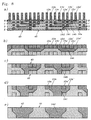
- FIG. 8 a shows a section of the conductor course in a two-layer winding layer for a four-phase linear motor, the section comprising four pole pitches in a symmetrical winding head.
- the conductor profiles of the upper layer 45 are hatched more densely and, as in FIG. 3, in slot bars 13a.13d , slot bar connecting pieces 15a-15d and webs 14a . 14b divided and marked by hatching lines that run from bottom left to top right.
- the hatching lines of the conductor courses of the lower layer 46 are rotated by 90 °, that is, they run from the top left to the bottom right.
- FIG. 8a furthermore shows where the cuts BB, CC , D-D and E-E lie, which are shown in FIGS. 8b, 8c, 8d and 8e.
- These sectional drawings represent the real side view of all the web layers in a winding head of the two-layer, four-phase winding layer.
- the types of hatching correspond to the hatching used in FIG. 8a.
- the conductor height of the webs partially corresponds to twice the conductor height of the slots, particularly in the outer end winding areas, but the two layers remain identical.
Abstract
Claims (10)
- Machine électrique polyphasée à couches d'enroulement préfabriquées, laquelle possède au moins un corps magnétique doux avec des rainures de cale et dont le rotor (1, 3) et le stator (4, 5) font face sur une surface égale, la plaine de la fente d'air, lesdites couches d'enroulement se trouvant parallèle à la plaine de la fente d'air,
caractérisée en ce qu'une couche d'enroulement (4d) se compose au moins de deux cordes conductrices (22 - 24 au 34 -36) de phases différentes, lesquelles montrent des variations de la section du conducteur (25 - 33 au 37a - 40b) des deux côtés en dehors du corps magnétique doux (4a). - Machine électrique polyphasée à couches d'enroulement préfabriquées selon la revendication 1,
caractérisée en ce que la section du conducteur d'une corde conductrice (22 au 34) d'une couche d'enroulement (4d), ladite corde conductrice possédant dans des zones partielles (25, 30 au 37a, 37b) arrangées en dehors du corps magnétique doux (4a) une section plus petite en direction de la profondeur de la rainure que dans les sections se trouvant à l'intérieur du corps magnétique doux (4a). - Machine électrique polyphasée à couches d'enroulement préfabriquées selon la revendication 2,
caractérisée en ce que la section du conducteur d'une corde conductrice (23 au 35) d'une couche d'enroulement (4d), ladite corde conductrice possédant dans des zones partielles (26, 32 au 38a, 38b), lesquelles se dirigent en direction de la rainure, mais qui se trouvent en même temps en dehors du corps magnétique doux (4a) et lesquelles ont des sections réduites en direction de la profondeur de la rainure, la réduction desdites sections du conducteur créant un espace dans lequel se trouvent des liens (25, 33 au 37a, 37b) des autres cordes conductrices (22, 24 au 34) de la même couche d'enroulement. - Machine électrique polyphasée à couches d'enroulement préfabriquées selon la revendication 1,
caractérisée en ce que la section du conducteur d'une corde conductrice (23, 24 au 36) d'une couche d'enroulement, ladite corde conductrice possédant dans des zones partielles (26, 28, 32 au 40a, 40b), lesquelles se dirigent en direction de la rainure, mais qui se trouvent en même temps en dehors du corps magnétique doux (4a), et lesquelles sont plus grandes en direction de la largeur de la rainure en comparaison avec les zones partielles (13a - d) à l'intérieur du corps magnétique doux (4a). - Machine électrique polyphasée à couches d'enroulement préfabriquées selon la revendication 1, dans laquelle les cordes conductices des couches d'enroulement différentes se trouvent l'une sur l'autre en direction de la profondeur de la rainure,
caractérisée en ce qu'une couche d'enroulement dans laquelle des zones partielles (25, 27 au 37a, 39a) des cordes conductices (22, 23 au 34, 35) se dirigent en direction de la largeur de la rainure, lesdites zones partielles des cordes conductrices de phases différentes se trouvent l'une derrière l'autre en direction de la rainure, mais aussi ayent la même distance envers la plaine de la fente d'air. - Machine électrique polyphasée à couches d'enroulement préfabriquées selon la revendication 1,
caractérisée en ce que la somme des longueurs des deux bouts des barres de la rainure (15c' et 15") lesquelles sont liés à une barre de la rainure, cette somme étant pareille pour toutes cordes conductices (22, 23, 24) d'une couche d'enroulement (4d). - Machine électrique polyphasée à couches d'enroulement préfabriquées selon la revendication 1,
caractérisée en ce qu'une couche d'enroulement (4d) dans laquelle des zones partielles (37a,37b au 39a, 39b) des cordes conductrices (34, 35)se dirigent en direction de la largeur de la rainure, lesdites zones partielles ont la même distance du corps magnétique doux (4a) en les deux têtes d'enroulement. - Machine électrique polyphasée à couches d'enroulement préfabriquées selon l'une des revendications précédentes,
caractérisée en ce que les cordes conductrices (45, 46) se trouvent l'une sur l'autre en direction de la profondeur de la rainure et lesquelles sont déplacées par une division du pôle, la hauteur du conducteur en direction de la profondeur de la rainure correspond en des parties des liéns (14b - d) à la double hauteur du conducteur des barres de la rainure (13a - d). - Machine électrique polyphasée à couches d'enroulement préfabriquées selon l'une des revendications précédentes, ladite machine électrique étant une armature disque permanentement excitée,
caractérisée en ce que l'armature disque permanentement excitée à l'intérieur de la roue sert d'entraînement directe, le disque du rotor (3) étant lié à la jante (1) par un pignon qui transmet sans jeu la force dans la jante. - Machine électrique polyphasée à couches d'enroulement préfabriquées selon l'une des revendications précédentes,
caractérisée en ce qu'un élément plat pour refroidir dans lequel coule un moyen de refroidir, est situé entre deux couches d'enroulement (4d).
Applications Claiming Priority (3)
| Application Number | Priority Date | Filing Date | Title |
|---|---|---|---|
| DE4125044 | 1991-07-29 | ||
| DE4125044A DE4125044A1 (de) | 1991-07-29 | 1991-07-29 | Als scheibenlaeufer ausgebildeter elektromotor mit radial zur rotationsachse angeordnetem rotor und blechpaket |
| PCT/DE1992/000617 WO1993003534A1 (fr) | 1991-07-29 | 1992-07-29 | Machines electriques polyphasees a couches d'enroulement prefabriquees |
Publications (2)
| Publication Number | Publication Date |
|---|---|
| EP0597921A1 EP0597921A1 (fr) | 1994-05-25 |
| EP0597921B1 true EP0597921B1 (fr) | 1996-01-03 |
Family
ID=6437215
Family Applications (1)
| Application Number | Title | Priority Date | Filing Date |
|---|---|---|---|
| EP92916182A Expired - Lifetime EP0597921B1 (fr) | 1991-07-29 | 1992-07-29 | Machines electriques polyphasees a couches d'enroulement prefabriquees |
Country Status (7)
| Country | Link |
|---|---|
| US (1) | US5616977A (fr) |
| EP (1) | EP0597921B1 (fr) |
| JP (1) | JP2704915B2 (fr) |
| AU (1) | AU2348692A (fr) |
| CA (1) | CA2114219C (fr) |
| DE (1) | DE4125044A1 (fr) |
| WO (1) | WO1993003534A1 (fr) |
Families Citing this family (45)
| Publication number | Priority date | Publication date | Assignee | Title |
|---|---|---|---|---|
| KR900003245B1 (ko) * | 1986-05-14 | 1990-05-12 | 삼성전자 주식회사 | 비디오 테이프 레코오더의 구동장치 |
| DE4234145C1 (de) * | 1992-10-09 | 1994-02-03 | Wolfgang Hill | Mehrphasige elektrische Maschinem mit vorgefertigten Leitersträngen und Verfahren zu ihrer Herstellung |
| EP0669051B1 (fr) * | 1992-10-09 | 1998-08-05 | HILL, Wolfgang | Machine electrique polyphasee comportant des tiges pour encoches coaxiales |
| DE59400954D1 (de) * | 1993-04-30 | 1996-12-05 | Robert Prof Dr Ing Massen | Verfahren und vorrichtung zur sortierung von materialteilen |
| DE4321236C1 (de) * | 1993-06-25 | 1994-08-25 | Wolfgang Hill | Mehrphasige elektrische Maschine mit einer Wicklung aus flachen Leiterformteilen |
| DE4339409A1 (de) * | 1993-11-18 | 1995-05-24 | Union Sils Van De Loo & Co | Nabenlichtmaschine mit Scheibenbremse |
| DE4411750C2 (de) * | 1994-04-06 | 1997-06-05 | Wolfgang Hill | Dreiphasige elektrische Maschine mit verflochtenen Leiterschichten |
| US5804902A (en) * | 1994-04-06 | 1998-09-08 | Hill; Wolfgang | Multi-phase electric machine with joined conductor lanes |
| US5942830A (en) * | 1994-04-06 | 1999-08-24 | Hill; Wolfgang | Three-phase electric machine with interlaced conductor layers |
| DE4427323C2 (de) * | 1994-08-02 | 2001-06-07 | Wolfgang Hill | Elektrische Maschine mit Permanentmagneten und Erregerfeldwicklungen |
| DE19501926A1 (de) * | 1995-01-23 | 1996-07-25 | Egon Schmid | Antriebseinrichtung für ein elektrisch betriebenes Fahrzeug |
| DE19524542C2 (de) * | 1995-07-05 | 1997-07-24 | Wolfgang Hill | Mehrphasige elektrische Maschine und Verfahren zu ihrer Herstellung |
| DE19632390C2 (de) * | 1996-08-01 | 2000-03-16 | Wolfgang Hill | Mehrphasige elektrische Maschine mit einer raumoptimierten Schichtwicklung |
| DE19706585B4 (de) * | 1997-02-21 | 2004-04-29 | Weigl, Jörg Dieter | Scheibenbremsen-Dynamo |
| FR2765041B1 (fr) * | 1997-06-20 | 2004-04-16 | Jeumont Ind | Procede de bobinage et bobines pour machine electrique tournante |
| US6281614B1 (en) * | 1997-08-01 | 2001-08-28 | Wolfgang Hill | Multiple phase electric machine with a space-optimized turn-to-turn winding |
| US6348751B1 (en) * | 1997-12-12 | 2002-02-19 | New Generation Motors Corporation | Electric motor with active hysteresis-based control of winding currents and/or having an efficient stator winding arrangement and/or adjustable air gap |
| JP2001320845A (ja) * | 2000-05-10 | 2001-11-16 | Mitsubishi Electric Corp | 回転電機の固定子 |
| US6882077B2 (en) * | 2002-12-19 | 2005-04-19 | Visteon Global Technologies, Inc. | Stator winding having cascaded end loops |
| US6787961B2 (en) | 2002-12-19 | 2004-09-07 | Visteon Global Technologies, Inc. | Automotive alternator stator assembly with varying end loop height between layers |
| US6935011B2 (en) * | 2002-08-05 | 2005-08-30 | Visteon Global Technologies, Inc. | Method of forming a stator for a brushless motor |
| DE602004013722D1 (de) * | 2003-02-07 | 2008-06-26 | Core Motion Inc | Optimierte leiteranordnung für eine axialfeld-drehenergieeinrichtung |
| US6965183B2 (en) * | 2003-05-27 | 2005-11-15 | Pratt & Whitney Canada Corp. | Architecture for electric machine |
| US7583063B2 (en) | 2003-05-27 | 2009-09-01 | Pratt & Whitney Canada Corp. | Architecture for electric machine |
| US6768239B1 (en) | 2003-06-23 | 2004-07-27 | Magnetic Power-Motion, Llc | Electromotive devices using notched ribbon windings |
| US7948139B2 (en) * | 2006-05-19 | 2011-05-24 | Pratt & Whitney Canada Corp. | Magnetic control circuit separation slit |
| GB0613570D0 (en) | 2006-07-07 | 2006-08-16 | Imp Innovations Ltd | An electrical machine |
| AU2008234418B2 (en) * | 2007-04-03 | 2012-02-02 | Launchpoint Electric Propulsion Solutions, Inc. | Winding arrangement for an electrical machine |
| DE102012212693A1 (de) * | 2011-07-21 | 2013-01-24 | Honda Motor Co., Ltd. | Stator für eine elektrische Rotationsmaschine und Herstellungsverfahren desselben |
| JP5389109B2 (ja) * | 2011-07-21 | 2014-01-15 | 本田技研工業株式会社 | 回転電機のステータ |
| KR101552982B1 (ko) * | 2012-07-12 | 2015-09-14 | 현대모비스 주식회사 | 인휠 구동장치 |
| FR3015794B1 (fr) * | 2013-12-20 | 2017-07-14 | Save Ingenierie | Element de machine electromagnetique a circuits electromagnetiques optimises integres a des pistes sous forme de lignes crenelees annulaires |
| RU2568186C2 (ru) * | 2014-03-12 | 2015-11-10 | Федеральное государственное бюджетное образовательное учреждение высшего профессионального образования "Самарский государственный технический университет" | Экономичная двухслойная обмотка электрической машины |
| CN105071573B (zh) * | 2015-07-16 | 2017-05-31 | 擎声自动化科技(上海)有限公司 | 一种具有印刷电路板绕组的定子结构 |
| US11139707B2 (en) | 2015-08-11 | 2021-10-05 | Genesis Robotics And Motion Technologies Canada, Ulc | Axial gap electric machine with permanent magnets arranged between posts |
| AU2016304787B2 (en) | 2015-08-11 | 2021-01-07 | Genesis Robotics And Motion Technologies Canada, Ulc | Electric machine |
| US9673684B2 (en) * | 2015-10-02 | 2017-06-06 | E-Circuit Motors, Inc. | Structures and methods for thermal management in printed circuit board stators |
| US11527933B2 (en) | 2015-10-02 | 2022-12-13 | E-Circuit Motors, Inc. | Stator and rotor design for periodic torque requirements |
| US11043885B2 (en) | 2016-07-15 | 2021-06-22 | Genesis Robotics And Motion Technologies Canada, Ulc | Rotary actuator |
| US11005322B2 (en) | 2017-06-05 | 2021-05-11 | E-Circuit Motors, Inc. | Rotor assemblies for axial flux machines |
| US11831211B2 (en) | 2017-06-05 | 2023-11-28 | E-Circuit Motors, Inc. | Stator and rotor design for periodic torque requirements |
| DE102019112100A1 (de) * | 2019-05-09 | 2020-11-12 | Deutsches Zentrum für Luft- und Raumfahrt e.V. | Elektrische Baueinheit mit einer Wicklung und Verfahren zu ihrer Herstellung |
| KR20230155466A (ko) | 2021-02-17 | 2023-11-10 | 이-서킷 모터스 인코퍼레이티드 | 축방향 플럭스 기계를 위한 평면형 고정자 구성 |
| CA3227417A1 (fr) * | 2021-07-30 | 2023-02-02 | E-Circuit Motors, Inc. | Cartes de circuit imprime remplies de materiau magnetique et stators de carte de circuit imprime |
| US11336130B1 (en) * | 2021-08-17 | 2022-05-17 | E-Circuit Motors, Inc. | Low-loss planar winding configurations for an axial flux machine |
Family Cites Families (18)
| Publication number | Priority date | Publication date | Assignee | Title |
|---|---|---|---|---|
| DE558486C (de) * | 1928-12-22 | 1932-09-07 | Siemens Schuckertwerke Akt Ges | Stabwicklung fuer elektrische Kommutatormaschinen |
| US2469808A (en) * | 1946-09-28 | 1949-05-10 | Gen Mills Inc | Induction motor rotor |
| US2683232A (en) * | 1949-09-21 | 1954-07-06 | Siemens Ag | Winding assembly for disk-type electric motors or generators |
| DE1123758B (de) * | 1959-02-05 | 1962-02-15 | S E A Soc D Electronique Et D | Rotierende elektrische Maschine mit scheibenfoermigen Rotor- und Statorelementen |
| FR1405924A (fr) * | 1964-06-01 | 1965-07-16 | Comp Generale Electricite | Perfectionnements apportés aux machines électriques |
| DE1267321B (de) * | 1965-01-21 | 1968-05-02 | Lloyd Dynamowerke G M B H | Elektrische Doppelmaschine in Scheibenbauweise |
| GB1247344A (en) * | 1967-12-05 | 1971-09-22 | Nat Res Dev | Dynamo-electric machines |
| CH503415A (fr) * | 1968-12-20 | 1971-02-15 | Merlin Gerin | Moteur à induction linéaire |
| GB1323062A (en) * | 1969-07-16 | 1973-07-11 | Parsons Co Ltd C A | Dynamo-electric machines |
| NL163075C (nl) * | 1976-07-12 | 1980-07-15 | Gils Adrianus Van | Gelamineerde wikkeling voor elektrische machines. |
| DE2835386A1 (de) * | 1978-08-12 | 1980-02-21 | Kabel Metallwerke Ghh | Verfahren zur herstellung der wicklung fuer einen linearmotor |
| CH662990A5 (en) * | 1983-11-30 | 1987-11-13 | Delta Ag | Electric independent wheel drive |
| US4543503A (en) * | 1983-12-20 | 1985-09-24 | General Electric Company | Ventilated end turns for rotor windings of a dynamoelectric machine |
| US5093598A (en) * | 1989-07-28 | 1992-03-03 | Westinghouse Electric Corp. | Semiconductor insulation layer for stator coil connections |
| EP0414927A1 (fr) * | 1989-08-28 | 1991-03-06 | Siemens Aktiengesellschaft | Enroulement statorique refroidi par liquide pour une machine d'entraînement électrique |
| US5252880A (en) * | 1992-11-24 | 1993-10-12 | General Electric Company | Dynamoelectric machine rotor endwindings with cooling passages |
| JPH06209535A (ja) * | 1993-01-07 | 1994-07-26 | Toyota Motor Corp | モータのコイル構造 |
| US5332939A (en) * | 1993-01-15 | 1994-07-26 | General Electric Company | Electrical stator |
-
1991
- 1991-07-29 DE DE4125044A patent/DE4125044A1/de active Granted
-
1992
- 1992-07-29 AU AU23486/92A patent/AU2348692A/en not_active Abandoned
- 1992-07-29 WO PCT/DE1992/000617 patent/WO1993003534A1/fr active IP Right Grant
- 1992-07-29 CA CA002114219A patent/CA2114219C/fr not_active Expired - Fee Related
- 1992-07-29 JP JP5503176A patent/JP2704915B2/ja not_active Expired - Lifetime
- 1992-07-29 US US08/190,026 patent/US5616977A/en not_active Expired - Lifetime
- 1992-07-29 EP EP92916182A patent/EP0597921B1/fr not_active Expired - Lifetime
Also Published As
| Publication number | Publication date |
|---|---|
| JPH06506822A (ja) | 1994-07-28 |
| CA2114219C (fr) | 2002-04-30 |
| AU2348692A (en) | 1993-03-02 |
| JP2704915B2 (ja) | 1998-01-26 |
| DE4125044C2 (fr) | 1993-09-16 |
| EP0597921A1 (fr) | 1994-05-25 |
| DE4125044A1 (de) | 1993-02-04 |
| US5616977A (en) | 1997-04-01 |
| WO1993003534A1 (fr) | 1993-02-18 |
| CA2114219A1 (fr) | 1993-02-18 |
Similar Documents
| Publication | Publication Date | Title |
|---|---|---|
| EP0597921B1 (fr) | Machines electriques polyphasees a couches d'enroulement prefabriquees | |
| EP1114500B1 (fr) | Moteur electrique | |
| DE60311045T2 (de) | Segmentierter Anker und AC-Maschine, die selbigen benutzt | |
| EP3637590A2 (fr) | Bobine électrique fabriquée par la technique de coulée | |
| DE19818432A1 (de) | Gleichstrommotor | |
| EP0705494A1 (fr) | Machine electrique a phases multiples avec un enroulement constitue de conducteurs faconnes plats | |
| WO2019215097A1 (fr) | Procédé de fabrication d'un enroulement pour un stator d'une machine électrique et machine électrique | |
| WO2015007456A2 (fr) | Ensemble bobine, ensemble stator, machine électrique et procédé de fabrication d'un stator | |
| DE19704769C2 (de) | Mehrsträngige Synchronmaschine mit Permanentmagneten und Spulenmodulen | |
| DE4008446C2 (fr) | ||
| EP2523313A2 (fr) | Machine électrique à enroulement ondulé avec branches parallèles | |
| DE4234175C2 (de) | Mehrphasige elektrische Maschine mit schleifenlos montierten Leitersträngen | |
| EP3813237B1 (fr) | Module de bobine pour une machine électrique | |
| EP3167540B1 (fr) | Procédé de fabrication d'une machine électrique comportant des bobines formées et machine électrique et outil de fabrication | |
| DE4302807C2 (de) | Mehrphasige elektrische Maschine und Verfahren zu ihrer Herstellung | |
| EP0682825B1 (fr) | Machine electrique polyphasee a unites multipolaires decalees | |
| WO2021110198A1 (fr) | Machine à flux axial comprenant un stator ayant des segments de tôle s'étendant radialement | |
| EP0916177B1 (fr) | Machine electrique polyphasee a enroulements en nappes a espace optimise | |
| DE4234129A1 (de) | Mehrphasige elektrische Maschine mit zusammenmontierbaren Leiterlagen | |
| DE2717058C2 (de) | Spule für Pole einer elektrischen Maschine | |
| EP3958438A1 (fr) | Moteur électrique pourvu de stator optimisé | |
| EP4203256A1 (fr) | Stator pour une machine électrique, machine électrique et véhicule | |
| WO2024018055A1 (fr) | Stator pour machine électrique | |
| EP4320708A1 (fr) | Stator de machine électrique à flux axial et machine à flux axial | |
| WO2022243018A1 (fr) | Ensemble bobine |
Legal Events
| Date | Code | Title | Description |
|---|---|---|---|
| PUAI | Public reference made under article 153(3) epc to a published international application that has entered the european phase |
Free format text: ORIGINAL CODE: 0009012 |
|
| 17P | Request for examination filed |
Effective date: 19940223 |
|
| AK | Designated contracting states |
Kind code of ref document: A1 Designated state(s): CH FR GB IT LI |
|
| 17Q | First examination report despatched |
Effective date: 19941013 |
|
| GRAA | (expected) grant |
Free format text: ORIGINAL CODE: 0009210 |
|
| AK | Designated contracting states |
Kind code of ref document: B1 Designated state(s): CH FR GB IT LI |
|
| ITF | It: translation for a ep patent filed |
Owner name: DR. ING. AUSSERER ANTON |
|
| ET | Fr: translation filed | ||
| GBT | Gb: translation of ep patent filed (gb section 77(6)(a)/1977) |
Effective date: 19960418 |
|
| PG25 | Lapsed in a contracting state [announced via postgrant information from national office to epo] |
Ref country code: LI Effective date: 19960731 Ref country code: CH Effective date: 19960731 |
|
| PLBE | No opposition filed within time limit |
Free format text: ORIGINAL CODE: 0009261 |
|
| STAA | Information on the status of an ep patent application or granted ep patent |
Free format text: STATUS: NO OPPOSITION FILED WITHIN TIME LIMIT |
|
| 26N | No opposition filed | ||
| REG | Reference to a national code |
Ref country code: CH Ref legal event code: PL |
|
| REG | Reference to a national code |
Ref country code: GB Ref legal event code: IF02 |
|
| REG | Reference to a national code |
Ref country code: GB Ref legal event code: 746 Effective date: 20020725 |
|
| PG25 | Lapsed in a contracting state [announced via postgrant information from national office to epo] |
Ref country code: IT Free format text: LAPSE BECAUSE OF NON-PAYMENT OF DUE FEES Effective date: 20050729 |
|
| PGFP | Annual fee paid to national office [announced via postgrant information from national office to epo] |
Ref country code: GB Payment date: 20060731 Year of fee payment: 15 |
|
| PGFP | Annual fee paid to national office [announced via postgrant information from national office to epo] |
Ref country code: FR Payment date: 20060803 Year of fee payment: 15 |
|
| GBPC | Gb: european patent ceased through non-payment of renewal fee |
Effective date: 20070729 |
|
| PG25 | Lapsed in a contracting state [announced via postgrant information from national office to epo] |
Ref country code: GB Free format text: LAPSE BECAUSE OF NON-PAYMENT OF DUE FEES Effective date: 20070729 |
|
| REG | Reference to a national code |
Ref country code: FR Ref legal event code: ST Effective date: 20080331 |
|
| PG25 | Lapsed in a contracting state [announced via postgrant information from national office to epo] |
Ref country code: FR Free format text: LAPSE BECAUSE OF NON-PAYMENT OF DUE FEES Effective date: 20070731 |