EP0596832B1 - Vertikale Plattensäge - Google Patents
Vertikale Plattensäge Download PDFInfo
- Publication number
- EP0596832B1 EP0596832B1 EP93810748A EP93810748A EP0596832B1 EP 0596832 B1 EP0596832 B1 EP 0596832B1 EP 93810748 A EP93810748 A EP 93810748A EP 93810748 A EP93810748 A EP 93810748A EP 0596832 B1 EP0596832 B1 EP 0596832B1
- Authority
- EP
- European Patent Office
- Prior art keywords
- saw
- panel
- horizontal
- supporting grid
- framework
- Prior art date
- Legal status (The legal status is an assumption and is not a legal conclusion. Google has not performed a legal analysis and makes no representation as to the accuracy of the status listed.)
- Expired - Lifetime
Links
Images
Classifications
-
- B—PERFORMING OPERATIONS; TRANSPORTING
- B23—MACHINE TOOLS; METAL-WORKING NOT OTHERWISE PROVIDED FOR
- B23Q—DETAILS, COMPONENTS, OR ACCESSORIES FOR MACHINE TOOLS, e.g. ARRANGEMENTS FOR COPYING OR CONTROLLING; MACHINE TOOLS IN GENERAL CHARACTERISED BY THE CONSTRUCTION OF PARTICULAR DETAILS OR COMPONENTS; COMBINATIONS OR ASSOCIATIONS OF METAL-WORKING MACHINES, NOT DIRECTED TO A PARTICULAR RESULT
- B23Q11/00—Accessories fitted to machine tools for keeping tools or parts of the machine in good working condition or for cooling work; Safety devices specially combined with or arranged in, or specially adapted for use in connection with, machine tools
- B23Q11/0042—Devices for removing chips
- B23Q11/0046—Devices for removing chips by sucking
Definitions
- the invention relates to a vertical panel saw according to the preamble of the independent claim.
- EP-A-0 244 358 discloses a vertical panel saw type described above, in which the end wall is anchored directly to the support grid and that of the workpiece support side facing away from the back of the support grate throughout closes so that horizontal channels are formed, through the adjacent grate strips, the end wall and limited by the placed workpiece during sawing are.
- the wood dust thrown tangentially from the saw blade passes through a horizontal channel into one at the edge of the Panel saw arranged vertical suction shaft and is there through the combined effect of gravity and suction removed down.
- this vertical panel saw has the disadvantage that that the wood dust is first horizontal in a closed Canal must be transported, which requires that Workpiece adjacent to the suction shaft on the support grate hang up or between the suction shaft and the edge of the Workpiece the workpiece support side of the support grate with a To close the sealing wall. Because the horizontal channels closed the grate strips must not be included be provided with vertical recesses so that Vertical cuts only made on the edge of the support grate can be.
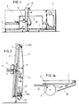
- FIG. 1 shows a vertical panel saw with a practically vertical, that is, slightly inclined frame 1 and a support grid 2, depending on the frame in a known manner the respective altitude of the in horizontal cutting position located saw unit vertically slidably mounted is to ensure that the saw blade at Horizontal section always between two adjacent support bars comes to rest.
- a slidable along the frame 1 Saw beam 3 carries the one that can be tilted by 90 ° Saw unit 4, the 5 via a suction line to a Vacuum source, not shown, is connected.
- the suction line 5 opens into a practically saw dust-tight Chamber K, which surrounds the saw blade S.
- horizontal workpiece supports 6 and 7 are also attached, on which the workpiece to be sawed also supports its lower edge.
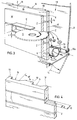
- the support grid 2 the structure of which derives from the 4 results in perspective detail a plurality of horizontal strips 8 (Fig. 3), the Spaces Z are formed as narrow slots.
- the The height b of these slots essentially corresponds to the saw blade thickness c (Fig. 3), so that the saw blade S is unimpeded and contact-free in the relevant slot Z can penetrate that but within the slot above and no significant exit gap below the saw blade S. remains for the wood dust thrown off the saw blade.
- a side wall 9 facing away between one clamped lower U-profile 10a and an upper U-profile 10b, that - as Fig. 3 shows - a slight crowning having.
- This end wall 9 extends practically over the entire back surface of the panel saw and defines a suction space 11 with the support grate 2 (Fig. 2), in the lower section of which is about the Total length of the suction space 11 extending suction pipe 12 is arranged.
- the one provided with inlet openings 13 Suction tube 12 is connected to a vacuum source, not shown.
- the horizontal distance "a" of the end wall 9 of the support grate 2 is preferably chosen so that the saw dust thrown off the rotating saw blade by the end wall either not at all, or only in insignificant dimensions is thrown back, so that the saw dust after entering the suction chamber 11 can no longer get into the support grate slots Z.
- the support grate 2 can for example consist of a homogeneous plate to be worked out on their the Workpiece W (Fig. 3) facing away from vertical grooves N has slots, while from the front of the plate Z are incorporated, which are continuous in the area of the grooves N, that is, are open after the extraction room. Connect the webs 18 left between the grooves N. the strips separated by the slots Z into one rigid unity.
- each web 18 is chamfered at an angle ⁇ (Fig. 3 and 4).
- the support grid can also one with horizontally running slots Z
- height b of the support grate slots Z serves not only to limit the backflow of wood dust, but also also contributes to the prevention of accidents, since now with certainty no one with a finger in or behind one of the Slots Z can enter.
- the interception element 20 can be used as a rigid plate or for example in Be shaped like a flexible bellows so that it if necessary up to the edge of the work in progress workpiece can be used.
Landscapes
- Engineering & Computer Science (AREA)
- Mechanical Engineering (AREA)
- Sawing (AREA)
- Securing Of Glass Panes Or The Like (AREA)
- Toilet Supplies (AREA)
- Panels For Use In Building Construction (AREA)
- Processing Of Stones Or Stones Resemblance Materials (AREA)
Description
Claims (6)
- Vertikale Plattensäge zur Anbringung von Horizontal- und Vertikalschnitten an insbesondere grossflächigen Platten aus Holz, Kunststoff und deren Verbundmaterialien, mit einem mindestens annähernd vertikalen Gestell (1), einem an diesem, auf dessen Arbeitsseite befestigten Stützrost (2) mit einer Vielzahl paralleler, in gegenseitigem gleichem Abstand vorgesehener Zwischenräume (Z) zur Aufnahme des beim Horizontalschnitt das Werkstück überragenden Sägeblattrandes, einem das um 90° kippbare, vertikal verschiebbare Sägeaggregat (4) tragenden, längs des Gestells (1) verfahrbaren Sägebalken (3), sowie mit einer sich praktisch über die gesamte Plattensäge erstreckenden Abschlusswand (9) zur Abgrenzung des hinter dem Werkstück (W) anfallenden Sägestaubs, wobei der Stützrost (2) beweglich gelagert und mit der jeweiligen Höhenlage des in Horizontalschnittposition befindlichen Sägeaggregats (4) so gekoppelt ist, dass der Horizontalschnitt unabhängig vom gewählten Mass in einem der genannten Zwischenräume (Z) erfolgt, dadurch gekennzeichnet, dass die Zwischenräume (Z) als Schlitze ausgebildet sind, deren Höhe (b) im wesentlichen der Sägeblattdicke (c) entspricht, und dass die Abschlusswand (9) mit horizontalem Abstand vom Stützrost derart auf der dem Stützrost (2) abgewandten Seite des Gestells (1) angeordnet und am Gestell befestigt ist, dass in einem zusammenhängenden Raum der beim Horizontalschnitt anfallende Sägestaub hinter dem Werkstück in den zwischen dem Stützrost (2) und der Abschlusswand (9) gebildeten, unter einem Unterdruck stehenden Absaugraum (11) gelangt und dort durch die kombinierte Wirkung von Schwerkraft und Absaugung nach unten entfernt werden kann.
- Vertikale Plattensäge nach Anspruch 1, dadurch gekennzeichnet, dass der horizontale Abstand (a) der Abschlusswand von dem Stützrost (2) so gewählt ist, dass der vom rotierenden Sägeblatt (S) abgeschleuderte Sägestaub von der Abschlusswand (9) nicht, oder nur in unwesentlichem Ausmasse, zurückprallt.
- Vertikale Plattensäge nach Anspruch 1 oder 2, dadurch gekennzeichnet, dass der Stützrost (2) als homogene Platte ausgebildet ist, deren horizontale Schlitze (Z) sich von der Plattenfrontseite bis zu einer Tiefe (d) erstrecken, die kleiner als die Gesamtdicke (D) der Platte ist, und dass, von der Plattenrückseite ausgehend, quer zu den genannten Schlitzen (Z) verlaufende Nuten (N) in gegenseitigen Abständen angebracht sind, deren Tiefe mindestens der Differenz (D-d) zwischen der Platten-Gesamtdicke (D) und der Schlitztiefe (d) entspricht, derart, dass der beim Horizontalschnitt vom Sägeblatt (S) abgeschleuderte Staub durch einen der Schlitze (Z) und die Nuten (N) der Platte in den Absaugeraum (11) gelangt.
- Vertikale Plattensäge nach Anspruch 1 oder 2, dadurch gekennzeichnet, dass der Stützrost (2) eine mit horizontal verlaufenden Schlitzen versehene Frontplatte aufweist, deren durch die Schlitze voneinander getrennte Horizontalleisten durch auf deren Rückseiten in gegenseitigen Abständen befestigte, vorzugsweise aufgeklebte, und quer zu den Horizontalleisten verlaufende Verbindungsleisten zusammen gehalten sind.
- Vertikale Plattensäge nach einem der Ansprüche 1 bis 4, dadurch gekennzeichnet, dass im unteren Bereich der genannten Absaugekammer (11) ein auf seiner Gesamtlänge mit Eintrittsöffnungen (13) versehenes, an eine Vakuumquelle angeschlossenes Absaugerohr (12) angeordnet und der unterhalb des Absaugerohrs (12) befindliche, die Absaugekammer (11) nach unten abschliessende Boden (14) zwecks Austragung des sich nach unten absetzenden Sägestaubs nach unten aufklappbar ist.
- Vertikale Plattensäge nach einem der Ansprüche 1 bis 5, dadurch gekennzeichnet, dass das Gestell (1) in seinem dem jeweiligen Auslauf des Horizontalschnitts entsprechenden Randbereich ein sich mindestens über einen Grossteil seiner Gesamthöhe erstreckendes, von der Frontfläche des Gestells schräg nach aussen ragendes Abfangelement (20) für den kurz vor Fertigstellung des Horizontalschnitts nach vorne austretenden Sägestaub aufweist.
Applications Claiming Priority (2)
| Application Number | Priority Date | Filing Date | Title |
|---|---|---|---|
| CH342192 | 1992-11-04 | ||
| CH3421/92 | 1992-11-04 |
Publications (2)
| Publication Number | Publication Date |
|---|---|
| EP0596832A1 EP0596832A1 (de) | 1994-05-11 |
| EP0596832B1 true EP0596832B1 (de) | 1998-07-08 |
Family
ID=4255628
Family Applications (1)
| Application Number | Title | Priority Date | Filing Date |
|---|---|---|---|
| EP93810748A Expired - Lifetime EP0596832B1 (de) | 1992-11-04 | 1993-10-25 | Vertikale Plattensäge |
Country Status (4)
| Country | Link |
|---|---|
| EP (1) | EP0596832B1 (de) |
| AT (1) | ATE168057T1 (de) |
| DE (1) | DE59308743D1 (de) |
| ES (1) | ES2118214T3 (de) |
Families Citing this family (8)
| Publication number | Priority date | Publication date | Assignee | Title |
|---|---|---|---|---|
| ES2142051T3 (es) * | 1995-05-12 | 2000-04-01 | Reich Spezialmaschinen Gmbh | Sierra vertical de planchas. |
| DE19758436C2 (de) * | 1996-11-20 | 2000-06-08 | Willi Frigge | Sägevorrichtung mit Vorritzer |
| DE19703078C2 (de) * | 1996-11-20 | 1999-10-28 | Frigge Willi | Vertikal arbeitende Sägevorrichtung |
| CH695933A5 (de) * | 2001-11-09 | 2006-10-31 | Jost M Ambuehl | Verfahren zum Trennen von oder zum Einschneiden von Nuten in Werkstücken aus Naturstein, Kunststein oder Keramik mit einer Schneidmaschine. |
| PT1467837E (pt) | 2002-01-22 | 2006-10-31 | Pmj Automec Usa Inc D B A Pmj | Sistema de corte de paineis |
| FR3042727B1 (fr) * | 2015-10-26 | 2017-12-22 | Girardeau | Dispositif de captation de particules pour scie a panneaux verticale |
| PL428942A1 (pl) * | 2019-02-17 | 2020-08-24 | Liwoch Mirosław Glazurnictwo Mirosław Liwoch | Stół wielofunkcyjny do mechanicznej obróbki płyt, zwłaszcza glazurniczych |
| CN118478247B (zh) * | 2024-05-11 | 2024-11-08 | 江苏华力精密机械有限公司 | 一种cnc加工中心用废料收集机构及其使用方法 |
Family Cites Families (3)
| Publication number | Priority date | Publication date | Assignee | Title |
|---|---|---|---|---|
| DD122216A1 (de) * | 1975-11-07 | 1976-09-20 | ||
| CH659425A5 (de) * | 1983-05-09 | 1987-01-30 | Striebig Ag | Vorrichtung zum anbringen horizontaler und vertikaler schnitte an plattenfoermigen objekten. |
| DE8717981U1 (de) * | 1986-04-25 | 1992-01-16 | Striebig AG, Littau | Verfahren zum Absaugen des bei vertikalen Plattensägen anfallenden Holzstaubes |
-
1993
- 1993-10-25 EP EP93810748A patent/EP0596832B1/de not_active Expired - Lifetime
- 1993-10-25 DE DE59308743T patent/DE59308743D1/de not_active Expired - Lifetime
- 1993-10-25 AT AT93810748T patent/ATE168057T1/de active
- 1993-10-25 ES ES93810748T patent/ES2118214T3/es not_active Expired - Lifetime
Also Published As
| Publication number | Publication date |
|---|---|
| EP0596832A1 (de) | 1994-05-11 |
| DE59308743D1 (de) | 1998-08-13 |
| ES2118214T3 (es) | 1998-09-16 |
| ATE168057T1 (de) | 1998-07-15 |
Similar Documents
| Publication | Publication Date | Title |
|---|---|---|
| DE4205965C1 (en) | Protective hood for circular saw or combined circular cross-cut saw - has guide walls forming flow channels, which extend over top end of splitting wedge above table | |
| EP0244358B1 (de) | Verfahren zum Absaugen des bei vertikalen Plattensägen anfallenden Holzstaubes | |
| CH659425A5 (de) | Vorrichtung zum anbringen horizontaler und vertikaler schnitte an plattenfoermigen objekten. | |
| DE19520982B4 (de) | Trommelhackanlage | |
| EP1059377B1 (de) | Absaugvorrichtung an einer Textilmaschine wie insbesondere an einer Wasservernadelungseinrichtung | |
| CH620633A5 (de) | ||
| DE102007023664A1 (de) | Plattenaufteilanlage | |
| EP0824388B1 (de) | Vertikale plattensäge | |
| EP0596832A1 (de) | Vertikale Plattensäge | |
| DE3340579C2 (de) | ||
| EP0451111A1 (de) | Rationeller Plattenzuschnitt an vertikalen Plattensägen | |
| DE19519870C1 (de) | Vertikale Plattensäge | |
| EP0385983B1 (de) | Vorrichtung zur nassreinigung von rauchgas | |
| EP1310340B1 (de) | Schneidmaschine | |
| DE19838925C1 (de) | Absaugvorrichtung für horizontal betreibbare Sägemaschinen, insbesondere Plattenaufteilsägen | |
| DE19782108B4 (de) | Verfahren zum Entfernen von Staub in der Schneidepartie einer Zellstofftrockenmaschine und Vorrichtung zur Durchführung des Verfahrens | |
| DE3235201C2 (de) | ||
| DE2347256B1 (de) | Abdeckhaube fuer Kreissaegeblaetter | |
| EP0561742B1 (de) | Plattensäge mit Absaugekanal | |
| DE3506342A1 (de) | Werkzeugsupport zum drehen von werkstuecken aus holz | |
| DE102024000626A1 (de) | Vorrichtung zum Aussortieren von Abfallstücken an Sägen, vorzugsweise an Optimierungskappsägen | |
| DE2233729C3 (de) | Vorrichtung zum Auftrennen einer Matte in Abschnitte bei der Herstellung von Spanplatten, Faserplatten u. dgl | |
| AT398172B (de) | Zerkleinerungsvorrichtung | |
| DE602004006826T2 (de) | Vorrichtung zur Verarbeitung von plattenförmigen Abfällen insbesondere von Gipsplatten | |
| DE20309650U1 (de) | Zerkleinerungsmaschine |
Legal Events
| Date | Code | Title | Description |
|---|---|---|---|
| PUAI | Public reference made under article 153(3) epc to a published international application that has entered the european phase |
Free format text: ORIGINAL CODE: 0009012 |
|
| AK | Designated contracting states |
Kind code of ref document: A1 Designated state(s): AT CH DE ES FR GB IT LI NL |
|
| 17P | Request for examination filed |
Effective date: 19940630 |
|
| 17Q | First examination report despatched |
Effective date: 19961028 |
|
| GRAG | Despatch of communication of intention to grant |
Free format text: ORIGINAL CODE: EPIDOS AGRA |
|
| GRAG | Despatch of communication of intention to grant |
Free format text: ORIGINAL CODE: EPIDOS AGRA |
|
| GRAH | Despatch of communication of intention to grant a patent |
Free format text: ORIGINAL CODE: EPIDOS IGRA |
|
| GRAH | Despatch of communication of intention to grant a patent |
Free format text: ORIGINAL CODE: EPIDOS IGRA |
|
| GRAA | (expected) grant |
Free format text: ORIGINAL CODE: 0009210 |
|
| ITF | It: translation for a ep patent filed | ||
| AK | Designated contracting states |
Kind code of ref document: B1 Designated state(s): AT CH DE ES FR GB IT LI NL |
|
| REF | Corresponds to: |
Ref document number: 168057 Country of ref document: AT Date of ref document: 19980715 Kind code of ref document: T |
|
| REG | Reference to a national code |
Ref country code: CH Ref legal event code: NV Representative=s name: A. BRAUN, BRAUN, HERITIER, ESCHMANN AG PATENTANWAE Ref country code: CH Ref legal event code: EP |
|
| GBT | Gb: translation of ep patent filed (gb section 77(6)(a)/1977) |
Effective date: 19980710 |
|
| REF | Corresponds to: |
Ref document number: 59308743 Country of ref document: DE Date of ref document: 19980813 |
|
| REG | Reference to a national code |
Ref country code: ES Ref legal event code: FG2A Ref document number: 2118214 Country of ref document: ES Kind code of ref document: T3 |
|
| ET | Fr: translation filed | ||
| PLBE | No opposition filed within time limit |
Free format text: ORIGINAL CODE: 0009261 |
|
| STAA | Information on the status of an ep patent application or granted ep patent |
Free format text: STATUS: NO OPPOSITION FILED WITHIN TIME LIMIT |
|
| 26N | No opposition filed | ||
| REG | Reference to a national code |
Ref country code: GB Ref legal event code: IF02 |
|
| REG | Reference to a national code |
Ref country code: CH Ref legal event code: PFA Owner name: STRIEBIG AG Free format text: STRIEBIG AG#GROSSMATTE 26A#CH-6014 LITTAU (CH) -TRANSFER TO- STRIEBIG AG#GROSSMATTE 26A#CH-6014 LITTAU (CH) |
|
| PGFP | Annual fee paid to national office [announced via postgrant information from national office to epo] |
Ref country code: DE Payment date: 20121024 Year of fee payment: 20 Ref country code: FR Payment date: 20121128 Year of fee payment: 20 Ref country code: CH Payment date: 20121030 Year of fee payment: 20 |
|
| PGFP | Annual fee paid to national office [announced via postgrant information from national office to epo] |
Ref country code: IT Payment date: 20121019 Year of fee payment: 20 Ref country code: GB Payment date: 20121024 Year of fee payment: 20 Ref country code: ES Payment date: 20121017 Year of fee payment: 20 |
|
| PGFP | Annual fee paid to national office [announced via postgrant information from national office to epo] |
Ref country code: NL Payment date: 20121010 Year of fee payment: 20 Ref country code: AT Payment date: 20121011 Year of fee payment: 20 |
|
| REG | Reference to a national code |
Ref country code: DE Ref legal event code: R071 Ref document number: 59308743 Country of ref document: DE |
|
| REG | Reference to a national code |
Ref country code: CH Ref legal event code: PL |
|
| REG | Reference to a national code |
Ref country code: NL Ref legal event code: V4 Effective date: 20131025 |
|
| REG | Reference to a national code |
Ref country code: GB Ref legal event code: PE20 Expiry date: 20131024 |
|
| REG | Reference to a national code |
Ref country code: AT Ref legal event code: MK07 Ref document number: 168057 Country of ref document: AT Kind code of ref document: T Effective date: 20131025 |
|
| REG | Reference to a national code |
Ref country code: ES Ref legal event code: FD2A Effective date: 20140115 |
|
| PG25 | Lapsed in a contracting state [announced via postgrant information from national office to epo] |
Ref country code: DE Free format text: LAPSE BECAUSE OF EXPIRATION OF PROTECTION Effective date: 20131026 Ref country code: GB Free format text: LAPSE BECAUSE OF EXPIRATION OF PROTECTION Effective date: 20131024 |
|
| PG25 | Lapsed in a contracting state [announced via postgrant information from national office to epo] |
Ref country code: ES Free format text: LAPSE BECAUSE OF EXPIRATION OF PROTECTION Effective date: 20131026 |