EP0595905B1 - Verpackungsvorrichtung - Google Patents
Verpackungsvorrichtung Download PDFInfo
- Publication number
- EP0595905B1 EP0595905B1 EP92915712A EP92915712A EP0595905B1 EP 0595905 B1 EP0595905 B1 EP 0595905B1 EP 92915712 A EP92915712 A EP 92915712A EP 92915712 A EP92915712 A EP 92915712A EP 0595905 B1 EP0595905 B1 EP 0595905B1
- Authority
- EP
- European Patent Office
- Prior art keywords
- tube
- carriage
- cut
- stock
- packages
- Prior art date
- Legal status (The legal status is an assumption and is not a legal conclusion. Google has not performed a legal analysis and makes no representation as to the accuracy of the status listed.)
- Revoked
Links
Images


Classifications
-
- B—PERFORMING OPERATIONS; TRANSPORTING
- B65—CONVEYING; PACKING; STORING; HANDLING THIN OR FILAMENTARY MATERIAL
- B65B—MACHINES, APPARATUS OR DEVICES FOR, OR METHODS OF, PACKAGING ARTICLES OR MATERIALS; UNPACKING
- B65B43/00—Forming, feeding, opening or setting-up containers or receptacles in association with packaging
- B65B43/26—Opening or distending bags; Opening, erecting, or setting-up boxes, cartons, or carton blanks
- B65B43/34—Opening or distending bags; Opening, erecting, or setting-up boxes, cartons, or carton blanks by internal pressure
- B65B43/36—Opening or distending bags; Opening, erecting, or setting-up boxes, cartons, or carton blanks by internal pressure applied pneumatically
-
- B—PERFORMING OPERATIONS; TRANSPORTING
- B65—CONVEYING; PACKING; STORING; HANDLING THIN OR FILAMENTARY MATERIAL
- B65B—MACHINES, APPARATUS OR DEVICES FOR, OR METHODS OF, PACKAGING ARTICLES OR MATERIALS; UNPACKING
- B65B9/00—Enclosing successive articles, or quantities of material, e.g. liquids or semiliquids, in flat, folded, or tubular webs of flexible sheet material; Subdividing filled flexible tubes to form packages
- B65B9/10—Enclosing successive articles, or quantities of material, in preformed tubular webs, or in webs formed into tubes around filling nozzles, e.g. extruded tubular webs
- B65B9/13—Enclosing successive articles, or quantities of material, in preformed tubular webs, or in webs formed into tubes around filling nozzles, e.g. extruded tubular webs the preformed tubular webs being supplied in a flattened state
Definitions
- This invention relates to a packaging apparatus. It has particular but not necessarily exclusive application to the factory packaging of joints of meat and other articles of somewhat variable size.
- Machines which produce packages from a stock of material in the form of a flat elongate tube (typically of paper or plastics) wound into a coil.
- a stock of material in the form of a flat elongate tube (typically of paper or plastics) wound into a coil.
- the leading end of the tube is fed off the coil and passed through mechanisms which cut the tube transversely to separate the leading end thereof from the stock and seal the transverse edge of the leading end to form a bag. It is known to provide such machines with suction devices for opening the package so that it is ready for use.
- a machine of this kind is disclosed in US patent #3557526 to Hartmann.
- This machine appears to be designed for the automatic packaging of long runs of articles which are substantially identical one to the other. It is provided with a pair of drive rollers which feed a short length of the leading end of the tube off the coil; a cutting and sealing mechanism; and a pair of selenium cells which are positioned in front of the drive rollers. All of these components are mounted on a common mounting which can be movably positioned on the frame of the machine.
- the drive rollers are brought to a halt when the front edge of the tube passes between the selenium cells. At this juncture a gripping device grabs the leading end just behind it's front edge and draws more of the tube off the coil.
- the gripping device positions the front edge always at the same location where, after the cutting and sealing mechanism is actuated to form a bag by separating the leading end from the tube and sealing the back edge thereof, an article is fed into the open end of the bag.
- the bag length can be adjusted by repositioning the common mounting on which the cutting device and the other aforementioned components are mounted.
- the means by which such adjustment is made are not described in detail but it is suggested that screws may be used to secure the mounting on the frame.
- apparatus of the kind used to produce packages from a stock of flexible laminar packaging material in the form of an elongate tube in a packaging operation in which articles are packaged as the packages are made
- the apparatus comprising tube feed means and tube cut-off means which can be operated to produce said packages by successively feeding leading portions of the tube off the stock and separating said leading portions from the stock
- the apparatus includes control means for controlling the operation of the tube feed means which control means can be readily adjusted so as to cause the tube feed means to vary the length of each said leading portion as it is produced to suit the length of each article to be packaged.
- a method of producing packages from a stock of flexible laminar packaging material in the form of an elongate tube for a packaging operation in which the articles are packaged as the packages are made comprising tube feed means and tube cut-off means which can be operated to produce said packages by successively feeding leading portions of the tube off the stock and separating said leading portions from the stock, characterised in that the method includes the steps of providing control means for controlling the operation of the tube feed means, which control means are readily adjustable to cause the tube feed means to vary the lengths of said leading portions as they are produced to suit the length of each article to be packaged.
- control means includes a carriage and means for positioning the carriage at a variable distance from the tube feed means, detecting means mountable on the carriage and providing a signal upon detecting the arrival of a said leading portion at the carriage, and disenabling means arranged in response to said signal to interrupt the operation of the tube feed means.
- control means includes an operator activated switch for starting the operation of the tube feed means.
- the carriage is movably mounted on a track and the means for positioning the carriage comprises operator releasable brake means for holding the carriage in position on the track.
- the means for positioning the carriage comprises a ram to which the carriage is connected, and the control means positions the carriage by extending or retracting the ram.
- At least two endless belts are provided which collectively provide a moving surface on which said leading portions of the tube are supported as they move towards the carriage.
- the carriage comprises a suction device arranged to apply suction to a first layer of a said leading portion of the tube, and means to separate a second layer thereof from the first layer.
- heat sealing means is provided adjacent the cut-off means for sealing a rear edge of the leading portion of the tube.
- the tube feed means comprises a pair of rolls which feed the tube past the cut-off means, and means for momentarily reversing the rolls after actuation of the cut-off means so that a forward edge of the stock formed by actuation of the cut-off means is drawn back from the cut-off means before being fed forward past the cut off means.
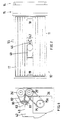
- the apparatus 10 comprises number of interactive mechanisms mounted on a frame 11. These mechanisms include a spindle assembly 12 which carries a roll 13 of heat sealable plastics film in the form of a flat tube T.
- the tube T is fed from the roll to a drive roller assembly 14 located at what will be called the feed end of the frame. For clarity only two rolls 24, 25 of this assembly are shown in Figure 1.
- the drive roller assembly 14 feeds the tube T past a heat sealing and cut-off mechanism 15 and over an assembly of endless belts 17 mounted between drums 18, 19.
- the drum 18 is located adjacent the mechanism 15 and the drum 19 is located adjacent the opposite end of the frame.
- a tube opening mechanism 16 is located between the drums 18, 19.
- the spindle assembly 12 comprises a spindle 21 provided with bearings on which are mounted a cardboard tube located at the centre of the roll 13. The roll thus rotates about the spindle.
- the spindle also carries disc shaped plates 22 mounted at each end of the roll. The plates rest on cross members 23 mounted on the frame 11. The tube T can thus feed freely off the roll and the spindle assembly can be lifted off the cross members for easy replacement of the roll 13.
- the drive roller assembly 14 comprises upper and lower drive rolls 24, 25 mounted, in the present example, in bearing blocks 27, 28 of self lubricating plastics material such as TeflonTM.
- the lower roll is driven through a sprocket chain 75 by an electric motor/gear box assembly indicated at 26.
- the upper roll is geared to the lower roll.
- the bearing blocks are mounted in vertical slide rails 29, 29a fixed to plates mounted on the frame.
- Compression springs 31 are mounted in recesses in the bearing blocks and tend to force the bearing blocks apart.
- the blocks are retained in place by toggles 32.
- the inner end of each toggle is provided with a pin 60 which is hooked into a recess adjacent the upper end of each inner slide rail 29.
- each toggle is drawn downwardly by an over-centre catch arrangement.
- This comprises a screw threaded catch 61 which engages the lower end of a leg 62 pivoted at 63 to a handle 64.
- the handle is in turn pivoted at 65 to the toggle.
- the length of the leg and catch assembly can be adjusted by turning the catch 61 in the leg 62.
- the catch has a T shaped head 66 which, when the handle is raised, engages a hook 67 mounted on the frame 11.
- the upper roll in turn bears on the lower roll 25 with a pressure which can be altered by adjusting the length of the legs 62.
- the toggles When the toggles are released the upper roll 24 is lifted by the springs 31 thus enabling the leading end of a tube T from a fresh roll 13 to be passed between the rolls 24, 25.
- the adjustability of the catch assemblies is important to enable the apparatus to handle film of varying characteristics.
- the pressure applied to each end of the rolls can be independently adjusted. This is important since it enables the direction in which the tube is fed out of the rolls to be accurately adjusted.
- the heat sealing and cut-off mechanism 15 comprises a guillotine-like blade 33 mounted on a cross bar 34.
- Upwardly projecting studs 35 are fixed on the cross bar and slide in a cross plate 36 mounted on the frame 11.
- a washer plate 37, an air bag 39, springs 38 and a block 41 are slidably mounted over the studs.
- the air bag is connected through a connector 39a by suitable pipe work (not shown) to a source of compressed air.
- a conventional, electrically operated shut off valve mounted in the pipe work controls the supply of air to the air bag.
- Two clamping bars 40 are mounted on the lower face of the block 41 and located one on either side of the cross bar 34.
- the cross bar 34 is located in a recess 41a in the block.
- An aluminium plate 42 is mounted on the frame 11 below the cross bar 34.
- the plate has an upper face 43 which is aligned with the line of contact between the drive rolls 24, 25.
- a nichrome ribbon 44 sandwiched between two layers of TeflonTM tape is laid on the face 43 directly underneath the inner clamping bar 40.
- the nichrome wire is connected to a source of electrical power through a switching arrangement which will be discussed in greater detail below.
- the upper bights of the belts 17 collectively constitute a moving surface S at the top of the frame.
- the drums 18, 19 are positioned so that this surface S lies in substantially the same plane as the upper face 43 of the plate 42.
- the drum 19 is located at a higher level than the drum 18 so that the surface S slopes upwardly from the tube feeding end of the frame.
- the drum 18 is driven through a sprocket chain 75a by the same motor/gear box assembly 26 that drives the drive roll 24, the speed of the surface S being equal to or greater than the peripheral speed of the roll 24. Consequently the tube T encounters no friction as it advances across the top of the frame; moreover the belts tend to keep it advancing in a straight line until the leading edge of the tube T arrives at the tube opening assembly 16.
- the assembly 16 is located between the two centre belts 17.
- the assembly 16 comprises a plate 70 on which are mounted a proximity sensor 46; a vacuum head 47 connected through a flexible hose to a vacuum pump 48; and a bag opening head 49 connected to a source of compressed air (not shown).
- the vacuum head is located between the mechanism 15 and the bag opening head and the nozzle 47a of the vacuum head is positioned flush with or just below the moving surface S.
- the proximity sensor senses the arrival of the leading edge of the tube T, the drive roller mechanism is stopped and the heat sealing and cut-off mechanism 15 is actuated (as will be further described below).
- the vacuum head is also actuated.
- the lower layer of film in the tube T is sucked against the nozzle 47a.
- the nozzle is preferably of substantial area, in the present example, about 12 sq. cm.
- the lower layer of film, where it is sucked against the nozzle, is drawn away from the upper layer. This materially assists the separation of the two layers and reduces the likelihood of the lower layer becoming detached from the vacuum nozzle.
- the suction of the vacuum head is controlled by means of a butterfly valve in the throat of the head.
- the butterfly valve is mounted on a shaft one end of which is connected to a lever 50.
- the butterfly valve is operated by a pneumatic ram 51 connected to the lever 50.
- the ram 51 is connected through pipe work (not shown) to a source of compressed air through a second conventional electrically actuated shut-off valve.
- the bag opening head 49 comprises a nozzle 52 connected to a source of compressed air through pipe work (not shown). Yet another conventional electrically actuated shut-off valve in the pipe work controls the supply or air to the nozzle 52.
- the nozzle 52 is mounted in the lower end of an upwardly inclined open ended sleeve 53.
- the assembly functions as a venturi; i.e. when air emerges from the nozzle 52 it draws further air through the lower end of the sleeve.
- the shut-off valve is closed until, following the arrival of the leading edge of the tube T at the proximity sensor 46, the heat sealing and cut-off mechanism 15 and the vacuum head have been actuated as described above.
- the air emerging from the upper end of the sleeve 53 is directed at the leading edge and lifts the upper layer of film at the mouth of what is now a bag in the tube T away from the lower layer. The mouth of the bag is thus automatically opened.
- a bracket 72 carrying rollers 74 is mounted on the plate 70.
- the rollers run on a track 54 in the form of a stainless steel pipe located under the belts 17.
- the plate 70 is provided with a handle portion 55 which projects through a slot in the frame 11 for this purpose.
- a brake 76 which bears on the track for locking the plate 70 in position.
- the brake is mounted on an L-shaped lever 78 which is pivoted to the handle 55. A tension spring connected to the lever urges the brake into contact with the track. The brake is released by lifting the portion 78a of the lever which is located under the handle 55.
- the proximity sensor 46 is of conventional light actuated type and is located between the vacuum head and the bag opening head. It could also be located inside the vacuum head.
- electronic circuitry which includes a timing device and a kick operated master control switch indicated schematically at 56 it is interconnected to the various mechanisms described above. These mechanisms are electronically controlled and their sequence of operation will now be described.
- the bag opening head 49 is first moved to a desired position on the track 54. It is assumed that a new roll 13 of film is mounted on the spindle 21.
- drive rolls 24, 25 and belts 17 will not be started until the kick switch 56 is actuated.
- the roll 24 is raised and the tube T is initially drawn off the roll by hand and fed through the drive rolls 24, 25.
- the roll 24 is lowered and clamped in position.
- the operator stands at the end of the apparatus opposite the tube feed end and actuates the kick switch 56. This starts the drive rolls and the belts 17.
- the tube T is fed by the rolls through the space 45 and along the belts 17.
- the proximity sensor senses the arrival of the leading edge of the tube T the drive roller mechanism is stopped and the vacuum pump is switched on.
- the heat sealing and cut-off mechanism is actuated to form a bag.
- the butterfly valve controlling the vacuum head 47 is opened and the lower layer of film in the bag is sucked against the nozzle of the vacuum head 47.
- the shut-off valve for the nozzle 52 of the bag opening head is opened, causing the mouth of the bag to be opened by the ensuing air blast.
- the joint of meat (or other article to be packaged) is placed in the bag. This is assisted by the downward slope of the belts.
- the bagged joint of meat is removed and the cycle is started again by actuating the kick switch.
- the tube T may sometimes adhere to the clamping bar 40 above the nichrome wire. It must then be detached in order to ensure that the tube advances properly. For this purpose the drive rolls are momentarily reversed after the cut off operation. The tube is thus pulled back a distance of perhaps 1 cm, ensuring that it is detached from the clamping bar 40. It is then advanced again until the leading edge reaches the proximity sensor as already described.
- the vacuum at the head may then be controlled simply by operating the butterfly valve.
- FIG. 6 A modified arrangement for the drive rolls is shown in Figure 6.
- the drive rolls 24', 25' are substantially similar those already described as is the mechanism for driving them.
- a pair of drums 80, 81 is mounted on the frame between the drive rolls and the plate 42.
- Endless belts 82 are mounted between the roll 24' and the drum 80 and also between the roll 25' and the drum 81.
- the rolls and drums are positioned so that there is a substantially flat gap 83 between the upper and lower sets of belts which gap is substantially coplanar with the upper face 43 of the plate 42.
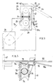
- the modified apparatus 10' shown in Figures 7 and 8 includes a loading device 100 which is of assistance in loading a joint of meat (particularly a heavy joint such as a large cut of beef) into a bag.
- the loading device comprises a rack consisting of four mutually parallel polished stainless steel rods 102 cantilevered from a bar 103.
- the bar comprises a horizontal centre portion 104 and outer portions 105 which project angularly upwardly from each end of the centre portion.
- the inner two rods join the bar at the ends of the centre portion and the outer rods join the bar at the ends of the outer portions.
- the outer rods are thus mounted at a higher level than the inner rods. A joint of meat which slides along the rods thus tends to be cradled centrally on the rack.
- the loading device further comprises a mounting bracket which is mounted on the end of the frame 11' of the apparatus 10'.
- the bracket includes a horizontally disposed arm 106.
- a vertically disposed spigot 107 depends from the bar 103 and is pivotably mounted in the outer end of the arm 106.
- the rack is thus capable of swivelling about a vertical axis. In the position shown in the drawing the rack is disposed so that the rods project towards the open mouth of a bag B which has been formed on the apparatus 10'. This facilitates the loading of a joint of meat from the rack into the bag.
- the rack can however be swivelled to a loading position (shown in dotted outline at 108) in which the rods are aligned with a conveyor (not shown) which feed joints of meat to the machine.
- a loading position shown in dotted outline at 108
- the rods are aligned with a conveyor (not shown) which feed joints of meat to the machine.
- the loading of joints of meat from the conveyor onto the rack is thus facilitated.
- a pair of plates 120 is provided at the top of the frame with a longitudinally disposed slot 122 therebetween.
- the belts 17' are mounted above the plates.
- a pneumatic ram 90 is mounted on the frame 11' below the plates 120 with its axis parallel to slot 122.
- the ram is preferably of the so called "rodless cylinder” type having a carriage 91 which runs along the body 92 of the ram.
- a suitable ram is model MYC25G700 supplied by SMC Corp of Tokyo, Japan.
- a vacuum head 47' is mounted on the carriage. The vacuum head projects through the slot 122. It may be noted that the bag opening head 49' is mounted on the arm 107.
- Actuation of the ram 90 adjusts the position of the vacuum head.
- the positioning of the ram can be determined by microswitches.
- two such microswitches 94, 95 are used but more could be provided. They are fixed to handles 96, 97 which are slidably mounted on a rail 98 under the ram.
- the position of the microswitch 94 determines the length of a short bag and the position of the microswitch 95 determines the length of a long bag.
- the microswitches are actuated by a trigger 99 mounted on the carriage 92.
- a kick switch 56' is operated for making a short bag and a separate kick switch 56'' is provided for making a long bag. Operation of the kickswitch 56' disenables the microswitch 95 and operation of the kickswitch 56'' disenables the microswitch 94.
- the carriage (as will become clear) is fully advanced and the vacuum head is at the extreme end of its travel (to the right in Figure 8).
- the kickswitch 56' When, say, the kickswitch 56' is operated, the carriage retracts until the trigger 99 actuates the microswitch 94. This causes the drive rollers to feed the tube until its leading edge is sensed by the sensor 46'.
- the vacuum head and the heat sealing and cut-off mechanisms are activated to form a short bag B.
- the bag opening head 49' is activated and the carriage 91 is advanced.
- the bag B is thus carried towards the loading device 100 while it is being opened.
- the bag and the air issuing from the head 49' are moving in opposite directions, assisting the opening of the bag.
- the rods 102 are positioned so that, when the head 47' reaches the limit of its travel to the right, the ends of the rods project into the open end of the bag.
- the bag is drawn by hand over the cut of meat on the rack.
- the rack is then swivelled so that the rack is located over a removal conveyor onto which the bagged cut of meat is discharged.
- the cycle can be repeated from this point by again operating the kickswitch 56'. If, alternatively, the kickswitch 56'' is operated, the machine will make a long bag. The bag lengths can be altered by repositioning the microswitches.
- the vacuum head 47' incorporates a perforated grid (which can be seen in Figure 8) to increase the effective area of the nozzle against which the lower layer of the tube is sucked.
- the proximity sensor 46' is incorporated in the vacuum head.
- Either apparatus 10, 10' may be provided with various additional features to increase its utility. For example it is likely that at least one device will be required to reduce or eliminate static electricity which occurs in the tube T. Such devices are known and do not need to be described in detail. One such device is shown schematically at 110.
- Either apparatus 10, 10' can be designed so that it can be used (a) to make open-ended tubular packages; (b) to make unopened bags or packages; and (c) to produce bags or packages uninterruptedly.
- These respective functions can be achieved by incorporating in the control circuitry switches or the like which disenable the heat sealing ribbon 44; the bag opening head 47, 47'; and which by-pass the kickswitches 56, 56', 56''.
- a printing device may be mounted at a suitable location such as between the spindle assembly 12 and the drive roller assembly 14. Suitable printing devices are known per se, one such being sold under the name DATO/PACKTM marketed by Image Jet Printing Pte Ltd of Singapore. Another feature which may be provided is a counting device to count the number of bags produced by the apparatus and/or the length of tubular film used from each roll. Counting devices of this kind are also known per se.
- the belts shown in the apparatus 10 are flat.
- the belts 17' shown in the apparatus 10' are of round cross section.
- the apparatus is suitable for packaging meat in shrink-type packaging.
- the apparatus can be used to form a package which is open at both ends.
- the heat sealing mechanism can be inactivated or dispensed with.
Claims (10)
- Ein Gerät das in jener Art verwendet wird um Verpackungen aus einem Vorrat von flexiblem laminar Verpackungsmaterial in Form eines verlängerten Films (T) in einer Verpackungsoperation herzustellen, in der Artikel verpackt werden können sowie sie hergestellt werden, indem das Gerät aus einer filmeinführenden Vorrichtung besteht (14) und einer Filmabschneidevorrichtung (16) die so betrieben werden kann, daß die besagte Verpackungen hergestellt werden indem nacheinander der vordere Abschnitt des Films vom Vorrat eingeführt wird, und dann der besagte vordere Abschnitt vom Vorrat abgetrennt wird, dadurch gekennzeichnet, daß das Gerät eine Kontrollvorrichtung (46, 56, 70-78, 46', 90, 94-95, 56'-56'') aufweist, um den Vorgang der filmeinführenden Vorrichtung zu kontrollieren, dessen Kontrollvorrichtung einfach verstellbar ist und somit die filmeinführende Vorrichtung dazu veranlaßt, die Länge eines jeden besagten vorderen Abschnitts zu variieren, so daß es so hergestellt ist, um der Länge des zu verpackenden Artikels zu entsprechen.
- Ein Gerät gemäß Anspruch 1, dadurch gekennzeichnet, daß die Kontrollvorrichtung ein Beförderungsmittel (70, 47) und eine Vorrichtung aufweist, die das Beförderungsmittel in Position bringt, mit einem regulierbaren Abstand zur filmeinführenden Vorrichtung, einer Wahrnehmungsvorrichtung (46, 46') die auf dem Beförderungsmittel montiert ist, welche mit einem Signal versehen ist, das nach Feststellung der Ankunft des besagten vorderen Abschnitts an dem Beförderungsmittel, und eine betriebsstoppende Vorrichtung, die so eingerichtet ist, daß sie dem besagten Signal entspricht, um die Operation der filmeinführenden Vorrichtung zu unterbrechen.
- Ein Gerät gemäß Anspruch 1 oder Anspruch 2, dadurch gekennzeichnet, daß die Kontrollvorrichtung einen von einem Bediener betätigten Schalter (56, 56'-56'') aufweist um die Operation der filmeinführenden Vorrichtung auszulösen.
- Ein Gerät gemäß Anspruch 2 oder Anspruch 3, dadurch gekennzeichnet, daß das Beförderungsmittel beweglich auf die Schiene (54) montiert ist, und die Vorrichtung die das Beförderungsmittel in Position bringt, besteht aus einer von einem Bediener ausgelösten Bremsvorrichtung (76-78) die das Beförderungsmittel auf der Schiene in Position hält.
- Ein Gerät gemäß Anspruch 2 oder Anspruch 3, dadurch gekennzeichnet, daß die Vorrichtung die das Beförderungsmittel in Position bringt, aus einem Stoßheber (90) besteht mit dem das Beförderungsmittel verbunden ist, und der Kontrollvorrichtung die das Beförderungsmittel in Position bringt indem sie den Stoßheber vor- oder zurückschiebt.
- Ein Gerät gemäß einem der Ansprüche 2 bis 5, dadurch gekennzeichnet, daß es mit mindestens zwei Endlosbändern (17, 17') ausgestattet ist die gemeinsam eine bewegliche Oberfläche (S) darstellen, auf der die besagten vorderen Abschnitte des Films gestützt werden sowie sie sich auf das Beförderungsband zubewegen.
- Ein Gerät gemäß einem der Ansprüche 2 bis 6, dadurch gekennzeichnet, daß das Beförderungsmittel mit einem Ansauggerät (47, 47') ausgestattet ist das so angebracht ist, daß es eine Saugwirkung auf die erste Schicht des besagten vorderen Filmabschnitts ausübt, und somit eine Vorrichtung darstellt, die eine zweite Schicht von der ersten trennt.
- Ein Gerät gemäß einem der Ansprüche 1 bis 7, dadurch gekennzeichnet, daß es mit einer Hitzschweißvorrichtung (44) neben der Abschneidevorrichtung ausgestattet ist, das die hintere Kante des vorderen Filmabschnitts verschweißt.
- Ein Gerät gemäß einem der Ansprüche 1 bis 8, dadurch gekennzeichnet, daß die filmeinführende Vorrichtung zwei Rollen aufweist (24-25, 24'-25') die den Film an der Abschneidevorrichtung und einer Vorrichtung die zusehends die Rollen rückwärts laufen läßt nachdem die Abschneidevorrichtung aktiviert wurde, vorbeiführt, so daß die nach vorne zeigende Kante des Vorrats die durch die Aktivierung der Abschneidevorrichtung gebildet wurde, sich von der Abschneidevorrichtung zurücksieht, bevor sie vorwärts, an der Abschneidevorrichtung vorbeigeführt werden kann.
- Eine Methode zur Herstellung von Verpackungen aus einem Vorrat von flexiblem laminar Verpackungsmaterial in Form einen verlängerten Films (T) für eine Verpackungsoperation in der die Artikel verpackt werden können, sowie sie hergestellt werden, indem das Gerät aus einer filmeinführenden Vorrichtung besteht (14) und einer Filmabschneidevorrichtung (33) die so betrieben werden kann, daß die besagte Verpackungen hergestellt werden indem nacheinander der vordere Abschnitt des Films vom Vorrat eingeführt wird, und dann der besagte vordere Abschnitt vom Vorrat abgetrennt wird, dadurch gekennzeichnet, daß das Gerät eine Kontrollvorrichtung (46, 56, 70-78, 46', 90, 94-95, 56'-56'') aufweist, um den Vorgang der filmeinführenden Vorrichtung zu kontrollieren, dessen Kontrollvorrichtung einfach verstellbar ist, und somit die filmeinführende Vorrichtung dazu veranlaßt, die Länge eines jeden besagten vorderen Abschnitts zu variieren, so daß es so hergestellt ist, um der Länge des zu verpackenden Artikels zu entsprechen.
Applications Claiming Priority (3)
| Application Number | Priority Date | Filing Date | Title |
|---|---|---|---|
| NZ239153 | 1991-07-26 | ||
| NZ239153A NZ239153A (en) | 1991-07-26 | 1991-07-26 | Packaging apparatus; flattened tube stock cut and sealed at selected |
| PCT/EP1992/001624 WO1993002924A1 (en) | 1991-07-26 | 1992-07-20 | Packaging apparatus |
Publications (2)
| Publication Number | Publication Date |
|---|---|
| EP0595905A1 EP0595905A1 (de) | 1994-05-11 |
| EP0595905B1 true EP0595905B1 (de) | 1995-07-19 |
Family
ID=19923680
Family Applications (1)
| Application Number | Title | Priority Date | Filing Date |
|---|---|---|---|
| EP92915712A Revoked EP0595905B1 (de) | 1991-07-26 | 1992-07-20 | Verpackungsvorrichtung |
Country Status (6)
| Country | Link |
|---|---|
| EP (1) | EP0595905B1 (de) |
| AT (1) | ATE125220T1 (de) |
| AU (1) | AU672952B2 (de) |
| DE (1) | DE69203604T2 (de) |
| NZ (1) | NZ239153A (de) |
| WO (1) | WO1993002924A1 (de) |
Cited By (1)
| Publication number | Priority date | Publication date | Assignee | Title |
|---|---|---|---|---|
| DE102007023328A1 (de) | 2007-05-16 | 2008-11-20 | Anders Agil Gmbh | Warmfleischverpackungsvorrichtung und Verfahren |
Families Citing this family (6)
| Publication number | Priority date | Publication date | Assignee | Title |
|---|---|---|---|---|
| WO1994022723A1 (en) * | 1993-03-26 | 1994-10-13 | Machinery Developments Limited | Packaging apparatus |
| AU742380B3 (en) * | 1993-03-26 | 2001-11-22 | Machinery Developments Limited | Packaging apparatus |
| AU742328B3 (en) * | 1993-03-26 | 2001-11-22 | Machinery Developments Limited | Packaging apparatus |
| AU742332B3 (en) * | 1993-03-26 | 2001-11-22 | Machinery Developments Limited | Packaging apparatus |
| WO1994026596A1 (en) * | 1993-05-06 | 1994-11-24 | Trigon Industries Limited | Continuously forming and presenting bags for packaging |
| DE19549618C2 (de) * | 1995-10-27 | 2001-09-06 | Windmoeller & Hoelscher | Saugersteuerung II |
Citations (1)
| Publication number | Priority date | Publication date | Assignee | Title |
|---|---|---|---|---|
| GB1256729A (de) * | 1968-08-09 | 1971-12-15 |
Family Cites Families (4)
| Publication number | Priority date | Publication date | Assignee | Title |
|---|---|---|---|---|
| US3161002A (en) * | 1961-12-26 | 1964-12-15 | Smith & Nephew Plastics | Packaging machines |
| CH441724A (it) * | 1965-02-22 | 1967-08-15 | Centra Anstalt | Macchina per la fabbricazione e l'erogazione automatica di sacchetti in materia plastica ad una apparecchiatura |
| US3908343A (en) * | 1974-10-07 | 1975-09-30 | Vac Pac Mfg Co | Imbricated bag loading machine |
| US4346546A (en) * | 1978-10-16 | 1982-08-31 | Sidney Tasker | Automatic flexible container fabricating machine |
-
1991
- 1991-07-26 NZ NZ239153A patent/NZ239153A/en unknown
-
1992
- 1992-07-20 AT AT92915712T patent/ATE125220T1/de not_active IP Right Cessation
- 1992-07-20 DE DE69203604T patent/DE69203604T2/de not_active Expired - Fee Related
- 1992-07-20 WO PCT/EP1992/001624 patent/WO1993002924A1/en not_active Application Discontinuation
- 1992-07-20 EP EP92915712A patent/EP0595905B1/de not_active Revoked
- 1992-07-20 AU AU23269/92A patent/AU672952B2/en not_active Withdrawn - After Issue
Patent Citations (1)
| Publication number | Priority date | Publication date | Assignee | Title |
|---|---|---|---|---|
| GB1256729A (de) * | 1968-08-09 | 1971-12-15 |
Cited By (1)
| Publication number | Priority date | Publication date | Assignee | Title |
|---|---|---|---|---|
| DE102007023328A1 (de) | 2007-05-16 | 2008-11-20 | Anders Agil Gmbh | Warmfleischverpackungsvorrichtung und Verfahren |
Also Published As
| Publication number | Publication date |
|---|---|
| DE69203604T2 (de) | 1996-04-25 |
| NZ239153A (en) | 1993-12-23 |
| EP0595905A1 (de) | 1994-05-11 |
| WO1993002924A1 (en) | 1993-02-18 |
| AU2326992A (en) | 1993-03-02 |
| AU672952B2 (en) | 1996-10-24 |
| DE69203604D1 (de) | 1995-08-24 |
| ATE125220T1 (de) | 1995-08-15 |
Similar Documents
| Publication | Publication Date | Title |
|---|---|---|
| US5618252A (en) | Packaging apparatus | |
| US4219988A (en) | Automatic high-speed wrapping machine | |
| US4899520A (en) | Packaging apparatus and method | |
| US4470589A (en) | Method and apparatus for feeding and laminating sheets | |
| US5467676A (en) | Automatic roll wrapper removing apparatus and method | |
| JPS5940684B2 (ja) | ロ−ル包装装置 | |
| EP0595905B1 (de) | Verpackungsvorrichtung | |
| US6802271B2 (en) | Automatic border sewing system | |
| EP1465808B1 (de) | Vorrichtung zum siegeln der überlappenden ränder eines folienschlauches | |
| US3597895A (en) | Packaging method and machine | |
| EP1008543B1 (de) | Vorrichtung zum Formen einer Spleissverbindung in einer Papierbahn | |
| US3938299A (en) | Packaging system and method | |
| JPH0725526A (ja) | 製造機械におけるストリップ材料の交換方法 | |
| US3886026A (en) | Label applying apparatus | |
| EP0947428A1 (de) | Auspackvorrichtung | |
| US5389190A (en) | Apparatus and method for applying a twist-tie to a packaging container | |
| KR100769851B1 (ko) | 리드프레임 자동 포장 장치 | |
| US3577910A (en) | Plastic strapping machine | |
| KR20170136334A (ko) | 파우치 제조장치 | |
| JPH06191697A (ja) | ウェブをスプールに巻き取るための装置および方法 | |
| CA2240947A1 (en) | Folding device and bag making and positioning machine | |
| JP3186566B2 (ja) | 軟質帯状材の巻取装置 | |
| JP2928253B2 (ja) | Ptp包装充填機におけるフィルム自動セッティング及び自動継ぎ装置 | |
| CN219006179U (zh) | 一种裁剪装置 | |
| US4557712A (en) | Apparatus for laying tube or web sections into a folded Z-shaped form |
Legal Events
| Date | Code | Title | Description |
|---|---|---|---|
| PUAI | Public reference made under article 153(3) epc to a published international application that has entered the european phase |
Free format text: ORIGINAL CODE: 0009012 |
|
| 17P | Request for examination filed |
Effective date: 19940214 |
|
| AK | Designated contracting states |
Kind code of ref document: A1 Designated state(s): AT BE CH DE DK ES FR GB GR IT LI LU MC NL SE |
|
| 17Q | First examination report despatched |
Effective date: 19940513 |
|
| GRAA | (expected) grant |
Free format text: ORIGINAL CODE: 0009210 |
|
| AK | Designated contracting states |
Kind code of ref document: B1 Designated state(s): AT BE CH DE DK ES FR GB GR IT LI LU MC NL SE |
|
| PG25 | Lapsed in a contracting state [announced via postgrant information from national office to epo] |
Ref country code: NL Free format text: LAPSE BECAUSE OF FAILURE TO SUBMIT A TRANSLATION OF THE DESCRIPTION OR TO PAY THE FEE WITHIN THE PRESCRIBED TIME-LIMIT Effective date: 19950719 Ref country code: IT Free format text: LAPSE BECAUSE OF FAILURE TO SUBMIT A TRANSLATION OF THE DESCRIPTION OR TO PAY THE FEE WITHIN THE PRESCRIBED TIME-LIMIT;WARNING: LAPSES OF ITALIAN PATENTS WITH EFFECTIVE DATE BEFORE 2007 MAY HAVE OCCURRED AT ANY TIME BEFORE 2007. THE CORRECT EFFECTIVE DATE MAY BE DIFFERENT FROM THE ONE RECORDED. Effective date: 19950719 Ref country code: GR Free format text: LAPSE BECAUSE OF FAILURE TO SUBMIT A TRANSLATION OF THE DESCRIPTION OR TO PAY THE FEE WITHIN THE PRESCRIBED TIME-LIMIT Effective date: 19950719 Ref country code: DK Effective date: 19950719 Ref country code: BE Effective date: 19950719 Ref country code: AT Effective date: 19950719 |
|
| REF | Corresponds to: |
Ref document number: 125220 Country of ref document: AT Date of ref document: 19950815 Kind code of ref document: T |
|
| PG25 | Lapsed in a contracting state [announced via postgrant information from national office to epo] |
Ref country code: MC Free format text: LAPSE BECAUSE OF NON-PAYMENT OF DUE FEES Effective date: 19950731 Ref country code: LU Free format text: LAPSE BECAUSE OF NON-PAYMENT OF DUE FEES Effective date: 19950731 |
|
| REF | Corresponds to: |
Ref document number: 69203604 Country of ref document: DE Date of ref document: 19950824 |
|
| PG25 | Lapsed in a contracting state [announced via postgrant information from national office to epo] |
Ref country code: SE Effective date: 19951019 |
|
| PG25 | Lapsed in a contracting state [announced via postgrant information from national office to epo] |
Ref country code: ES Free format text: LAPSE BECAUSE OF FAILURE TO SUBMIT A TRANSLATION OF THE DESCRIPTION OR TO PAY THE FEE WITHIN THE PRESCRIBED TIME-LIMIT Effective date: 19951020 |
|
| ET | Fr: translation filed | ||
| NLV1 | Nl: lapsed or annulled due to failure to fulfill the requirements of art. 29p and 29m of the patents act | ||
| PLBQ | Unpublished change to opponent data |
Free format text: ORIGINAL CODE: EPIDOS OPPO |
|
| PLBI | Opposition filed |
Free format text: ORIGINAL CODE: 0009260 |
|
| PLBF | Reply of patent proprietor to notice(s) of opposition |
Free format text: ORIGINAL CODE: EPIDOS OBSO |
|
| 26 | Opposition filed |
Opponent name: W.R. GRACE & CO.-CONN. Effective date: 19960419 |
|
| PLBF | Reply of patent proprietor to notice(s) of opposition |
Free format text: ORIGINAL CODE: EPIDOS OBSO |
|
| PLBF | Reply of patent proprietor to notice(s) of opposition |
Free format text: ORIGINAL CODE: EPIDOS OBSO |
|
| PGFP | Annual fee paid to national office [announced via postgrant information from national office to epo] |
Ref country code: GB Payment date: 19980713 Year of fee payment: 7 |
|
| PGFP | Annual fee paid to national office [announced via postgrant information from national office to epo] |
Ref country code: FR Payment date: 19980729 Year of fee payment: 7 |
|
| PGFP | Annual fee paid to national office [announced via postgrant information from national office to epo] |
Ref country code: DE Payment date: 19980828 Year of fee payment: 7 |
|
| PGFP | Annual fee paid to national office [announced via postgrant information from national office to epo] |
Ref country code: CH Payment date: 19980907 Year of fee payment: 7 |
|
| PLAW | Interlocutory decision in opposition |
Free format text: ORIGINAL CODE: EPIDOS IDOP |
|
| PLAW | Interlocutory decision in opposition |
Free format text: ORIGINAL CODE: EPIDOS IDOP |
|
| PG25 | Lapsed in a contracting state [announced via postgrant information from national office to epo] |
Ref country code: GB Free format text: LAPSE BECAUSE OF NON-PAYMENT OF DUE FEES Effective date: 19990720 |
|
| PG25 | Lapsed in a contracting state [announced via postgrant information from national office to epo] |
Ref country code: LI Free format text: LAPSE BECAUSE OF NON-PAYMENT OF DUE FEES Effective date: 19990731 Ref country code: CH Free format text: LAPSE BECAUSE OF NON-PAYMENT OF DUE FEES Effective date: 19990731 |
|
| RDAH | Patent revoked |
Free format text: ORIGINAL CODE: EPIDOS REVO |
|
| RDAG | Patent revoked |
Free format text: ORIGINAL CODE: 0009271 |
|
| STAA | Information on the status of an ep patent application or granted ep patent |
Free format text: STATUS: PATENT REVOKED |
|
| GBPC | Gb: european patent ceased through non-payment of renewal fee |
Effective date: 19990720 |
|
| REG | Reference to a national code |
Ref country code: CH Ref legal event code: PL |
|
| 27W | Patent revoked |
Effective date: 19991129 |
|
| REG | Reference to a national code |
Ref country code: FR Ref legal event code: ST |