EP0595617B1 - Endlos-Förderband - Google Patents
Endlos-Förderband Download PDFInfo
- Publication number
- EP0595617B1 EP0595617B1 EP93308563A EP93308563A EP0595617B1 EP 0595617 B1 EP0595617 B1 EP 0595617B1 EP 93308563 A EP93308563 A EP 93308563A EP 93308563 A EP93308563 A EP 93308563A EP 0595617 B1 EP0595617 B1 EP 0595617B1
- Authority
- EP
- European Patent Office
- Prior art keywords
- conveyor belt
- bottom member
- endless conveyor
- foraminous bottom
- link
- Prior art date
- Legal status (The legal status is an assumption and is not a legal conclusion. Google has not performed a legal analysis and makes no representation as to the accuracy of the status listed.)
- Expired - Lifetime
Links
Images


Classifications
-
- B—PERFORMING OPERATIONS; TRANSPORTING
- B65—CONVEYING; PACKING; STORING; HANDLING THIN OR FILAMENTARY MATERIAL
- B65G—TRANSPORT OR STORAGE DEVICES, e.g. CONVEYORS FOR LOADING OR TIPPING, SHOP CONVEYOR SYSTEMS OR PNEUMATIC TUBE CONVEYORS
- B65G21/00—Supporting or protective framework or housings for endless load-carriers or traction elements of belt or chain conveyors
- B65G21/16—Supporting or protective framework or housings for endless load-carriers or traction elements of belt or chain conveyors for conveyors having endless load-carriers movable in curved paths
- B65G21/18—Supporting or protective framework or housings for endless load-carriers or traction elements of belt or chain conveyors for conveyors having endless load-carriers movable in curved paths in three-dimensionally curved paths
-
- B—PERFORMING OPERATIONS; TRANSPORTING
- B65—CONVEYING; PACKING; STORING; HANDLING THIN OR FILAMENTARY MATERIAL
- B65G—TRANSPORT OR STORAGE DEVICES, e.g. CONVEYORS FOR LOADING OR TIPPING, SHOP CONVEYOR SYSTEMS OR PNEUMATIC TUBE CONVEYORS
- B65G2207/00—Indexing codes relating to constructional details, configuration and additional features of a handling device, e.g. Conveyors
- B65G2207/24—Helical or spiral conveying path
Definitions
- This invention relates to endless conveyor belts, in particular for the treatment of particulate solid material, for example to re-order or dry tobacco.
- a gas treatment apparatus in the form of a self-stacking spiral conveyor where products on the conveyor are treated by heat transfer from a treatment gas, such as refrigerating, freezing, or heating.
- the conditioning means for the treatment gas may be a heat exchanger which cools or heats the treatment gas before it circulates around and through the bed of conveyed product.
- Frigoscandia self-stacking spiral conveying machine e.g., a Model GCP 42 selfstacking spiral freezer supplied by Frigoscandia Food Process Systems AB of Helsingborg, Sweden
- This apparatus by virtue of its self-stacking spiral design and gas recirculation fans, channels the majority of gas flow downward through the multiple tiers of the conveyor, which are carrying the product.
- the resistance to gas flow from the rods and springs was very low and essentially invariable.
- the fixed resistance to gas flow precluded varying the resistance to gas flow in the vertical direction as one tool to control the gas flow pattern within the conveyor stack.
- the invention aims to provide a conveyor belt that may be configured to carry minute particles such as are found in packed bed applications.
- an endless conveyor belt comprising a plurality of articulated conveyor links which enable the belt to follow a predetermined path, each conveyor link comprising two spacer members substantially perpendicular to the plane of the conveyor link, a fixed rod fixedly connected to both spacer members, an articulation rod fixedly connected to both spacer members and linked to an adjacent conveyor link's spacer member, a foraminous bottom member fixedly attached to one of or both the fixed rod and the articulation rod, the foraminous bottom member extending along a portion of the width of the endless conveyor belt link, and shaped such that the foraminous bottom member impedes neither the conveyor belt's radial nor vertical articulation, and an upstanding flange at an end of each foraminous bottom member, wherein the flange of each link is shaped such that it does not impede the conveyor belt's articulation.
- a foraminous bottom member has the advantage of being able to control the total resistance of the conveyor belt to gas flow in the vertical direction within the conveyor stock.
- the upstanding flange has the advantage of providing a means to form a trough within the conveyor belt, so that packed beds or other conveyed products may be placed within the confines of the trough and not contact the sides of the conveyor belt.
- a preferred embodiment of the invention is used with a gas treatment apparatus which comprises a housing having an infeed and outfeed.
- An endless conveyor belt runs through the infeed into the housing, follows a spiral path comprising several superimposed tiers in the housing, and runs through the outfeed opening of the housing.
- the conveyor belt has links that are relatively moveable, enabling the conveyor belt to follow a predetermined path, with each link having a fixed rod and an articulation rod and a spacer member at each transverse side of the conveyor belt for supporting the conveyor belt in an overlying tier.
- the two rods are attached to the side spacers.
- the articulation rod is also attached to the adjacent conveyor link's spacer members with one end attached through a hole in the spacer member and with one end of the articulation rod free to slide in a slot in the adjacent conveyor link's other side spacer.
- a foraminous bottom member extends along a portion of the width of the conveyor link, preferably the foraminous bottom member extends along nearly the whole transverse width of the conveyor link, and is attached to both rods.
- Each foraminous bottom member may and preferably does overlap an adjacent foraminous bottom member. However, such overlap should not impair the belt links from articulating.
- the endless conveyor belt in its spiral path forms a conveyor stack in the form of a hollow cylinder having a perforated inner wall and a perforated outer wall comprising the spacing members and defining a vertical tube bounded by the spacing members comprising the inner wall of the hollow cylinder.
- the perforations in the foraminous bottom members are dimensioned according to the size of the particles to be transported, and the number of perforations are chosen according to the gas flow desired to pass through the perforated bottom members.
- the perforations in the bottom member may be of one or more shapes and may be arranged in a regular or an irregular pattern.
- the region of the foraminous bottom member overlaps the adjacent foraminous bottom member and the region of the adjacent foraminous bottom member that is overlapped by the first bottom member may be given more perforations so as to decrease the resistance to gas flow in these zones of overlap.
- the regions of the foraminous bottom member immediately above the fixed rods may be perforation-free to increase the strength of the foraminous bottom member or to merely reduce the manufacturing cost for perforations.
- bends used to form the foraminous bottom member may be replaced with creases to increase the rigidity of the foraminous bottom member.
- each foraminous bottom member may at its side ends have upstanding flanges overlapping the upstanding flanges of an adjacent foraminous bottom member in the same manner as the foraminous bottom members themselves overlap.
- the flanges may also be perforated to increase gas flow in the radial direction.
- the conveyor belt will be formed like a trough enabling transport of very minute particles such as are found in packed bed applications.
- Another application of upstanding flanges is to act as an impediment to gas flow along the longitudinal direction of the endless conveyor belt so as to increase gas flow in other directions such as in the vertical direction through the packed bed of conveyed product.
- the upstanding flanges would be attached at least partially transverse to the direction of belt travel.
- An embodiment of the invention is a modification to a self-stacking spiral conveyor belt that traverses through a circulating treatment gas in the housing of a gas treatment apparatus.
- the modification allows treatment of much smaller-dimension discrete products than had been possible with open-web belts of the prior art.
- the modification also makes it possible to treat a packed bed of conveyed product rather than a single layer of relatively large discrete products.
- a preferred embodiment of the invention also provides additional control over the gas flow within the gas treatment apparatus. This is achieved without impairing the articulation of the belt links into the spiral.
- Prior art conveyor belts of this type are either self-stacking, i.e., the side links are in the form of side plates serving as spacers, the upper edge portions of which are adapted to engage the lower edge portions of the overlying turn of the conveyor belt so as to support this turn, or supported by separate rails following the spiral path of the conveyor belt.
- the gas-treatment apparatus 15 shown generally in FIG. 1, comprises a housing 16 having an infeed opening 17 and an outfeed opening 18.
- An endless conveyor belt 19 runs through the infeed opening 17 into the housing 16.
- the endless conveyor belt 19 follows along at least a portion of its length a spiral path comprising several superimposed tiers to form a conveyor stack 20.
- the endless conveyor belt 19 then exits the housing 16 through the outfeed opening 18.
- the endless conveyor belt 19 returns to the infeed opening 17.
- the return is not shown, but could occur inside or outside of the housing.
- FIG. 1 also shows the gas flow pattern from the fan 21, down through the conveyor stack 20, and back through the conditioning means 22, before returning to the fan 21.
- the endless conveyor belt 19 is of the self-supporting type and consists of a plurality of conveyor links 23 shown in FIG. 2.
- the conveyor links 23 are mutually moveable in such a way that the belt can follow the path illustrated in FIG. 1. More precisely, each conveyor link 23 of the conveyor belt 19 comprises two spacer members 24, one at each side of two rods 25 and 26.
- the fixed rod 25 is fixedly attached at both spacer members 24, and the articulation rod 26 fixedly connected to both spacer members 24, and also connected to the adjacent conveyor link's spacer members 24, at one adjacent spacer member by a hole and at the other adjacent spacer member by a slot.
- Exemplifying embodiments of the conveyor belt 19 that may be used in the apparatus according to the present invention are disclosed in e.g., U.S. Patents No. 3,938,651, 4,603,776 and 4,941,567, all assigned to Frigoscandia Contracting AB of Sweden and incorporated herein by reference.
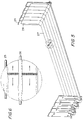
- FIGS. 3 and 4 give additional detail of a single foraminous bottom member 27 through which the air flow may pass.
- Each foraminous bottom member 27 is spot welded or otherwise fixedly attached to both rods 25 and 26 and fits between the two spacer members 24.
- the leading edge of the foraminous bottom member may be curled downward to wrap around a portion of the circumference of the articulation rod 25.
- the trailing edge of each foraminous bottom members 27 may overlap the curved leading edge of the successive foraminous bottom member 27 and is shaped so as to allow the endless conveyor belt 19 to freely articulate into the conveyor stack 20.
- the term articulate is defined as bending or other relative-motion at jointed, slotted or other types of connections.
- the foraminous bottom members 27 will overlap substantially in the same manner as the side spacers 24.
- a plenum zone 29 is formed by the trailing ridge 30 of the foraminous bottom member 27 as the one foraminous bottom member overlaps the successive foraminous bottom member.
- This plenum zone 29 allows gas to flow through perforations in the overlapping region of the foraminous bottom member 27 and then through the perforations in the overlapped region of the successive foraminous bottom member 27 or through the gap between the overlapping and overlapped foraminous bottom members 27.
- the foraminous bottom member 27 is illustrated in FIGS. 2 and 3 with the optional flanges 28, which are particularly useful when the conveyed material is a packed bed or otherwise likely to contact and potentially impede the articulation of the side spacers.
- the foraminous bottom member 27 does not necessarily extend the full distance between spacers members 24 and is not necessarily attached to either spacer members 24, however, for additional strength, the foraminous bottom member 27 may be sized so that the leading edge of the foraminous bottom member 27 is approximately the size of the gap between spacer members 24 and the foraminous bottom member could be attached to the spacer members 24.
- the flanges 28 may be bent inward at the trailing edge so the that the flanges overlap and do not impede the motion of the articulating conveyor links.
- the height of the flanges 28 is less than the height of the side spacers 24 so that the overlapping portion of the flanges 28 does not extend beyond the height of side spacers 24 while both the foraminous bottom members 27 and the side spacers 24 are bending in the vertical plane.
- the foraminous bottom member 27 is designed to allow adequate gas flow while retaining the conveyed material.
- FIG. 2 shows one embodiment of the foraminous bottom member made from standard punch plate and carefully bent into the appropriate shape.
- FIGS. 5 and 6 illustrate another embodiment of the foraminous bottom member 27 with side flanges 28.
- the foraminous bottom member 27 may be punched with one millimeter diameter holes densely packed in a triangular pattern with 1.7 millimeter centers.
- FIG. 6 shows a sample of the hole pattern with arrows to indicate that the holes would be added along the entire transverse length of the foraminous bottom member 27.
- the holes are not added in the portion of the bottom member above the rods 25 and 26.
- Gas flow in the region above the rods 25 and 26 could be increased by one of several methods, including drilling holes through the rods, or placing a thick weld or other spacer to raise the foraminous bottom member 27 above the rods 25 and 26 so as to make perforations of the foraminous bottom member 27 effective above the rods 25 and 26.
- the density of perforations may be increased in the foraminous bottom members adjacent to the zones above the rods 25 and 26.
- the foraminous bottom members 27 are perforated such that the conveyor belt may transport particles of a minute size.
- the widths of the perforations are dimensioned according to the size of the particles to be transported, and the number of perforations are chosen according to the air flow desired to pass through the bottom plates.
- the combination of perforation size and perforation density gives considerable latitude in the resistance of the foraminous bottom member 27 to gas flow in the vertical direction. Slots or other non-circular shapes could be substituted for holes if the alternative shape provided an advantage in retaining conveyed material for a given application or if these shapes allowed reduced fabrication costs.
- the treatment gas in a packed bed application is more uniformly distributed when the resistance to gas flow of the structure supporting the packed bed is a significant fraction of the resistance of the packed bed to gas flow.
- the ability to modify the gas flow resistance is important for a packed bed application.
- the bottom plates may be perforated with various perforation sizes or perforation densities or perforation patterns to influence gas flow patterns. For example, progressively larger holes and or progressively denser hole patterns could be used across the transverse dimension of the foraminous bottom member to bias the gas flow to the portion of the foraminous bottom member on the inner radius of the conveyor stack.
- This biasing of gas flow could be employed to equalize the treatment of a packed bed of conveyed product since the depth of the packed bed increases across the transverse dimension of the foraminous bottom member proportionately to the amount of overlap along the foraminous bottom member as the conveyor belt articulates into a circle if the feed is uniformly distributed on the straight inlet section.
- the feed of conveyed material could be biased so that the depth of the conveyed bed is essentially uniform after the belt articulates.
- the flanges may be perforated to increase radial flow.
- creases 31-36 may be added to the bent foraminous bottom members 27 and associated upright flanges 28 as a means for increasing the rigidity of the foraminous bottom members.
- spiral should be read broadly and not limited to a circular spiral.
- the invention is equally applicable to oval spirals, spirals with relatively large segments of straight conveyor belt so that the spiral is essentially in the shape of an ellipse, a triangle, rectangle, pentagon, or other polygon, a double spiral where the endless conveyor belt articulates in first one direction then in the opposite direction, and to any other shape that requires the conveyor belt to both ascend and curve, or to descend and curve, such as overlaid figure eights, and spirals with successive tiers that are either progressively smaller or progressively larger than the preceding tiers.
- a figure eight would require the conveyor belt to bend to both the right and to the left, but the present invention would be applicable to such a conveyor belt as well.
- the present invention could be applied generally to any conveying system that bends into curves and changes elevation.
- the use for such a belt could be unrelated to any gas treatment apparatus, for example, assembly lines, food processing conveyors, inspection conveyors, or select and convey operations from warehouses.
- the perforation openings in the foraminous bottom members could be of any shape that allows the passage of gas through the foraminous bottom member, including round openings, slit openings, polygonal openings, irregular shaped openings, and opening that have a change in shape or size from the top surface of the foraminous bottom member to the bottom surface of the foraminous bottom member.
Landscapes
- Engineering & Computer Science (AREA)
- Mechanical Engineering (AREA)
- Structure Of Belt Conveyors (AREA)
- Belt Conveyors (AREA)
- Chain Conveyers (AREA)
- Manufacture And Refinement Of Metals (AREA)
- Combined Means For Separation Of Solids (AREA)
- Air Transport Of Granular Materials (AREA)
- Preliminary Treatment Of Fibers (AREA)
Claims (14)
- Endloses Transportband (19), umfassend eine Vielzahl von gelenkig angeordneten Transportgliedern (23), durch die das Band einem vorbestimmten Laufweg folgen kann, wobei jedes Transportglied zwei im wesentlichen senkrecht zu der Ebene des Transportgliedes angeordnete Abstandselemente (24), einen befestigten, fest mit beiden Abstandselementen verbundenen Stab (25), einen fest mit beiden Abstandselementen verbundenen und mit einem Abstandselement eines benachbarten Transportglieds verbundenen Gelenkstab (26), und ein eine Vielzahl von Löchern aufweisendes, fest an einem oder an beiden von dem befestigten Stab und dem Gelenkstab angebrachtes Bodenelement (27) umfaßt, wobei das eine Vielzahl von Löchern aufweisende Bodenelement längs eines Abschnitts der Breite des Gliedes des endlosen Transportbandes verläuft und so geformt ist, daß das eine Vielzahl von Löchern aufweisende Bodenelement weder die radiale noch die vertikale Gelenkigkeit des Transportbandes beeinträchtigt, sowie einen aufrechtstehenden Flansch (28) an einem Ende von jedem eine Vielzahl von Löchern aufweisenden Bodenelement, wobei der Flansch jedes Gliedes so geformt ist, daß er die Gelenkigkeit des Transportbandes nicht beeinträchtigt.
- Endloses Transportband nach Anspruch 1, worin das endlose Transportband selbsttragend ist.
- Endloses Transportband nach Anspruch 1, worin das endlose Transportband von einer Schiene gehalten wird.
- Endloses Transportband nach einem vorhergehenden Anspruch, worin ein Abschnitt des vorbestimmten Laufweges eine Wegstrecke ist, für die eine radiale Gelenkigkeit oder eine vertikale Gelenkigkeit oder beides erforderlich ist.
- Endloses Transportband nach Anspruch 4, worin ein Abschnitt des vorbestimmten Laufweges eine wendelförmige Wegstrecke ist.
- Endloses Transportband nach Anspruch 5, worin der Abschnitt eine selbststapelnde Helix ist.
- Endloses Transportband nach einem vorhergehenden Anspruch, worin das eine Vielzahl von Löchern aufweisende Bodenelement jedes Gliedes an dem befestigten Stab und dem Gelenkstab des Gliedes angebracht ist.
- Endloses Transportband nach einem vorhergehenden Anspruch, worin das eine Vielzahl von Löchern aufweisende Bodenelement jedes Gliedes eine Länge in der Laufrichtung des Transportbandes aufweist, die so groß ist, daß es das eine Vielzahl von Löchern aufweisende Bodenelement eines benachbarten Gliedes zumindest teilweise überlappt.
- Endloses Transportband nach einem vorhergehenden Anspruch, worin der aufrechtstehende Flansch so angeordnet ist, daß er den Strom des transportierten Materials oder den Gasstrom in Längsrichtung vermindert.
- Endloses Transportband nach einem vorhergehenden Anspruch, worin die Flansche (28) der eine Vielzahl von Löchern aufweisenden Bodenelemente so perforiert sind, daß sie den radialen Gasstrom vergrößern.
- Endloses Transportband nach einem vorhergehenden Anspruch, worin die Flansche eines eine Vielzahl von Löchern aufweisenden Bodenelementes die Flansche eines benachbarten, eine Vielzahl von Löchern aufweisenden Bodenelementes in der gleichen Weise überlappen, in der sich die eine Vielzahl von Löchern aufweisenden Bodenelemente überlappen.
- Endloses Transportband nach einem vorhergehenden Anspruch, worin das eine Vielzahl von Löchern aufweisende Bodenelement eine Schwelle in dem Abschnitt aufweist, der das Bodenelement eines benachbarten Gliedes überlappt und eine Luftkammer bildet, die den Gasstrom durch die sich überlappenden und überlappten Bereiche der eine Vielzahl von Löchern aufweisenden Bodenelemente erleichtert.
- Endloses Transportband nach einem vorhergehenden Anspruch, worin die Abmessungen der Perforationen oder die Anzahl der Perforationen oder beide in dem eine Vielzahl von Löchern aufweisenden Bodenelement jedes Gliedes unterschiedlich sind.
- Endloses Transportband nach einem vorhergehenden Anspruch, worin das eine Vielzahl von Löchern aufweisende Bodenelement jedes Gliedes fest an den jeweiligen seitlichen Abstandselementen angebracht ist und die Befestigungsweise die Gelenkigkeit des Transportbandes nicht beeinträchtigt.
Applications Claiming Priority (2)
| Application Number | Priority Date | Filing Date | Title |
|---|---|---|---|
| US969761 | 1992-10-30 | ||
| US07/969,761 US5346057A (en) | 1992-10-30 | 1992-10-30 | Conveyor belt for treatment of particulate solid material |
Publications (2)
| Publication Number | Publication Date |
|---|---|
| EP0595617A1 EP0595617A1 (de) | 1994-05-04 |
| EP0595617B1 true EP0595617B1 (de) | 1997-04-16 |
Family
ID=25515964
Family Applications (1)
| Application Number | Title | Priority Date | Filing Date |
|---|---|---|---|
| EP93308563A Expired - Lifetime EP0595617B1 (de) | 1992-10-30 | 1993-10-27 | Endlos-Förderband |
Country Status (14)
| Country | Link |
|---|---|
| US (1) | US5346057A (de) |
| EP (1) | EP0595617B1 (de) |
| JP (1) | JPH06211331A (de) |
| CN (1) | CN1043210C (de) |
| AT (1) | ATE151717T1 (de) |
| AU (1) | AU669408B2 (de) |
| BR (1) | BR9307463A (de) |
| DE (1) | DE69309847T2 (de) |
| DK (1) | DK0595617T3 (de) |
| ES (1) | ES2100475T3 (de) |
| GR (1) | GR3023669T3 (de) |
| RU (1) | RU2108952C1 (de) |
| WO (1) | WO1994010067A1 (de) |
| ZA (1) | ZA938106B (de) |
Families Citing this family (35)
| Publication number | Priority date | Publication date | Assignee | Title |
|---|---|---|---|---|
| US5460260A (en) * | 1994-06-22 | 1995-10-24 | York International Corporation | Helical conveyor |
| SE505637C2 (sv) * | 1995-10-24 | 1997-09-22 | Frigoscandia Equipment Ab | Transportband |
| US5702245A (en) * | 1996-03-20 | 1997-12-30 | Stein, Inc. | Conveyor for processing equipment having gas flow compensation |
| AT404741B (de) * | 1997-03-11 | 1999-02-25 | Huyck Austria | Textiler gurt |
| US5974692A (en) * | 1998-05-06 | 1999-11-02 | Frigoscandia Equipment Ab | Apparatus for air-treatment of products |
| US7940966B2 (en) | 2000-11-24 | 2011-05-10 | U-Systems, Inc. | Full-field breast image data processing and archiving |
| US7556602B2 (en) * | 2000-11-24 | 2009-07-07 | U-Systems, Inc. | Breast cancer screening with adjunctive ultrasound mammography |
| US7615008B2 (en) * | 2000-11-24 | 2009-11-10 | U-Systems, Inc. | Processing and displaying breast ultrasound information |
| US7597663B2 (en) | 2000-11-24 | 2009-10-06 | U-Systems, Inc. | Adjunctive ultrasound processing and display for breast cancer screening |
| US6766901B2 (en) | 2001-07-19 | 2004-07-27 | Habasit Ag | Snap-on side guards |
| US20040020749A1 (en) * | 2001-09-14 | 2004-02-05 | Brian Wood | Spiral immersion conveyor system, and method for use |
| US6796420B2 (en) * | 2001-10-23 | 2004-09-28 | Richard K. Byrne | Self-stacking conveyor belt and method |
| US7107899B2 (en) * | 2002-01-10 | 2006-09-19 | Nothum Jr Robert G | Spiral oven, heat delivery, enclosure and drive |
| US6976369B2 (en) * | 2002-01-10 | 2005-12-20 | Nothum Jr Robert G | Spiral freezer, refrigeration delivery, enclosure and drive |
| DE20303097U1 (de) | 2003-02-26 | 2003-05-15 | Heinen Freezing GmbH, 26316 Varel | Selbststapelnder Gurt |
| US6811023B1 (en) * | 2003-05-22 | 2004-11-02 | Laitram, L.L.C. | Modular trough conveyor belt and modules |
| ES2274170T3 (es) * | 2003-07-17 | 2007-05-16 | Ashworth Jonge Poerink B.V. | Eslabon para la union de vastagos de una cinta tranportadora arrolada en espiral alrededor de un tambor conducido, cinta transportadora y sistema tansportador con dichos eslabones de union. |
| US7258226B2 (en) * | 2003-10-14 | 2007-08-21 | The Boc Group, Inc. | Self-stacking spiral conveyor with modular drive system |
| US6811021B1 (en) | 2003-11-06 | 2004-11-02 | Laitram, L.L.C. | Plastic conveyor belt modules with unitary sideguards |
| US7237376B1 (en) | 2005-03-11 | 2007-07-03 | R. J. Reynolds Tobacco Company | Chain repair system |
| US20070169630A1 (en) * | 2006-01-20 | 2007-07-26 | David Auyoung | Thermal processing chamber and conveyor belt for use therein and method of processing product |
| WO2007140242A2 (en) * | 2006-05-24 | 2007-12-06 | Span Tech Llc | Side-flexing conveyor chain with pivoting slats and related methods |
| DE102007031730A1 (de) * | 2007-07-06 | 2009-01-08 | Alco-Food-Machines Gmbh & Co. Kg | Vorrichtung zur thermischen Behandlung von Lebensmitteln |
| US8578842B2 (en) | 2009-10-12 | 2013-11-12 | Hans van der Ent | Apparatuses and methods for the production of sandwich food items |
| SE535298C2 (sv) * | 2010-12-21 | 2012-06-19 | John Bean Technologies Ab | Förbättrat sidoplattelement för ett länkorgan i ett självstaplande ändlöst transportband |
| CN102914130A (zh) * | 2012-09-24 | 2013-02-06 | 四川南充首创科技开发有限公司 | 双螺旋循环积层化干燥装置 |
| CN103287787B (zh) * | 2013-06-24 | 2016-01-13 | 广西力源宝科技有限公司 | 有机物料发酵用输送带 |
| CN103591786A (zh) * | 2013-10-14 | 2014-02-19 | 镇江众志电力设备有限公司 | 立式旋转烘干系统 |
| US10099859B2 (en) * | 2015-04-15 | 2018-10-16 | Laitram, L.L.C. | Self-stacking spiral modular plastic conveyor belt with intermediate support |
| ITUB20152285A1 (it) * | 2015-07-17 | 2017-01-17 | Magaldi Ind Srl | Sistema di trasporto a nastro per grandi portate di materiale sfuso |
| EP3348942A1 (de) * | 2017-01-17 | 2018-07-18 | Paul Wurth S.A. | Seitenwand eines palettenwagens für eine wanderrostmaschine, palettenwagen mit derartiger seitenwand und verfahren zur umwandlung eines palettenwagens |
| WO2018213404A2 (en) * | 2017-05-17 | 2018-11-22 | Laitram, L.L.C. | Centrifugal dewatering conveyor system |
| RU180129U1 (ru) * | 2018-02-06 | 2018-06-05 | Николай Николаевич Копылов | Звено транспортера |
| RU2688057C1 (ru) * | 2018-03-19 | 2019-05-17 | Иван Евгеньевич Мелехов | Устройство для разделения рядов пиломатериалов в сушильном штабеле |
| CN114906536A (zh) * | 2022-04-29 | 2022-08-16 | 北京华电博远环保设备有限公司 | 一种具有透气功能的平面金属输送带 |
Citations (1)
| Publication number | Priority date | Publication date | Assignee | Title |
|---|---|---|---|---|
| WO1991000233A1 (en) * | 1989-06-27 | 1991-01-10 | Frigoscandia Food Process Systems Ab | Conveyor belt |
Family Cites Families (19)
| Publication number | Priority date | Publication date | Assignee | Title |
|---|---|---|---|---|
| US3123202A (en) * | 1964-03-03 | Slatted-type conveyor | ||
| US1883528A (en) * | 1931-01-17 | 1932-10-18 | Buck Dryer Corp | Conveyer |
| US2823790A (en) * | 1954-07-15 | 1958-02-18 | American Cyanamid Co | Plate conveyor construction |
| GB1132177A (en) * | 1966-03-15 | 1968-10-30 | Frigoscandia A B | Improvements in plant for treating foodstuffs and other products with air |
| SE381241B (sv) * | 1973-03-07 | 1975-12-01 | Frigoscandia Contracting Ab | Transportanordning med ett endlost transportband vilket er anordnat att till en del av sin lengd folja en bana bestaende av ett antal over varandra belegna skruvformigt forlopande varv |
| US4178946A (en) * | 1976-06-25 | 1979-12-18 | Philip Morris Incorporated | Apparatus and method for control of air relative humidity with reduced energy usage in the treatment of tobacco |
| US4089666A (en) * | 1976-06-25 | 1978-05-16 | Philip Morris Incorporated | Method for control of air relative humidity with reduced energy usage |
| DE2950122A1 (de) * | 1979-12-13 | 1981-06-19 | Engelbrecht + Lemmerbrock Gmbh + Co, 4520 Melle | Trocknungsvorrichtung fuer frisch geschnittene halmgueter |
| US4344524A (en) * | 1980-08-21 | 1982-08-17 | Koppers Company, Inc. | Fines removal in horizontal coolers |
| FR2527754B1 (fr) * | 1982-05-28 | 1987-03-20 | Ceric | Perfectionnement aux sechoirs |
| SE434728B (sv) * | 1982-11-26 | 1984-08-13 | Frigoscandia Contracting Ab | Upplagsanordning for uppberande av ett antal det ena over det andra i stapel belegna skruvformigt forlopande varv av ett endlost transportband |
| SE437008B (sv) * | 1982-11-26 | 1985-02-04 | Frigoscandia Contracting Ab | Transportband |
| US4542821A (en) * | 1983-02-22 | 1985-09-24 | Lamb-Weston, Inc. | Hump back conveyor |
| DE3505013C2 (de) * | 1985-02-14 | 1998-02-19 | Oetiker Hans Maschinen | Endlose Lastträgerbahn für Endlosförderer |
| SE452590B (sv) * | 1985-12-27 | 1987-12-07 | Frigoscandia Contracting Ab | Transportband |
| SE458356B (sv) * | 1986-07-24 | 1989-03-20 | Frigoscandia Contracting Ab | Upplagsanordning |
| DE3735402A1 (de) * | 1987-06-01 | 1988-12-15 | Gebr Hennig Gmbh | Spaenefoerderer |
| DE3723591A1 (de) * | 1987-07-16 | 1989-01-26 | Gebr Hennig Gmbh | Spaenefoerderer |
| US4875343A (en) * | 1988-03-14 | 1989-10-24 | Jeppsson E Hakan O | Climate chamber with conveyor |
-
1992
- 1992-10-30 US US07/969,761 patent/US5346057A/en not_active Expired - Fee Related
-
1993
- 1993-10-27 EP EP93308563A patent/EP0595617B1/de not_active Expired - Lifetime
- 1993-10-27 DK DK93308563.1T patent/DK0595617T3/da active
- 1993-10-27 DE DE69309847T patent/DE69309847T2/de not_active Expired - Fee Related
- 1993-10-27 ES ES93308563T patent/ES2100475T3/es not_active Expired - Lifetime
- 1993-10-27 AT AT93308563T patent/ATE151717T1/de not_active IP Right Cessation
- 1993-10-29 BR BR9307463A patent/BR9307463A/pt not_active IP Right Cessation
- 1993-10-29 AU AU54018/94A patent/AU669408B2/en not_active Ceased
- 1993-10-29 ZA ZA938106A patent/ZA938106B/xx unknown
- 1993-10-29 RU RU95109899A patent/RU2108952C1/ru not_active IP Right Cessation
- 1993-10-29 WO PCT/SE1993/000899 patent/WO1994010067A1/en not_active Ceased
- 1993-10-30 CN CN93120745A patent/CN1043210C/zh not_active Expired - Fee Related
- 1993-11-01 JP JP5297445A patent/JPH06211331A/ja active Pending
-
1997
- 1997-06-04 GR GR970401313T patent/GR3023669T3/el unknown
Patent Citations (1)
| Publication number | Priority date | Publication date | Assignee | Title |
|---|---|---|---|---|
| WO1991000233A1 (en) * | 1989-06-27 | 1991-01-10 | Frigoscandia Food Process Systems Ab | Conveyor belt |
Also Published As
| Publication number | Publication date |
|---|---|
| US5346057A (en) | 1994-09-13 |
| DE69309847T2 (de) | 1997-09-18 |
| ES2100475T3 (es) | 1997-06-16 |
| JPH06211331A (ja) | 1994-08-02 |
| CN1043210C (zh) | 1999-05-05 |
| CN1092373A (zh) | 1994-09-21 |
| GR3023669T3 (en) | 1997-09-30 |
| BR9307463A (pt) | 1999-08-24 |
| DK0595617T3 (da) | 1997-08-04 |
| ATE151717T1 (de) | 1997-05-15 |
| AU669408B2 (en) | 1996-06-06 |
| RU2108952C1 (ru) | 1998-04-20 |
| AU5401894A (en) | 1994-05-24 |
| ZA938106B (en) | 1994-06-10 |
| EP0595617A1 (de) | 1994-05-04 |
| WO1994010067A1 (en) | 1994-05-11 |
| DE69309847D1 (de) | 1997-05-22 |
Similar Documents
| Publication | Publication Date | Title |
|---|---|---|
| US5346057A (en) | Conveyor belt for treatment of particulate solid material | |
| EP0333565B1 (de) | Klimakammer mit Fördereinrichtung | |
| EP0595618B1 (de) | Vorrichtung zur Behandlung von festen Stoffen | |
| KR101253562B1 (ko) | 모듈형 플라스틱 컨베이어 벨트, 및 그의 에지 모듈 | |
| EP0966392B1 (de) | Gelenkiger endlosförderer zum bewegen auf einer dreidimensionalen bahn | |
| CA1302337C (en) | Conveyors | |
| US5190143A (en) | Conveyor belt | |
| EP1980504B1 (de) | Modulares Kunststoffförderband mit hoher Trägerfestigkeit | |
| RU95109899A (ru) | Бесконечная транспортерная лента | |
| PL200918B1 (pl) | Taśma przenośnika oraz komora klimatyczna zawierająca taśmę przenośnika | |
| EP1174371B1 (de) | Förderband mit modularem Radius | |
| US6098792A (en) | Conveyor belt | |
| AU692112B2 (en) | Conveyor belt | |
| WO1991004209A1 (en) | Conveyor belt with stacking plates | |
| EP4526233A1 (de) | Verschleissfeste metallbandförderer mit drahtgitter |
Legal Events
| Date | Code | Title | Description |
|---|---|---|---|
| PUAI | Public reference made under article 153(3) epc to a published international application that has entered the european phase |
Free format text: ORIGINAL CODE: 0009012 |
|
| AK | Designated contracting states |
Kind code of ref document: A1 Designated state(s): AT BE CH DE DK ES FR GB GR IE IT LI LU MC NL PT SE |
|
| 17P | Request for examination filed |
Effective date: 19940516 |
|
| 17Q | First examination report despatched |
Effective date: 19950309 |
|
| GRAG | Despatch of communication of intention to grant |
Free format text: ORIGINAL CODE: EPIDOS AGRA |
|
| GRAH | Despatch of communication of intention to grant a patent |
Free format text: ORIGINAL CODE: EPIDOS IGRA |
|
| GRAH | Despatch of communication of intention to grant a patent |
Free format text: ORIGINAL CODE: EPIDOS IGRA |
|
| GRAA | (expected) grant |
Free format text: ORIGINAL CODE: 0009210 |
|
| AK | Designated contracting states |
Kind code of ref document: B1 Designated state(s): AT BE CH DE DK ES FR GB GR IE IT LI LU MC NL PT SE |
|
| REF | Corresponds to: |
Ref document number: 151717 Country of ref document: AT Date of ref document: 19970515 Kind code of ref document: T |
|
| REG | Reference to a national code |
Ref country code: CH Ref legal event code: NV Representative=s name: BOVARD AG PATENTANWAELTE Ref country code: CH Ref legal event code: EP |
|
| REF | Corresponds to: |
Ref document number: 69309847 Country of ref document: DE Date of ref document: 19970522 |
|
| ET | Fr: translation filed | ||
| REG | Reference to a national code |
Ref country code: ES Ref legal event code: FG2A Ref document number: 2100475 Country of ref document: ES Kind code of ref document: T3 |
|
| REG | Reference to a national code |
Ref country code: IE Ref legal event code: FG4D Free format text: 73325 |
|
| REG | Reference to a national code |
Ref country code: PT Ref legal event code: SC4A Free format text: AVAILABILITY OF NATIONAL TRANSLATION Effective date: 19970417 |
|
| REG | Reference to a national code |
Ref country code: DK Ref legal event code: T3 |
|
| REG | Reference to a national code |
Ref country code: GR Ref legal event code: FG4A Free format text: 3023669 |
|
| PLBE | No opposition filed within time limit |
Free format text: ORIGINAL CODE: 0009261 |
|
| 26N | No opposition filed | ||
| PGFP | Annual fee paid to national office [announced via postgrant information from national office to epo] |
Ref country code: DK Payment date: 19980911 Year of fee payment: 6 |
|
| PGFP | Annual fee paid to national office [announced via postgrant information from national office to epo] |
Ref country code: AT Payment date: 19980915 Year of fee payment: 6 |
|
| PGFP | Annual fee paid to national office [announced via postgrant information from national office to epo] |
Ref country code: MC Payment date: 19980917 Year of fee payment: 6 |
|
| PGFP | Annual fee paid to national office [announced via postgrant information from national office to epo] |
Ref country code: IE Payment date: 19980924 Year of fee payment: 6 |
|
| PGFP | Annual fee paid to national office [announced via postgrant information from national office to epo] |
Ref country code: PT Payment date: 19980925 Year of fee payment: 6 Ref country code: CH Payment date: 19980925 Year of fee payment: 6 |
|
| PGFP | Annual fee paid to national office [announced via postgrant information from national office to epo] |
Ref country code: ES Payment date: 19981009 Year of fee payment: 6 |
|
| PGFP | Annual fee paid to national office [announced via postgrant information from national office to epo] |
Ref country code: BE Payment date: 19981016 Year of fee payment: 6 |
|
| PGFP | Annual fee paid to national office [announced via postgrant information from national office to epo] |
Ref country code: GR Payment date: 19981022 Year of fee payment: 6 |
|
| PGFP | Annual fee paid to national office [announced via postgrant information from national office to epo] |
Ref country code: LU Payment date: 19981124 Year of fee payment: 6 |
|
| PG25 | Lapsed in a contracting state [announced via postgrant information from national office to epo] |
Ref country code: LU Free format text: LAPSE BECAUSE OF NON-PAYMENT OF DUE FEES Effective date: 19991027 Ref country code: IE Free format text: LAPSE BECAUSE OF NON-PAYMENT OF DUE FEES Effective date: 19991027 Ref country code: DK Free format text: LAPSE BECAUSE OF NON-PAYMENT OF DUE FEES Effective date: 19991027 Ref country code: AT Free format text: LAPSE BECAUSE OF NON-PAYMENT OF DUE FEES Effective date: 19991027 |
|
| PG25 | Lapsed in a contracting state [announced via postgrant information from national office to epo] |
Ref country code: ES Free format text: LAPSE BECAUSE OF NON-PAYMENT OF DUE FEES Effective date: 19991028 |
|
| PG25 | Lapsed in a contracting state [announced via postgrant information from national office to epo] |
Ref country code: LI Free format text: LAPSE BECAUSE OF NON-PAYMENT OF DUE FEES Effective date: 19991031 Ref country code: GR Free format text: LAPSE BECAUSE OF NON-PAYMENT OF DUE FEES Effective date: 19991031 Ref country code: CH Free format text: LAPSE BECAUSE OF NON-PAYMENT OF DUE FEES Effective date: 19991031 Ref country code: BE Free format text: LAPSE BECAUSE OF NON-PAYMENT OF DUE FEES Effective date: 19991031 |
|
| BERE | Be: lapsed |
Owner name: PHILIP MORRIS PRODUCTS INC. Effective date: 19991031 |
|
| PG25 | Lapsed in a contracting state [announced via postgrant information from national office to epo] |
Ref country code: PT Free format text: LAPSE BECAUSE OF NON-PAYMENT OF DUE FEES Effective date: 20000430 Ref country code: MC Free format text: LAPSE BECAUSE OF NON-PAYMENT OF DUE FEES Effective date: 20000430 |
|
| REG | Reference to a national code |
Ref country code: CH Ref legal event code: PL |
|
| REG | Reference to a national code |
Ref country code: PT Ref legal event code: MM4A Free format text: LAPSE DUE TO NON-PAYMENT OF FEES Effective date: 20000430 |
|
| REG | Reference to a national code |
Ref country code: IE Ref legal event code: MM4A |
|
| REG | Reference to a national code |
Ref country code: GB Ref legal event code: IF02 |
|
| REG | Reference to a national code |
Ref country code: DK Ref legal event code: EBP |
|
| REG | Reference to a national code |
Ref country code: ES Ref legal event code: FD2A Effective date: 20001113 |
|
| PGFP | Annual fee paid to national office [announced via postgrant information from national office to epo] |
Ref country code: NL Payment date: 20080923 Year of fee payment: 16 Ref country code: IT Payment date: 20080923 Year of fee payment: 16 Ref country code: FR Payment date: 20080922 Year of fee payment: 16 |
|
| PGFP | Annual fee paid to national office [announced via postgrant information from national office to epo] |
Ref country code: GB Payment date: 20080919 Year of fee payment: 16 |
|
| PGFP | Annual fee paid to national office [announced via postgrant information from national office to epo] |
Ref country code: DE Payment date: 20080923 Year of fee payment: 16 |
|
| PGFP | Annual fee paid to national office [announced via postgrant information from national office to epo] |
Ref country code: SE Payment date: 20080918 Year of fee payment: 16 |
|
| REG | Reference to a national code |
Ref country code: NL Ref legal event code: V1 Effective date: 20100501 |
|
| EUG | Se: european patent has lapsed | ||
| REG | Reference to a national code |
Ref country code: FR Ref legal event code: ST Effective date: 20100630 |
|
| PG25 | Lapsed in a contracting state [announced via postgrant information from national office to epo] |
Ref country code: NL Free format text: LAPSE BECAUSE OF NON-PAYMENT OF DUE FEES Effective date: 20100501 Ref country code: FR Free format text: LAPSE BECAUSE OF NON-PAYMENT OF DUE FEES Effective date: 20091102 Ref country code: DE Free format text: LAPSE BECAUSE OF NON-PAYMENT OF DUE FEES Effective date: 20100501 |
|
| PG25 | Lapsed in a contracting state [announced via postgrant information from national office to epo] |
Ref country code: GB Free format text: LAPSE BECAUSE OF NON-PAYMENT OF DUE FEES Effective date: 20091027 |
|
| PG25 | Lapsed in a contracting state [announced via postgrant information from national office to epo] |
Ref country code: IT Free format text: LAPSE BECAUSE OF NON-PAYMENT OF DUE FEES Effective date: 20091027 |
|
| PG25 | Lapsed in a contracting state [announced via postgrant information from national office to epo] |
Ref country code: SE Free format text: LAPSE BECAUSE OF NON-PAYMENT OF DUE FEES Effective date: 20091028 |