EP0594318A1 - Méthode et dispositif pour l'alimentation en carburant d'un moteur à combustion interne - Google Patents
Méthode et dispositif pour l'alimentation en carburant d'un moteur à combustion interne Download PDFInfo
- Publication number
- EP0594318A1 EP0594318A1 EP93307838A EP93307838A EP0594318A1 EP 0594318 A1 EP0594318 A1 EP 0594318A1 EP 93307838 A EP93307838 A EP 93307838A EP 93307838 A EP93307838 A EP 93307838A EP 0594318 A1 EP0594318 A1 EP 0594318A1
- Authority
- EP
- European Patent Office
- Prior art keywords
- fuel
- engine
- mass
- fraction
- air
- Prior art date
- Legal status (The legal status is an assumption and is not a legal conclusion. Google has not performed a legal analysis and makes no representation as to the accuracy of the status listed.)
- Withdrawn
Links
Images

Classifications
-
- F—MECHANICAL ENGINEERING; LIGHTING; HEATING; WEAPONS; BLASTING
- F02—COMBUSTION ENGINES; HOT-GAS OR COMBUSTION-PRODUCT ENGINE PLANTS
- F02D—CONTROLLING COMBUSTION ENGINES
- F02D41/00—Electrical control of supply of combustible mixture or its constituents
- F02D41/02—Circuit arrangements for generating control signals
- F02D41/18—Circuit arrangements for generating control signals by measuring intake air flow
-
- F—MECHANICAL ENGINEERING; LIGHTING; HEATING; WEAPONS; BLASTING
- F02—COMBUSTION ENGINES; HOT-GAS OR COMBUSTION-PRODUCT ENGINE PLANTS
- F02D—CONTROLLING COMBUSTION ENGINES
- F02D41/00—Electrical control of supply of combustible mixture or its constituents
- F02D41/02—Circuit arrangements for generating control signals
- F02D41/04—Introducing corrections for particular operating conditions
- F02D41/047—Taking into account fuel evaporation or wall wetting
-
- F—MECHANICAL ENGINEERING; LIGHTING; HEATING; WEAPONS; BLASTING
- F02—COMBUSTION ENGINES; HOT-GAS OR COMBUSTION-PRODUCT ENGINE PLANTS
- F02D—CONTROLLING COMBUSTION ENGINES
- F02D2200/00—Input parameters for engine control
- F02D2200/02—Input parameters for engine control the parameters being related to the engine
- F02D2200/04—Engine intake system parameters
- F02D2200/0402—Engine intake system parameters the parameter being determined by using a model of the engine intake or its components
Definitions
- the present invention relates to a method of and apparatus for fuelling an internal combustion engine.
- the ratio of air to fuel of the air-fuel mixture inducted into an at least one engine cylinder deviates from the desired value. This may give rise to increased exhaust pollution and difficulty in driving a vehicle powered by the engine.
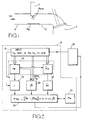
- FIG. 1 of the accompanying drawings schematically illustrates the region around a fuel injector 1.
- the injector 1 is operated to inject a mass of fuel M INJ into an air flow.
- a proportion r of the injected fuel is entrained by the air flow and is transported towards a combustion region 3.
- M iNj r the mass of fuel transported towards the combustion region as a direct consequence of injector operation.
- M1Ni1-r wets a surface 2 within the engine. Consequently a mass of fuel M w accumulates on the surface 2.
- evaporation takes place from the surface 2.
- the amount of fuel that evaporates in a relatively short time interval AT (such that the mass M w is not greatly altered) can be represented by M w ⁇ T/ ⁇ , where ⁇ represents a time constant of evaporation.
- the mass of fuel M F supplied to the combustion region 3 is given by:
- a method of fuelling an internal combustion engine having an inlet manifold and at least one combustion region comprising the steps of:
- the fuel mass is estimated in response to an estimate of air flow into the manifold.
- the air flow may be estimated from throttle position and manifold pressure.
- the air flow is modelled by an air model accounting for temperature and ambient pressure so as to provide an estimate of the mass of the air that is admitted to the at least one combustion region.
- the estimate of air flow into the manifold is a prediction for air flow for a future fuelling event. It is thus possible to use measurements of current engine operating conditions to estimate the actual mass of air that will be admitted into a cylinder when the cylinder is charged with a air-fuel mixture.
- the output of the air model may be compared with measured air flow when the engine is operating under steady state or near steady state conditions.
- the model may be corrected as a result of the comparison.
- the model may then provide reliable estimates of air flow during non-steady state, i.e. transient, operating conditions.
- the model may estimate the amount of air that will be admitted into a cylinder during the next induction stroke of that cylinder.
- the estimate of the fraction of injected fuel that wets the surface is dependent on manifold pressure and a temperature.
- the temperature may be an engine coolant temperature.
- the relation between pressure, temperature and the fraction of fuel that wets the surface is determined by experiment for the type of engine and stored in a memory. The values stored in the memory may be updated during use of the engine.
- the amount of fuel on the surface is estimated from the fuel injection quantity, the estimate of the fraction of injected fuel that wets the surface and the estimate of fuel evaporation from the surface.
- the estimate of the fuel on the surface is regularly updated, for instance at fixed intervals of time or at least for each respective injector operation.
- the mass of fuel evaporated from the surface is estimated from the estimate of fuel on the surface and at least a first variable.
- the first variable is dependent on manifold pressure.
- the estimate of the fraction of injected fuel that wets the surface for given engine operating conditions is updated by sensing the change in the oxygen content of the exhaust gas in response to a known change in fuel injection quantity.
- the known change in fuel injection quantity may be a predetermined change in fuel injection quantity.
- the value of the first variable for given engine operating conditions is updated during periods of engine overrun, that is periods in which fuelling is suspended, for example when the vehicle powered by the engine is descending an incline and the driver has removed his foot from the accelerator pedal.
- the update may be performed by monitoring the change with time of the oxygen content in the exhaust gas to thereby determine the amount of fuel that evaporates from the surface.
- the integral of the amount of fuel evaporated may advantageously be used to check the estimate of the amount of fuel in the fuel film on the surface.
- a fuelling system for an internal combustion engine having an inlet manifold and at least one combustion region comprising:
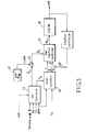
- Data from an engine 10 such as coolant temperature Tw, engine speed RPM, throttle angle ⁇ ), ambient pressure Pa, and ambient temperature Ta are measured by suitable sensors (not shown) on the engine.
- the fuel controller 11 may be embodied by a programmable data processor and conveniently may be included within an engine management system.
- the input data is provided from a data collection and storage means 15 to an air dynamics model 16 to estimate the pressure Pm within an inlet manifold 4 of the engine 10.
- the air dynamics model uses the throttle angle ⁇ , engine speed, and ambient temperature and pressure to estimate what the air pressure will be within a manifold during the next cylinder fuelling event.
- the manifold pressure Pm can be found from:
- Mt is the mass of air past the throttle.
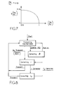
- the flow function g(Pm/Pa) has a value of 0.04 for Pm/Pa less than 0.53 and greater than zero. For values of Pm/Pa greater than 0.53, the value of the flow function is derived from a look-up table. The approximate form of the flow function for values of Pm/Pa greater than 0.53 is shown in Figure 7.
- the discharge co-efficient Cd is stored in a table addressed by air mass flow and throttle angle.
- Ae is related to the throttle angle ⁇ .
- the mass of air Ma inducted into the combustion chamber 3 is calculated from
- This value is also estimated by the air dynamics model 16.
- the manifold pressure Pm is provided to a look-up table 18, along with the measurements of coolant temperature Tw.
- the look-up table provides an estimate of fraction r of injected fuel that does not wet the surface 2.
- the amount of fuel thatwets the surface is M INJ (1-r) where M INJ is the amount of fuel injected into the manifold 4 by the injector 1.
- the estimate of the amount of fuel M w on the surface 2 is held in a memory 19.
- the number of times per second that the injector is operated depends upon the engine speed, so the engine speed datum is used to calculate the amount of fuel on the surface 2.
- the value of M w can be found from at each injection, where ⁇ is defined in equation 7 below, M w (n) is the mass at the nth estimate and M w(n-1) is the mass at the (n-1)th estimate.
- the manifold pressure and temperature are also provided, along with engine speed, to a look-up table 20, or as inputs to a calculation, for providing an estimate of the variable ⁇ , where
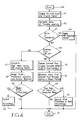
- the look-up tables 18 and 20 and the estimate of Mw are performed by the fuel dynamic model 30 shown in Figure 3.
- M eva p rate of evaporation per unit area.
- evaporation is a surface process, it is proportional to the surface area of the fuel film on the surface 2. Ati is the duration of the air-fuel induction into the cylinder.
- the wetted surface area can be expressed in terms of the fuel mass on the wall 2, the thickness of the film of fuel and fuel density, since where
- Changes in fuel volatility can be compensated for by varying the value of the film thickness S, thereby giving rise to a false surface area to compensate for the changed volatility.
- the mass of air Ma inducted into the cylinder is supplied to a fuel mass calculator 22, for instance based on an air-fuel ratio map 23, so as to estimate the mass of fuel M f that is to be inducted so as to obtain the desired air-fuel ratio.
- a fuel injection controller 25 receives r, ⁇ , M f and M w and calculates the injection quantity M INJ of the fuel to be injected.
- the mass of fuel, M f , delivered to the cylinder is However, the model is used to predict events subsequent to the injector operation, so that mass of fuel on the wall 2 will be
- M wo is the current mass of fuel on the wall.
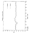
- FIG. 4 shows a flow chart for determining when to perform the updating or r and ⁇ .
- the routine is commenced at step 40.
- the throttle angle is measured at step 41.
- the throttle angle 15 is compared with a previous measurement of throttle angle at step 42 so as to estimate the rate of change of throttle position.
- the rate of change is compared with a first threshold at step 43. If the rate of throttle opening exceeds the first threshold, control is passed to step 44 to activate the fuel controller to control the fuelling through the transient operating conditions. From step 44 control is passed to the finishing step 45 of the routine. If the rate of change of throttle opening is less than the first threshold, control passes from step 43 to step 46 where a check is made to determine if the operating conditions are such that fuelling is suspended.
- Control is passed tostep47 ifthefuelling has not been suspended, thus the engine is running under steady state or near steady state conditions.
- the fuel model calculates the amount of fuel that should be injected.
- An engine base fuelling algorithm also calculates the amount of fuel that should be injected for a given air-fuel ratio. Under steady state conditions loss of fuel to the wall must equal evaporation from the wall, hence the base fuelling algorithm is accurate under steady state conditions.
- An error signal as the difference between the predicted injected fuel and the actual injected fuel masses is formed at step 48. The error is compared with a second threshold at step 49. If the error is greater than the threshold, control is passed to step 50 in initiate an update of r. Otherwise control is passed to step 45. Upon exiting step 50, control passes to step 45.
- Step 50 represents a routine for updating r. Equation 15 can expressed as: which can be re-arranged as where
- Ma mass of air inducted into the combustion chamber
- AFR air-fuel ratio where the subscript i denotes the ith calculation of r.
- the calculated values of r are then averaged over a predetermined number of combustions to eliminate any lag between the amount of fuel injected and the air-fuel ratio measured.
- the corrected values of r are stored in the look-up table 18 addressed by coolant temperature and manifold pressure.
- step 46 If, at step 46, it is determined that the engine is in over-run, that is the fuelling is inhibited, the control is passed to step 51 where measurements of exhaust gas oxygen content are made. This enables air-fuel ratio as a result of evaporation from the surface 2 to be calculated and hence the amount of fuel evaporated from the surface 2 in a fixed period to be estimated at step 52.
- the mass of fuel evaporated from the surface 2 is compared with the value of Mw at step 53, and if the difference is greater than a third threshold, control is passed to step 54 so as to initiate an updating of (3. Measurements can be made over a few unfuelled combustion cycles and an average of (3 can be formed and stored in look-up table 20.
- Figures 5 and 6 show test data for an engine having a fuel system operating according to the present invention, showing how actual air-fuel ratio is maintained in spite of a transient condition between the 20th and 30th cycles.
- the solid line represents the amount of fuel admitted into a cylinder in an engine that was controlled by an intelligent controller.
- the engine had been repeatedly run through the speed transient and the intelligent controller had learnt the required fuel injection quantities to maintain the air-fuel ratio within specified tolerances.
- the intelligent controller does not constitute an embodiment of the present invention.
- the air-fuel ratio within that engine is presented by the solid line in Figure 6.
- the air-fuel ratio deviates significantly as a result of the transient.
- the chain line in Figure 5 shows the fuel mass injected when the engine is controlled by a fuel controller constituting an embodiment of the present invention.
- the extra fuelling applied between 0 and 12 engine cycles is a consequence of the model being started with no knowledge that the engine had been running and consequently an initial value of M W equal to zero.
- the model assumed that fuel would be lost to the surface 2, but very little fuel would evaporate from the surface 2.
- the model quickly establishes an estimate for M w that is close to the actual amount.
- the chain line of Figure 6 shows the resulting air-fuel ratio as a result of the model.
- the air-fuel ratio deviates by only a small amount from its target value.
- the fuel controller of the present invention demonstrably performs better than the intelligent controller. Furthermore the fuel controller of the present invention did not require a plurality of attempts to learn how to control the fuelling.
- Figure 8 is a state transition diagram illustrating the conditions under which updating of variables are performed. (3 is updated when the engine is in overrun (fuel cut off) operation, while r and Cd are updated during steady state operation.
Landscapes
- Engineering & Computer Science (AREA)
- Chemical & Material Sciences (AREA)
- Combustion & Propulsion (AREA)
- Mechanical Engineering (AREA)
- General Engineering & Computer Science (AREA)
- Electrical Control Of Air Or Fuel Supplied To Internal-Combustion Engine (AREA)
- Combined Controls Of Internal Combustion Engines (AREA)
Applications Claiming Priority (2)
| Application Number | Priority Date | Filing Date | Title |
|---|---|---|---|
| GB929222328A GB9222328D0 (en) | 1992-10-23 | 1992-10-23 | Method of and apparatus for fuelling an internal combustion engine |
| GB9222328 | 1992-10-23 |
Publications (1)
| Publication Number | Publication Date |
|---|---|
| EP0594318A1 true EP0594318A1 (fr) | 1994-04-27 |
Family
ID=10723967
Family Applications (1)
| Application Number | Title | Priority Date | Filing Date |
|---|---|---|---|
| EP93307838A Withdrawn EP0594318A1 (fr) | 1992-10-23 | 1993-10-01 | Méthode et dispositif pour l'alimentation en carburant d'un moteur à combustion interne |
Country Status (3)
| Country | Link |
|---|---|
| EP (1) | EP0594318A1 (fr) |
| JP (1) | JPH06200797A (fr) |
| GB (1) | GB9222328D0 (fr) |
Cited By (7)
| Publication number | Priority date | Publication date | Assignee | Title |
|---|---|---|---|---|
| FR2760045A1 (fr) * | 1997-02-25 | 1998-08-28 | Renault | Procede de regulation de la richesse d'un moteur thermique a injection indirecte |
| EP0880644A1 (fr) * | 1996-11-18 | 1998-12-02 | Motorola, Inc. | Procede et dispositif de commande de carburant avec apprentissage en ligne de parametres de compensation de carburant en circuit ouvert |
| EP0984148A2 (fr) * | 1998-08-31 | 2000-03-08 | Ford Global Technologies, Inc. | Système et méthode d'alimentation en carburant |
| WO2000019076A1 (fr) * | 1998-09-25 | 2000-04-06 | Delphi Technologies, Inc. | Compensation de carburant en regime transitoire |
| EP0936351A3 (fr) * | 1998-02-12 | 2001-04-04 | Yamaha Hatsudoki Kabushiki Kaisha | Méthode et dispositif de commande à valeur optimale d'un objet de commande à l'aide d'une commande à apprentisage |
| FR2844307A1 (fr) * | 2002-09-05 | 2004-03-12 | Bosch Gmbh Robert | Procede et dispositif pour determiner la masse de carburant d'un film de paroi lors de l'injection dans la conduite d'aspiration d'un moteur a combustion interne |
| WO2007003642A1 (fr) * | 2005-07-04 | 2007-01-11 | Robert Bosch Gmbh | Procede pour faire fonctionner un moteur a combustion interne |
Citations (7)
| Publication number | Priority date | Publication date | Assignee | Title |
|---|---|---|---|---|
| EP0026643A2 (fr) * | 1979-09-27 | 1981-04-08 | Ford Motor Company Limited | Système de dosage de carburant pour moteur à combustion interne |
| EP0152019A2 (fr) * | 1984-02-01 | 1985-08-21 | Hitachi, Ltd. | Méthode de commande de l'injection de carburant pour un moteur |
| EP0295650A2 (fr) * | 1987-06-17 | 1988-12-21 | Hitachi, Ltd. | Appareil de commande de moteur |
| EP0301548A2 (fr) * | 1987-07-29 | 1989-02-01 | Toyota Jidosha Kabushiki Kaisha | Système d'injection de carburant de moteur à combustion interne |
| WO1990007053A1 (fr) * | 1988-12-14 | 1990-06-28 | Robert Bosch Gmbh | Procede de mesure de carburant |
| US4999781A (en) * | 1989-07-17 | 1991-03-12 | General Motors Corporation | Closed loop mass airflow determination via throttle position |
| US5035225A (en) * | 1989-09-04 | 1991-07-30 | Toyota Jidosha Kabushiki Kaisha | Fuel injection control apparatus of internal combustion engine |
-
1992
- 1992-10-23 GB GB929222328A patent/GB9222328D0/en active Pending
-
1993
- 1993-10-01 EP EP93307838A patent/EP0594318A1/fr not_active Withdrawn
- 1993-10-22 JP JP28615593A patent/JPH06200797A/ja active Pending
Patent Citations (7)
| Publication number | Priority date | Publication date | Assignee | Title |
|---|---|---|---|---|
| EP0026643A2 (fr) * | 1979-09-27 | 1981-04-08 | Ford Motor Company Limited | Système de dosage de carburant pour moteur à combustion interne |
| EP0152019A2 (fr) * | 1984-02-01 | 1985-08-21 | Hitachi, Ltd. | Méthode de commande de l'injection de carburant pour un moteur |
| EP0295650A2 (fr) * | 1987-06-17 | 1988-12-21 | Hitachi, Ltd. | Appareil de commande de moteur |
| EP0301548A2 (fr) * | 1987-07-29 | 1989-02-01 | Toyota Jidosha Kabushiki Kaisha | Système d'injection de carburant de moteur à combustion interne |
| WO1990007053A1 (fr) * | 1988-12-14 | 1990-06-28 | Robert Bosch Gmbh | Procede de mesure de carburant |
| US4999781A (en) * | 1989-07-17 | 1991-03-12 | General Motors Corporation | Closed loop mass airflow determination via throttle position |
| US5035225A (en) * | 1989-09-04 | 1991-07-30 | Toyota Jidosha Kabushiki Kaisha | Fuel injection control apparatus of internal combustion engine |
Cited By (11)
| Publication number | Priority date | Publication date | Assignee | Title |
|---|---|---|---|---|
| EP0880644A1 (fr) * | 1996-11-18 | 1998-12-02 | Motorola, Inc. | Procede et dispositif de commande de carburant avec apprentissage en ligne de parametres de compensation de carburant en circuit ouvert |
| EP0880644A4 (fr) * | 1996-11-18 | 2000-06-07 | Motorola Inc | Procede et dispositif de commande de carburant avec apprentissage en ligne de parametres de compensation de carburant en circuit ouvert |
| FR2760045A1 (fr) * | 1997-02-25 | 1998-08-28 | Renault | Procede de regulation de la richesse d'un moteur thermique a injection indirecte |
| WO1998038424A1 (fr) * | 1997-02-25 | 1998-09-03 | Renault | Procede de regulation de la richesse d'un moteur thermique a injection indirecte |
| EP0936351A3 (fr) * | 1998-02-12 | 2001-04-04 | Yamaha Hatsudoki Kabushiki Kaisha | Méthode et dispositif de commande à valeur optimale d'un objet de commande à l'aide d'une commande à apprentisage |
| US6415273B1 (en) | 1998-02-12 | 2002-07-02 | Yamaha Hatsudoki Kabushiki Kaisha | Method of feed-forward control using control logic with anticipatory learning control |
| EP0984148A2 (fr) * | 1998-08-31 | 2000-03-08 | Ford Global Technologies, Inc. | Système et méthode d'alimentation en carburant |
| EP0984148A3 (fr) * | 1998-08-31 | 2003-01-15 | Ford Global Technologies, Inc. | Système et méthode d'alimentation en carburant |
| WO2000019076A1 (fr) * | 1998-09-25 | 2000-04-06 | Delphi Technologies, Inc. | Compensation de carburant en regime transitoire |
| FR2844307A1 (fr) * | 2002-09-05 | 2004-03-12 | Bosch Gmbh Robert | Procede et dispositif pour determiner la masse de carburant d'un film de paroi lors de l'injection dans la conduite d'aspiration d'un moteur a combustion interne |
| WO2007003642A1 (fr) * | 2005-07-04 | 2007-01-11 | Robert Bosch Gmbh | Procede pour faire fonctionner un moteur a combustion interne |
Also Published As
| Publication number | Publication date |
|---|---|
| JPH06200797A (ja) | 1994-07-19 |
| GB9222328D0 (en) | 1992-12-09 |
Similar Documents
| Publication | Publication Date | Title |
|---|---|---|
| US5526794A (en) | Electronic controller for accurately controlling transient operation of a physical system | |
| US7140356B2 (en) | Engine throttle opening degree area estimation method, as well as engine acceleration detection method and device and engine fuel injection control method and device using the estimation method | |
| US4467770A (en) | Method and apparatus for controlling the air-fuel ratio in an internal combustion engine | |
| JPH0565845A (ja) | エンジン制御方法及びシステム | |
| EP0275507B1 (fr) | Méthode et appareil de commande du rapport air-carburant d'un moteur à combustion à apprentissage | |
| EP0461480B1 (fr) | Méthode et dispositif de commande de l'injection de carburant dans un moteur à combustion interne | |
| JPS6411814B2 (fr) | ||
| US5144933A (en) | Wall flow learning method and device for fuel supply control system of internal combustion engine | |
| US5931136A (en) | Throttle control device and control method for internal combustion engine | |
| EP0594318A1 (fr) | Méthode et dispositif pour l'alimentation en carburant d'un moteur à combustion interne | |
| CN101187341A (zh) | 内燃机的空气量运算装置及燃料控制装置 | |
| US5477832A (en) | Engine fuel control system with fuel distillation point compensation | |
| US4953513A (en) | Engine control apparatus | |
| JPH0530977B2 (fr) | ||
| JP3817648B2 (ja) | 内燃機関の燃料噴射量制御装置 | |
| JP2754568B2 (ja) | 内燃機関の燃料噴射量制御装置 | |
| JP2003120404A (ja) | 内燃機関の制御装置 | |
| JPH09166038A (ja) | 内燃機関のアイドル回転速度学習制御装置 | |
| JPH0742879B2 (ja) | 内燃機関の燃料制御装置 | |
| JPH0833130B2 (ja) | 内燃機関の空燃比の学習制御装置 | |
| JP2582558B2 (ja) | 内燃機関の空燃比の学習制御装置 | |
| JP2962981B2 (ja) | 過渡時空燃比補正噴射時間の制御方法 | |
| JP2548612B2 (ja) | 内燃機関の燃料供給制御装置 | |
| JPH0557423B2 (fr) | ||
| JPH01305146A (ja) | 内燃機関の空燃比の学習制御装置 |
Legal Events
| Date | Code | Title | Description |
|---|---|---|---|
| PUAI | Public reference made under article 153(3) epc to a published international application that has entered the european phase |
Free format text: ORIGINAL CODE: 0009012 |
|
| AK | Designated contracting states |
Kind code of ref document: A1 Designated state(s): DE ES FR GB IT SE |
|
| 17P | Request for examination filed |
Effective date: 19941021 |
|
| 17Q | First examination report despatched |
Effective date: 19950601 |
|
| STAA | Information on the status of an ep patent application or granted ep patent |
Free format text: STATUS: THE APPLICATION IS DEEMED TO BE WITHDRAWN |
|
| 18D | Application deemed to be withdrawn |
Effective date: 19960629 |