EP0594091B1 - Flüssigkeits- und Abrasivmittelzuführung für eine Fluidstrahlschneidanlage - Google Patents
Flüssigkeits- und Abrasivmittelzuführung für eine Fluidstrahlschneidanlage Download PDFInfo
- Publication number
- EP0594091B1 EP0594091B1 EP93116760A EP93116760A EP0594091B1 EP 0594091 B1 EP0594091 B1 EP 0594091B1 EP 93116760 A EP93116760 A EP 93116760A EP 93116760 A EP93116760 A EP 93116760A EP 0594091 B1 EP0594091 B1 EP 0594091B1
- Authority
- EP
- European Patent Office
- Prior art keywords
- cutting head
- connecting arm
- cutting
- abrasive material
- storage container
- Prior art date
- Legal status (The legal status is an assumption and is not a legal conclusion. Google has not performed a legal analysis and makes no representation as to the accuracy of the status listed.)
- Expired - Lifetime
Links
- 238000005520 cutting process Methods 0.000 title claims abstract description 56
- 239000003082 abrasive agent Substances 0.000 title claims abstract description 8
- XLYOFNOQVPJJNP-UHFFFAOYSA-N water Substances O XLYOFNOQVPJJNP-UHFFFAOYSA-N 0.000 claims abstract description 23
- 239000012530 fluid Substances 0.000 claims abstract description 8
- 238000003860 storage Methods 0.000 claims description 10
- 238000012432 intermediate storage Methods 0.000 claims 2
- 230000008878 coupling Effects 0.000 abstract description 10
- 238000010168 coupling process Methods 0.000 abstract description 10
- 238000005859 coupling reaction Methods 0.000 abstract description 10
- 230000001105 regulatory effect Effects 0.000 abstract 1
- 230000001681 protective effect Effects 0.000 description 7
- 239000007788 liquid Substances 0.000 description 2
- 239000000463 material Substances 0.000 description 2
- 230000006378 damage Effects 0.000 description 1
Images

Classifications
-
- B—PERFORMING OPERATIONS; TRANSPORTING
- B23—MACHINE TOOLS; METAL-WORKING NOT OTHERWISE PROVIDED FOR
- B23Q—DETAILS, COMPONENTS, OR ACCESSORIES FOR MACHINE TOOLS, e.g. ARRANGEMENTS FOR COPYING OR CONTROLLING; MACHINE TOOLS IN GENERAL CHARACTERISED BY THE CONSTRUCTION OF PARTICULAR DETAILS OR COMPONENTS; COMBINATIONS OR ASSOCIATIONS OF METAL-WORKING MACHINES, NOT DIRECTED TO A PARTICULAR RESULT
- B23Q1/00—Members which are comprised in the general build-up of a form of machine, particularly relatively large fixed members
- B23Q1/25—Movable or adjustable work or tool supports
- B23Q1/44—Movable or adjustable work or tool supports using particular mechanisms
- B23Q1/50—Movable or adjustable work or tool supports using particular mechanisms with rotating pairs only, the rotating pairs being the first two elements of the mechanism
- B23Q1/54—Movable or adjustable work or tool supports using particular mechanisms with rotating pairs only, the rotating pairs being the first two elements of the mechanism two rotating pairs only
- B23Q1/5468—Movable or adjustable work or tool supports using particular mechanisms with rotating pairs only, the rotating pairs being the first two elements of the mechanism two rotating pairs only a single rotating pair followed parallelly by a single rotating pair
- B23Q1/5481—Movable or adjustable work or tool supports using particular mechanisms with rotating pairs only, the rotating pairs being the first two elements of the mechanism two rotating pairs only a single rotating pair followed parallelly by a single rotating pair followed parallelly by a single rotating pair
-
- B—PERFORMING OPERATIONS; TRANSPORTING
- B23—MACHINE TOOLS; METAL-WORKING NOT OTHERWISE PROVIDED FOR
- B23Q—DETAILS, COMPONENTS, OR ACCESSORIES FOR MACHINE TOOLS, e.g. ARRANGEMENTS FOR COPYING OR CONTROLLING; MACHINE TOOLS IN GENERAL CHARACTERISED BY THE CONSTRUCTION OF PARTICULAR DETAILS OR COMPONENTS; COMBINATIONS OR ASSOCIATIONS OF METAL-WORKING MACHINES, NOT DIRECTED TO A PARTICULAR RESULT
- B23Q1/00—Members which are comprised in the general build-up of a form of machine, particularly relatively large fixed members
- B23Q1/0009—Energy-transferring means or control lines for movable machine parts; Control panels or boxes; Control parts
- B23Q1/0018—Energy-transferring means or control lines for movable machine parts; Control panels or boxes; Control parts comprising hydraulic means
-
- B—PERFORMING OPERATIONS; TRANSPORTING
- B23—MACHINE TOOLS; METAL-WORKING NOT OTHERWISE PROVIDED FOR
- B23Q—DETAILS, COMPONENTS, OR ACCESSORIES FOR MACHINE TOOLS, e.g. ARRANGEMENTS FOR COPYING OR CONTROLLING; MACHINE TOOLS IN GENERAL CHARACTERISED BY THE CONSTRUCTION OF PARTICULAR DETAILS OR COMPONENTS; COMBINATIONS OR ASSOCIATIONS OF METAL-WORKING MACHINES, NOT DIRECTED TO A PARTICULAR RESULT
- B23Q5/00—Driving or feeding mechanisms; Control arrangements therefor
- B23Q5/22—Feeding members carrying tools or work
- B23Q5/34—Feeding other members supporting tools or work, e.g. saddles, tool-slides, through mechanical transmission
- B23Q5/38—Feeding other members supporting tools or work, e.g. saddles, tool-slides, through mechanical transmission feeding continuously
- B23Q5/385—Feeding other members supporting tools or work, e.g. saddles, tool-slides, through mechanical transmission feeding continuously using a gear and rack mechanism or a friction wheel co-operating with a rail
-
- B—PERFORMING OPERATIONS; TRANSPORTING
- B24—GRINDING; POLISHING
- B24C—ABRASIVE OR RELATED BLASTING WITH PARTICULATE MATERIAL
- B24C1/00—Methods for use of abrasive blasting for producing particular effects; Use of auxiliary equipment in connection with such methods
- B24C1/04—Methods for use of abrasive blasting for producing particular effects; Use of auxiliary equipment in connection with such methods for treating only selected parts of a surface, e.g. for carving stone or glass
- B24C1/045—Methods for use of abrasive blasting for producing particular effects; Use of auxiliary equipment in connection with such methods for treating only selected parts of a surface, e.g. for carving stone or glass for cutting
-
- B—PERFORMING OPERATIONS; TRANSPORTING
- B24—GRINDING; POLISHING
- B24C—ABRASIVE OR RELATED BLASTING WITH PARTICULATE MATERIAL
- B24C3/00—Abrasive blasting machines or devices; Plants
- B24C3/02—Abrasive blasting machines or devices; Plants characterised by the arrangement of the component assemblies with respect to each other
- B24C3/06—Abrasive blasting machines or devices; Plants characterised by the arrangement of the component assemblies with respect to each other movable; portable
-
- B—PERFORMING OPERATIONS; TRANSPORTING
- B26—HAND CUTTING TOOLS; CUTTING; SEVERING
- B26F—PERFORATING; PUNCHING; CUTTING-OUT; STAMPING-OUT; SEVERING BY MEANS OTHER THAN CUTTING
- B26F1/00—Perforating; Punching; Cutting-out; Stamping-out; Apparatus therefor
- B26F1/38—Cutting-out; Stamping-out
- B26F1/3806—Cutting-out; Stamping-out wherein relative movements of tool head and work during cutting have a component tangential to the work surface
- B26F1/3813—Cutting-out; Stamping-out wherein relative movements of tool head and work during cutting have a component tangential to the work surface wherein the tool head is moved in a plane parallel to the work in a coordinate system fixed with respect to the work
-
- B—PERFORMING OPERATIONS; TRANSPORTING
- B26—HAND CUTTING TOOLS; CUTTING; SEVERING
- B26F—PERFORATING; PUNCHING; CUTTING-OUT; STAMPING-OUT; SEVERING BY MEANS OTHER THAN CUTTING
- B26F3/00—Severing by means other than cutting; Apparatus therefor
- B26F3/004—Severing by means other than cutting; Apparatus therefor by means of a fluid jet
Definitions
- the invention relates to a separate supply of liquids, abrasives and other supply means to a cutting head of a fluid jet cutting system which can be moved in three dimensions.
- the cutting of soft, elastic, heat-sensitive, as well as that of hard and brittle materials with a fluid jet is known.
- An abrasive can be mixed into the fluid jet.
- the abrasive is removed from a storage container on the cutting head and moved with a cutting head for admixing.
- the storage container contains the supply of abrasive required for the cutting process. After each cutting process, the storage container must be filled again or replaced (Technische Rundschau, vol. 81, page 32).
- the fluid is placed under high pressure in a high-pressure pump next to the cutting system and fed to the cutting head guided by a portal or a robot arm via a high-pressure line.
- a high-pressure pipe which is bent like a whip and is located freely in the room, connects the movable cutting head with the stationary pressure booster via pipe swivel joints. It is also known to connect the high-pressure pipe via spirally wound pipe pieces mounted on the pressure booster and on the cutting head.
- DPS 3 631 116 describes the use of a spirally wound piece of pipe attached between a boom and the chassis. From the end of the boom, the high-pressure pipe is guided in a wide curve as a free line to the cutting head. Free pressure lines are particularly at risk in large systems operated by cranes.
- the invention is therefore based on the object of leading the high-pressure line, an abrasive medium line and other supply lines from stationary supplies to a cutting head located on a rack running on racks via a coupling arm.
- liquid and abrasive supply for a fluid jet cutting system is characterized by the features of the patent claim.
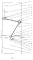
- the cutting system 1 shown schematically in FIG. 1 consists of a supply part 2 and a work table 4.
- a machine portal 5 is located above the work table 4. It runs on a rail 6 and a rack 26 attached next to the work table 4.
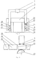
- the machine portal 5 is mounted on the rail 6 with a known ball guide 20 with ball circulation.
- the rail 6 is therefore provided with a V-shaped groove 21, on the side flanks of which the balls 22 of the ball guide 20 run.
- a toothed wheel 24, which drives the machine portal 5, engages in a toothed rack 23 constructed from known toothed rack segments.
- On the other side of the work table 4 there is a toothed rack 26 made up of toothed rack segments 25.
- a toothed wheel 27 attached to the machine portal 5 runs in the toothed rack 26 facing away from the machine portal 5. The toothed wheel 27 drives the machine portal 5 on this side.
- the machine portal 5 carries a carriage 7 on which a cutting head 8 is attached in a height-adjustable manner.
- an intermediate container 9 with a suction pump 10.
- the intermediate container 9 is connected to the cutting head 8 via a hose 11.
- the cutting head 8 carries a water jet nozzle 32 which is surrounded by a protective jacket 31.
- a housing 33 is attached to the protective jacket 31.
- the housing 33 surrounds the water jet nozzle 32 and contains a device for generating a water wall 48 as a protective bell around the cutting jet.
- a two-part coupling arm 13 is fastened to the slide 7 via a joint 12.
- the coupling arm 13 enters between its partial arms Joint 14 and is attached to the supply part 2 via a joint 15.
- a pressure pipeline 16 is located on the coupling arm 13. Spirally wound pipe sections 17 are located above the joints 12, 14 and 15. A slot guide 18 is located on the carriage 7 on the coupling arm 13. The pressure pipeline 16 is guided in the coupling arm 13 so that it can be lifted off.
- the intermediate container 9 is connected to the storage containers 3 via a flexible suction line 19, which is guided inside the coupling arm 13 and is placed around the joint 14.
- a hose (not shown) runs as a supply line for the device for producing a protective bell from service water.
- the hose is connected to a hose extension 38 on the housing 33.
- a stepped central bore 34 in the housing 33 which widens into a bell-shaped recess 35.
- a holding tube 36 encasing the water jet cutting nozzle 32.
- a side bore 37 connects the enlarged part of the central bore 34 with the hose attachment 38.
- the holding tube 36 ends in a collar 39, on which a hemispherical distributor body 40 is rotatably fastened.
- curved ribs 41 are applied on the outer surface of the distributor body 40.
- the bell-shaped recess 35 is shaped such that a space remains as an annular gap 43 between its wall and the outer surface of the distributor body 40.
- the annular gap 43 has a constant cross-sectional area which corresponds to the cross-sectional area of the side bore 37. This guarantees an even distribution of the water forming the protective bell.
- the wall of the housing 33 projects beyond the distributor body 40.
- a slot 44 is located therein.
- An arm 46 engages in the slot 44.
- a sensor 45 is attached to the arm 46 and includes the water jet cutting nozzle 32. Cuttings 47 are scanned with the sensor 45.
- the material to be cut 47 lies on the work table 4 under the water jet cutting nozzle 32.
- the correct cutting distance for the water jet cutting nozzle 32 is determined with the sensor 45.
- the sensor 45 is pulled back into the recess 35.
- water is supplied via the side bore 37.
- An annular water wall 48 is formed around the water jet cutting nozzle 32.
- the water wall 48 encloses a closed cutting space for noise and splash water protection.
- the coupling arm 13 is also moved over the cutting tray 1.
- the spirally wound pipe sections 17 allow movement in the joints 12, 14 and 15 through an angle of 120 °, so that pressurized water can be fed to the cutting head 8 at all times.
- the suction pump 10 creates a vacuum in the suction line 19 and sucks abrasive from one of the storage containers 3 into the intermediate container 9, which regulates the work of the suction pump by means of a fill level control, not shown.
Landscapes
- Engineering & Computer Science (AREA)
- Mechanical Engineering (AREA)
- Life Sciences & Earth Sciences (AREA)
- Forests & Forestry (AREA)
- Perforating, Stamping-Out Or Severing By Means Other Than Cutting (AREA)
Description
- Die Erfindung betrifft eine getrennte Zuführung von Flüssigkeiten, Abrasivmitteln und anderen Versorgungsmitteln zu einem in drei Dimensionen bewegbaren Schneidkopf einer Fluidstrahlschneidanlage.
- Das Schneiden von weichen, elastischen, wärmeempfindlichen, wie auch das von harten und spröden Materialien mit einem Fluidstrahl ist bekannt. Dem Fluidstrahl kann ein Abrasivmittel zugemischt sein. Das Abrasivmittel wird aus einem am Schneidkopf befindlichen und mit einem Schneidkopf bewegten Vorratsbehälter zur Zumischung entnommen. Der Vorratsbehälter enthält den für den Schneidvorgang erforderlichen Vorrat an Abrasivmittel. Nach jedem Schneidvorgang ist der Vorratsbehälter erneut zu füllen oder auszutauschen (Technische Rundschau, Bd. 81, Seite 32).
- Durch das Mitführen des gesamten Vorrats an Abrasivmittel ist die Dauer des Schneidvorganges begrenzt und die Schneidgeschwindigkeit auf Grund der zu beschleunigenden Masse relativ niedrig. Das Fluid wird in einer Hochdruckpumpe neben der Schneidanlage unter hohen Druck gesetzt und über eine Hochdruckleitung dem von einem Portal oder einem Roboterarm geführten Schneidkopf zugeführt. Dazu verbindet ein peitschenartig gebogenes, frei im Raum befindliches Hochdruckrohr über Rohrdrehgelenke den beweglichen Schneidkopf mit dem stationären Druckverstärker. Es ist auch bekannt, das Hochdruckrohr über spiralig gewundene, an dem Druckverstärker und am Schneidkopf gelagerte Rohrstücke zu verbinden. DPS 3 631 116 beschreibt darauf aufbauend die Verwendung eines zwischen einem Ausleger und dem Chassis angebrachten spiralig gewundenen Rohrstücks. Vom Ende des Auslegers wird das Hochdruckrohr im weiten Bogen als freie Leitung zum Schneidkopf geführt. Freie Druckleitungen sind besonders bei mit Kränen bedienten Großanlagen erheblich gefährdet.
- Aus dem US-Patent 3 978 748 ist eine Wasserstrahlschneidmaschine für das reine Wasserstrahlschneiden ohne Abrasivmittel bekannt, bei der die Hochdruckwasserleitung im Innern einer aus zwei gelenkig miteinander verbundenen Armen bestehenden Verbindung zwischen einer stationären Hochdruckpumpe und einem auf einem Portal bewegten Schneidkopf geführt ist. Über die Gelenke in der Verbindung ist die Hochdruckleitung durch zu Torsionsfedern gewundene Rohrstücke geführt. Die Elastizität in Ausrichtung der am Schneidkopf befindlichen Torsionsfeder wird zu einer Bewegung des Schneidkopfes in Z-Richtung benutzt, wobei diese Bewegung erheblich begrenzt ist. Das Portal läuft mit Rollen auf Schienen und wird mit Spindeln angetrieben, die von Schrittmotoren bewegt werden. Bei einer im Innern eines Verbindungsarms geführten Hochdruckleitung ist der Raum für die Torsionsfedern sehr begrenzt. Deshalb ist eine Maßarbeit für die Torsionsfedern und beim Verlegen der Hochdruckleitung erforderlich, da bei der Bewegung des Verbindungsarms die Torsionsfedern gegen die Armwandung gedrückt werden können, was zu einer Zerstörung der Hochdruckleitung durch verstärkte Reibung führen kann.
- Der Erfindung liegt deshalb die Aufgabe zugrunde, über einen Koppelarm die Hochdruckleitung, eine Abrasivmittelleitung und andere Versorgungsleitungen von stationären Versorgungen aus zu einem an einem auf Zahnstangen laufenden Portal befindlichen Schneidkopf zu führen.
- Zur Lösung der Aufgabe ist die Flüssigkeits- und Abrasivmittelzuführung für eine Fluidstrahlschneidanlage durch die Merkmale des Patentanspruchs gekennzeichnet.
- Die Erfindung soll nachstehend an Hand eines Ausführungsbeispiels näher erläutert werden. Die Zeichnung zeigt in
- Fig. 1.:
- einen Blick auf die schematisch dargestellte Schneidanlage
- Fig. 2.:
- ein stilisiertes Maschinenportal
- Fig. 3.:
- einen Ausschnitt der Auflage des Maschinenportals auf der Zahnstange
- Fig. 4.:
- einen Schnitt durch eine Vorrichtung zur Erzeugung einer Schutzglocke
- Fig. 5.:
- einen Verteilerkörper in Draufsicht.
- Die in Fig. 1 schematisch dargestellte Schneidanlage 1 besteht aus einem Versorgungsteil 2 und einem Arbeitstisch 4. Im Versorgungsteil 2 befindet sich Vorratsbehälter 3 für Abrasivmittel. Über dem Arbeitstisch 4 befindet sich ein Maschinenportal 5.Es läuft auf einer neben dem Arbeitstisch 4 angebrachten Schiene 6 und einer Zahnstange 26. Auf der Schiene 6 ist das Maschinenportal 5 mit einer bekannten Kugelführung 20 mit Kugelumlauf gelagert. Die Schiene 6 ist deshalb mit einer V-förmigen Nut 21 versehen, auf deren Seitenflanken die Kugeln 22 der Kugelführung 20 laufen. In eine aus bekannten Zahnstangensegmenten aufgebauten Zahnstange 23 greift ein das Maschinenportal 5 antreibendes Zahnrad 24 ein. Auf der anderen Seite des Arbeitstisches 4 befindet sich eine aus Zahnstangensegmenten 25 aufgebaute Zahnstange 26. In der mit ihren Zähnen vom Maschinenportal 5 abgewandten Zahnstange 26 läuft ein am Maschinenportal 5 angebrachtes Zahnrad 27. Das Zahnrad 27 treibt das Maschinenportal 5 auf dieser Seite an.
- Auf der Rückseite der Zahnstange 26 laufen zwischen dem Maschinenportal 5 und der Zahnstange 26 angebrachte, tonnenförmige Walzen 28. Dazu sind die Rückseiten der Zahnstangensegmente 25 plangeschliffen und gehärtet. An der Stirnseite der Zahnstangensegmente 25 befinden sich die Rückseite der Zahnstangensegmente 25 verlängernde Nasen 30. Beim Montieren der Zahnstange 26 entstehen zwischen den Zahnstangensegmenten 25 Fugen 29, die nur an der Rückseite der Zahnstange 26 durch die Fugen 29 überbrückenden Nasen 30 geschlossen werden.
- Das Maschinenportal 5 trägt einen Schlitten 7, an dem ein Schneidkopf 8 höhenverstellbar angebracht ist. Neben dem Schneidkopf 8 befindet sich ein Zwischenbehälter 9 mit einer Saugpumpe 10. Der Zwischenbehälter 9 ist über eine Schlauchleitung 11 mit dem Schneidkopf 8 verbunden. Der Schneidkopf 8 trägt eine Wasserstrahldüse 32, die von einem Schutzmantel 31 umgeben ist. Am Schutzmantel 31 ist ein Gehäuse 33 angebracht. Das Gehäuse 33 umgibt die Wasserstrahldüse 32 und enthält eine Vorrichtung zur Erzeugung einer Wasserwand 48 als Schutzglocke um den Schneidstrahl. Am Schlitten 7 ist über ein Gelenk 12 ein zweiteiliger Koppelarm 13 befestigt. Der Koppelarm 13 trägt zwischen seinen Teilarmen ein Gelenk 14 und ist über ein Gelenk 15 am Versorgungsteil 2 befestigt. Auf dem Koppelarm 13 befindet sich eine Druckrohrleitung 16. Über den Gelenken 12, 14 und 15 befinden sich spiralig gewundene Rohrstücke 17. Am Schlitten 7 befindet sich auf dem Koppelarm 13 eine Schlitzführung 18. In ihr wird die Druckrohrleitung 16 vom Koppelarm 13 abhebbar geführt. Der Zwischenbehälter 9 ist mit den Vorratsbehältern 3 über eine flexible Saugleitung 19 verbunden, die im Innern des Koppelarmes 13 geführt und um das Gelenk 14 herumgelegt ist. Neben der Saugleitung 19 läuft ein nicht dargestellter Schlauch als Versorgungsleitung für die Vorrichtung zur Erzeugung einer Schutzglocke aus Brauchwasser.
- Der Schlauch ist an einem Schlauchansatz 38 am Gehäuse 33 angeschlossen. Im Gehäuse 33 befindet sich eine abgestufte Zentralbohrung 34, die sich zu einer glockenförmigen Ausnehmung 35 erweitert. In der Zentralbohrung 34 befindet sich ein die Wasserstrahlschneiddüse 32 ummantelndes Halterohr 36. Eine Seitenbohrung 37 verbindet den erweiterten Teil der Zentralbohrung 34 mit dem Schlauchansatz 38. Das Halterohr 36 endet in einem Bund 39, auf dem ein halbkugliger Verteilerkörper 40 drehbar befestigt ist. Auf der Außenfläche des Verteilerkörpers 40 sind von dessen Mittelloch 42 ausgehend, geschwungene Rippen 41 aufgebracht. Die glockenförmige Ausnehmung 35 ist so geformt, daß zwischen ihrer Wand und der Außenfläche des Verteilerkörpers 40 ein Freiraum als Ringspalt 43 bleibt. Der Ringspalt 43 hat trotz wachsendem Durchmesser eine konstante Querschnittfläche, die der Querschnittfläche der Seitenbohrung 37 entspricht. Damit wird eine gleichmäßige Verteilung des die Schutzglocke bildenden Wassers garantiert. Die Wandung des Gehäuses 33 überragt den Verteilerkörper 40. In ihr befindet sich ein Schlitz 44. In dem Schlitz 44 greift ein Arm 46 ein. An dem Arm 46 ist ein Sensor 45 befestigt, der die Wasserstrahlschneiddüse 32 umfaßt. Mit dem Sensor 45 wird Schneidgut 47 abgetastet. Das Schneidgut 47 liegt auf dem Arbeitstisch 4 unter der Wasserstrahlschneiddüse 32. Mit dem Sensor 45 wird der richtige Schneidabstand für die Wasserstrahlschneiddüse 32 ermittelt. Bei Beginn der Schneidarbeiten wird der Sensor 45 in die Ausnehmung 35 zurückgezogen. Gleichzeitig wird Wasser über die Seitenbohrung 37 zugeführt. Dieses wird verwirbelt und dreht den Verteilerkörper 40. Damit wird eine gleichmäßige Wasserverteilung in der Ausnehmung 35 erreicht. Es bildet sich eine ringförmige Wasserwand 48 um die Wasserstrahlschneiddüse 32. Die Wasserwand 48 schließt einen geschlossenen Schneidraum zum Lärm- und Spritzwasserschutz in sich ein.
- Bei der Bewegung des Schlittens 7 und des Maschinenportals 5 wird der Koppelarm 13 über der Schneidablage 1 mit bewegt. Durch die spiralig gewundenen Rohrstücke 17 ist eine Bewegung in den Gelenken 12, 14 und 15 um einen Winkel von 120° möglich, so daß ständig Druckwasser dem Schneidkopf 8 zugeführt werden kann. Die Saugpumpe 10 erzeugt in der Saugleitung 19 ein Vakuum und saugt Abrasivmittel aus einem der Vorratsbehälter 3 in den Zwischenbehälter 9, der durch eine nicht dargestellte Füllstandsreglung die Arbeit der Saugpumpe reguliert.
-
- 1.
- Schneidanlage
- 2.
- Versorgungsteil
- 3.
- Vorratsbehälter
- 4.
- Arbeitstisch
- 5.
- Maschinenportal
- 6.
- Schiene
- 7.
- Schlitten
- 8.
- Schneidkopf
- 9.
- Zwischenbehälter
- 10.
- Saugpumpe
- 11.
- Schlauchleitung
- 12.
- Gelenk
- 13.
- Koppelarm
- 14.
- Gelenk
- 15.
- Gelenk
- 16.
- Druckrohrleitung
- 17.
- Rohrstück
- 18.
- Schlitzführung
- 19.
- Saugleitung
- 20.
- Kugelführung
- 21.
- Nut
- 22.
- Kugel
- 23.
- Zahnstange
- 24.
- Zahnrad
- 25.
- Zahnstangensegment
- 26
- Zahnstange
- 27.
- Zahnrad
- 28.
- Walze
- 29.
- Fuge
- 30.
- Nase
- 31.
- Schutzmantel
- 32.
- Wasserstrahlschneiddüse
- 33.
- Gehäuse
- 34.
- Zentralbohrung
- 35.
- Ausnehmung
- 36.
- Halterohr
- 37.
- Seitenbohrung
- 38.
- Schlauchansatz
- 39.
- Bund
- 40.
- Verteilerkörper
- 41.
- Rippen
- 42.
- Mittelloch
- 43.
- Ringspalt
- 44.
- Schlitz
- 45.
- Sensor
- 46.
- Arm
- 47.
- Schneidgut
- 48.
- Wasserwand
Claims (1)
- Flüssigkeits- und Abrasivmittelzuführung für eine Fluidstrahlschneidanlage (1) mit einem auf einem Maschinenportal (5) laufenden und einen Schneidkopf (8) tragenden Schlitten (7), mit einem am Schneidkopf (8) befestigten Zwischenbehälter (9) für Abrasivmittel, mit einem ortsfesten Versorgungsteil (2) der Schneidanlage (1), in dem sich eine Hochdruckfluid liefernde Hochdruckpumpe befindet, und mit einer vom Versorgungsteil (2) zum Schneidkopf (8) führenden Druckrohrleitung (16), dadurch gekennzeichnet, daß sich im Versorgungsteil ein Vorratsbehälter (3) für Abrasivmittel befindet, daß ein gelenkiger, zweiteiliger Koppelarm (13) vorgesehen ist, der in der Nähe des Vorratsbehälters (3) am Versorgungsteil (2) sowie am Schlitten (7), von diesem bewegbar, gelenkig gelagert ist und den Schlitten (7) mit dem Versorgungsteil (2) verbindet, daß der Koppelarm (13) eine in seinem Innern geführte flexible, um die Gelenke (12, 12, 15) herum geführte, die Vorratsbehälter (3) über den Zwischenbehälter (9) mit einer durch eine Füllstandsregelung regulierten Saugpumpe (10) verbindende Saugleitung (19) und eine neben der Saugleitung (19) liegende Schlauchleitung, die zum Schlauchansatz (38) an einem vom Schneidkopf getragenem, eine Vorrichtung zur Erzeugung einer Wasserwand (48) rings um den Schneidstrahl bergenden Gehäuse (33) führt, aufweist, und daß sich auf dem Koppelarm (13) die mit spiralig gewundenen Rohrstücken (17) über die Gelenke (12, 14, 15) des Koppelarms (13) geführte Druckrohrleitung (16) befindet, wobei das über dem Gelenk (15) am Maschinenportal (5) befindliche Rohrstück (17) am Schneidkopf (8) befestigt und mit diesem vertikal bewegbar und die Rohrleitung (16) dort in einer vom Koppelarm (13) getragenen Schlitzführung (18) geführt vom Koppelarm (13) abhebbar ist, und daß das noch weitere Versorgungsleitungen für den Schneidkopf (8) tragende Maschinenportal (5) neben dem Arbeitstisch (4) auf einer Seite mit einer Kugelführung (20) in einer Schiene (6) geführt und auf der anderen Seite auf der Rückseite einer aus Zahnstangenelementen (25) aufgebauten Zahnstange (23), deren Fugen (29) überbrückt sind, beweglich gelagert ist.
Applications Claiming Priority (6)
| Application Number | Priority Date | Filing Date | Title |
|---|---|---|---|
| DE4235091A DE4235091C2 (de) | 1992-10-17 | 1992-10-17 | Flüssigkeits- und Abrasivmittelzuführung für eine Fluidstrahlschneidanlage |
| DE4235091 | 1992-10-17 | ||
| DE4313347 | 1993-04-23 | ||
| DE19934313347 DE4313347A1 (de) | 1993-04-23 | 1993-04-23 | Schutzglocke für den Schneidstrahl einer Wasserstrahlschneidanlage |
| DE9308023U | 1993-05-27 | ||
| DE9308023U DE9308023U1 (de) | 1993-05-27 | 1993-05-27 | Führung und Antrieb eines Maschinenportals |
Publications (2)
| Publication Number | Publication Date |
|---|---|
| EP0594091A1 EP0594091A1 (de) | 1994-04-27 |
| EP0594091B1 true EP0594091B1 (de) | 1997-06-18 |
Family
ID=27204336
Family Applications (1)
| Application Number | Title | Priority Date | Filing Date |
|---|---|---|---|
| EP93116760A Expired - Lifetime EP0594091B1 (de) | 1992-10-17 | 1993-10-16 | Flüssigkeits- und Abrasivmittelzuführung für eine Fluidstrahlschneidanlage |
Country Status (3)
| Country | Link |
|---|---|
| EP (1) | EP0594091B1 (de) |
| JP (1) | JPH06320426A (de) |
| AT (1) | ATE154538T1 (de) |
Families Citing this family (8)
| Publication number | Priority date | Publication date | Assignee | Title |
|---|---|---|---|---|
| IT1268402B1 (it) * | 1994-10-11 | 1997-02-27 | G M P Poliuretani Srl | Impianto automatico di trattamento superficiale di prodotti |
| DE4440208A1 (de) * | 1994-11-10 | 1996-05-15 | Alba Ind & Umweltschutzservice | Verfahren und Vorrichtung zum Zerschneiden eines Körpers aus festen Explosivstoffen, insbesondere Composite-Raketentreibstoffen |
| GB9803553D0 (en) * | 1998-02-20 | 1998-04-15 | Burgoyne Myles C | Transporting devices |
| ATE320889T1 (de) | 2001-12-06 | 2006-04-15 | Karl-Heinz Schmall | Wasserstrahl-schneidemaschine mit berührungsloser und wahlweise taktiler abstands-führungssensor- einrichtung |
| WO2005057650A1 (en) * | 2003-12-12 | 2005-06-23 | Sunyang Tech Co., Ltd. | A water jet singulation apparatus for semiconductor manufacture and singulation method thereof |
| CN103264353B (zh) * | 2013-05-30 | 2015-09-23 | 南京大地水刀股份有限公司 | 悬臂式筒体封头专用数控水切割机 |
| CN104259996B (zh) * | 2014-09-09 | 2016-06-22 | 苏州华威工程技术有限公司 | 喷砂清洗装置 |
| JP6450791B2 (ja) * | 2017-03-17 | 2019-01-09 | ファナック株式会社 | 工作機械 |
Family Cites Families (2)
| Publication number | Priority date | Publication date | Assignee | Title |
|---|---|---|---|---|
| US3978748A (en) * | 1974-11-25 | 1976-09-07 | Camsco, Inc. | Fluid jet cutting system |
| FR2411069A1 (fr) * | 1977-12-06 | 1979-07-06 | Bertin & Cie | Perfectionnements aux dispositifs de decoupe de materiau en feuille, par jet de fluide |
-
1993
- 1993-10-14 JP JP5256935A patent/JPH06320426A/ja active Pending
- 1993-10-16 AT AT93116760T patent/ATE154538T1/de not_active IP Right Cessation
- 1993-10-16 EP EP93116760A patent/EP0594091B1/de not_active Expired - Lifetime
Also Published As
| Publication number | Publication date |
|---|---|
| EP0594091A1 (de) | 1994-04-27 |
| JPH06320426A (ja) | 1994-11-22 |
| ATE154538T1 (de) | 1997-07-15 |
Similar Documents
| Publication | Publication Date | Title |
|---|---|---|
| DE4235091C2 (de) | Flüssigkeits- und Abrasivmittelzuführung für eine Fluidstrahlschneidanlage | |
| DE2745927A1 (de) | Verbesserungen zu einrichtungen zum belegen von schiffen, insbesondere tankschiffen an offshorebohrungsplattformen | |
| DE69219429T2 (de) | Bodenflächenstrahlgerät | |
| DE2514909C3 (de) | Verfahren und Vorrichtung zum Anschließen einer unterseeischen Zentralstation an Bohrlochköpfe und Förderleitungen | |
| DE2525761A1 (de) | Vorrichtung zum strahlen von grossraeumigen und grossflaechigen werkstuecken | |
| EP3353415B1 (de) | Injektorprüfvorrichtung | |
| DE3113028A1 (de) | Vorrichtung zur oberflaechenbehandlung von unterwasserbauwerken und schiffen | |
| DE3224498C2 (de) | Rohrmolch | |
| EP0594091A1 (de) | Flüssigkeits- und Abrasivmittelzuführung für eine Fluidstrahlschneidanlage | |
| DE3114307C2 (de) | Reinigungsvorrichtung für den Mischraum eines Betonmischers | |
| DE19934241A1 (de) | Vorrichtung zum Durchführen von Kanalarbeiten | |
| DE7722908U1 (de) | Vorrichtung zur automatischen Auftragsschweißung | |
| DE2218756B2 (de) | Vorrichtung zum Aufspritzen von Polyurethanschaum auf die Wandfläche eines Behälters | |
| DE3801003A1 (de) | Vorrichtung zur beschickung von tunnelschalungen mit beton | |
| EP0542212B1 (de) | Vorrichtung zum Reinigen von Rohren | |
| DD224793A1 (de) | Verfahren und vorrichtung fuer den betrieb von gaslaserkoepfen | |
| DE3627556C2 (de) | ||
| EP1523249B1 (de) | Verfahren und vorrichtung zum herstellen von mit kohlendioxid versetztem tafelwasser | |
| DE3590518C2 (de) | ||
| EP0151773B1 (de) | Applikationsgerät für Unterwasser-Anstrichstoffe | |
| DE9307758U1 (de) | Tieflochbohrmaschine | |
| DE10053891A1 (de) | Vorrichtung zum Entfernen von Rohrinnenbeschichtungen und/oder zur Strahlentrostung von Rohrinnenflächen in Rohrleitungen | |
| DD141846A1 (de) | Geraet zum aufschmelzen und verteilen von heissbitumen | |
| DE29818039U1 (de) | Elektronisch gesteuerte Universal-Wasserstrahlschneidanlage | |
| DE671720C (de) | Verfahren zum Rostschutz von Gasbehaelterinnenflaechen |
Legal Events
| Date | Code | Title | Description |
|---|---|---|---|
| PUAI | Public reference made under article 153(3) epc to a published international application that has entered the european phase |
Free format text: ORIGINAL CODE: 0009012 |
|
| AK | Designated contracting states |
Kind code of ref document: A1 Designated state(s): AT CH FR GB IT LI SE |
|
| 17P | Request for examination filed |
Effective date: 19941025 |
|
| 17Q | First examination report despatched |
Effective date: 19960212 |
|
| GRAG | Despatch of communication of intention to grant |
Free format text: ORIGINAL CODE: EPIDOS AGRA |
|
| GRAH | Despatch of communication of intention to grant a patent |
Free format text: ORIGINAL CODE: EPIDOS IGRA |
|
| ITF | It: translation for a ep patent filed | ||
| GRAH | Despatch of communication of intention to grant a patent |
Free format text: ORIGINAL CODE: EPIDOS IGRA |
|
| GRAA | (expected) grant |
Free format text: ORIGINAL CODE: 0009210 |
|
| AK | Designated contracting states |
Kind code of ref document: B1 Designated state(s): AT CH FR GB IT LI SE |
|
| PG25 | Lapsed in a contracting state [announced via postgrant information from national office to epo] |
Ref country code: GB Effective date: 19970618 |
|
| REF | Corresponds to: |
Ref document number: 154538 Country of ref document: AT Date of ref document: 19970715 Kind code of ref document: T |
|
| REG | Reference to a national code |
Ref country code: CH Ref legal event code: NV Representative=s name: BOVARD AG PATENTANWAELTE Ref country code: CH Ref legal event code: EP |
|
| ET | Fr: translation filed | ||
| GBV | Gb: ep patent (uk) treated as always having been void in accordance with gb section 77(7)/1977 [no translation filed] |
Effective date: 19970618 |
|
| PLBE | No opposition filed within time limit |
Free format text: ORIGINAL CODE: 0009261 |
|
| STAA | Information on the status of an ep patent application or granted ep patent |
Free format text: STATUS: NO OPPOSITION FILED WITHIN TIME LIMIT |
|
| 26N | No opposition filed | ||
| PGFP | Annual fee paid to national office [announced via postgrant information from national office to epo] |
Ref country code: FR Payment date: 19990907 Year of fee payment: 7 |
|
| PGFP | Annual fee paid to national office [announced via postgrant information from national office to epo] |
Ref country code: AT Payment date: 19991005 Year of fee payment: 7 |
|
| PGFP | Annual fee paid to national office [announced via postgrant information from national office to epo] |
Ref country code: CH Payment date: 19991021 Year of fee payment: 7 |
|
| PGFP | Annual fee paid to national office [announced via postgrant information from national office to epo] |
Ref country code: SE Payment date: 19991027 Year of fee payment: 7 |
|
| PG25 | Lapsed in a contracting state [announced via postgrant information from national office to epo] |
Ref country code: AT Free format text: LAPSE BECAUSE OF NON-PAYMENT OF DUE FEES Effective date: 20001016 |
|
| PG25 | Lapsed in a contracting state [announced via postgrant information from national office to epo] |
Ref country code: SE Free format text: THE PATENT HAS BEEN ANNULLED BY A DECISION OF A NATIONAL AUTHORITY Effective date: 20001030 |
|
| PG25 | Lapsed in a contracting state [announced via postgrant information from national office to epo] |
Ref country code: LI Free format text: LAPSE BECAUSE OF NON-PAYMENT OF DUE FEES Effective date: 20001031 Ref country code: CH Free format text: LAPSE BECAUSE OF NON-PAYMENT OF DUE FEES Effective date: 20001031 |
|
| REG | Reference to a national code |
Ref country code: CH Ref legal event code: PL |
|
| EUG | Se: european patent has lapsed |
Ref document number: 93116760.5 |
|
| PG25 | Lapsed in a contracting state [announced via postgrant information from national office to epo] |
Ref country code: FR Free format text: LAPSE BECAUSE OF NON-PAYMENT OF DUE FEES Effective date: 20010629 |
|
| REG | Reference to a national code |
Ref country code: FR Ref legal event code: ST |
|
| PG25 | Lapsed in a contracting state [announced via postgrant information from national office to epo] |
Ref country code: IT Free format text: LAPSE BECAUSE OF NON-PAYMENT OF DUE FEES;WARNING: LAPSES OF ITALIAN PATENTS WITH EFFECTIVE DATE BEFORE 2007 MAY HAVE OCCURRED AT ANY TIME BEFORE 2007. THE CORRECT EFFECTIVE DATE MAY BE DIFFERENT FROM THE ONE RECORDED. Effective date: 20051016 |