EP0592818A2 - Device for storing and taking out blanks - Google Patents
Device for storing and taking out blanks Download PDFInfo
- Publication number
- EP0592818A2 EP0592818A2 EP93114680A EP93114680A EP0592818A2 EP 0592818 A2 EP0592818 A2 EP 0592818A2 EP 93114680 A EP93114680 A EP 93114680A EP 93114680 A EP93114680 A EP 93114680A EP 0592818 A2 EP0592818 A2 EP 0592818A2
- Authority
- EP
- European Patent Office
- Prior art keywords
- blank
- blanks
- sun gear
- planet gears
- holding
- Prior art date
- Legal status (The legal status is an assumption and is not a legal conclusion. Google has not performed a legal analysis and makes no representation as to the accuracy of the status listed.)
- Granted
Links
Images


Classifications
-
- B—PERFORMING OPERATIONS; TRANSPORTING
- B65—CONVEYING; PACKING; STORING; HANDLING THIN OR FILAMENTARY MATERIAL
- B65H—HANDLING THIN OR FILAMENTARY MATERIAL, e.g. SHEETS, WEBS, CABLES
- B65H3/00—Separating articles from piles
- B65H3/08—Separating articles from piles using pneumatic force
- B65H3/10—Suction rollers
-
- B—PERFORMING OPERATIONS; TRANSPORTING
- B65—CONVEYING; PACKING; STORING; HANDLING THIN OR FILAMENTARY MATERIAL
- B65H—HANDLING THIN OR FILAMENTARY MATERIAL, e.g. SHEETS, WEBS, CABLES
- B65H2301/00—Handling processes for sheets or webs
- B65H2301/40—Type of handling process
- B65H2301/42—Piling, depiling, handling piles
- B65H2301/423—Depiling; Separating articles from a pile
- B65H2301/4232—Depiling; Separating articles from a pile of horizontal or inclined articles, i.e. wherein articles support fully or in part the mass of other articles in the piles
- B65H2301/42322—Depiling; Separating articles from a pile of horizontal or inclined articles, i.e. wherein articles support fully or in part the mass of other articles in the piles from bottom of the pile
-
- B—PERFORMING OPERATIONS; TRANSPORTING
- B65—CONVEYING; PACKING; STORING; HANDLING THIN OR FILAMENTARY MATERIAL
- B65H—HANDLING THIN OR FILAMENTARY MATERIAL, e.g. SHEETS, WEBS, CABLES
- B65H2701/00—Handled material; Storage means
- B65H2701/10—Handled articles or webs
- B65H2701/17—Nature of material
- B65H2701/176—Cardboard
- B65H2701/1764—Cut-out, single-layer, e.g. flat blanks for boxes
Definitions
- the invention relates to a device for storing a supply of blanks from thin cardboard for hinged boxes (hinge-lid packs) and for removing individual blanks, a stack of blanks being accommodated in a blank magazine with a lower removal opening and lateral conveying elements converging downwards , such that the lower blanks of the stack of blanks are kept ready in a concavely curved position and are removed by a removal member with a plurality of rotatable planet gears and a sun gear cooperating therewith and are removed by the sun gear.
- Such a device is known from DE-24 36 354.
- the fixed, rotatable sun gear are in this embodiment assigned two opposing planet gears. With their circumferential surface, these each capture the lower blank of the blank stack.
- suction bores are arranged on the circumference of the planet gears. The blank resting on the outer surface of the planetary gear is transferred to the circumference of the sun gear during the further rolling movement and is fed by this to a removal path.
- the lateral conveying elements which delimit the blank magazine in the lower region are designed as downwardly converging conveyor belts. These capture the blanks in the region of their narrow end edges in the central region thereof, that is to say on the edges of a front wall on the one hand and an inner flap of the blank on the other hand.
- the planet gears - and correspondingly the sun gear - are designed as two suction disks which are arranged at a distance from one another and which only grasp the cut in the region of lateral folding tabs. Since the side folding flaps are separated from one another by a number of longitudinal and transverse separating cuts in a conventional cut for hinge-lid packs, it is difficult to hold and transport the cuts sufficiently on curved or cylindrical contact surfaces. For this reason, the known device has not proven itself in practice.
- the invention has for its object to develop and improve the above-described device in such a way that the blanks experience a more precise and trouble-free guidance during removal from the blank magazine and during further transport, taking into account the special design of the side folding flaps .
- the device according to the invention is characterized in that the planet gears with their circumferential surfaces each capture a blank only in a central contact area between the side folding tabs, namely in the area of a blank center strip.
- the sun gear and a further discharge element effective according to the invention are also placed on the blanks exclusively in the region of the blank center strip without contact with the side folding tabs. This results in a trouble-free transport of the blanks, since the lateral folding tabs are not caught by the conveying elements.
- the conveying elements of the blank magazine which converge downwards, also capture the blanks only in the region of the blank center strip at end edges.
- the planet gears are designed in the device according to the invention so that a collision with the conveying elements, in particular with lateral support belts, is avoided during the movement to remove a blank from the blank magazine.
- the planet gears are provided with radial depressions between the holding areas that grip the blanks.
- the embodiment shown in the drawings deals with the handling of blanks 10 made of thin cardboard, specifically those for the production of hinged boxes or hinge-lid packs for holding cigarettes.
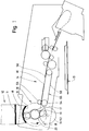
- a stock of such blanks namely a blank stack 11, is accommodated in an upright blank magazine 12. This is provided with a removal opening 13 on the underside.
- the respective lower blank 10 of the blank stack 11 is removed from the blank magazine 12 via the removal opening 13 and fed to the packaging machine via a blank web 14.
- the blank web 14, which is inclined downwards in the conveying direction is located above a plate-shaped folding turret 15 with a vertical axis of rotation.
- the blanks 10 are fed one after the other into pockets of this folding turret.
- a removal unit 16 is used to remove the blanks 10 from the blank magazine 12.
- This consists of a fixed, rotatably mounted central sun wheel 17 and several - in the present embodiment two - planet gears 18, 19. These rotate at a constant speed around the sun gear 17 and additionally about its own axis.
- the diametrically opposed planet gears 18, 19 are arranged on a carrier rotating coaxially with the sun gear 17, namely on a rotor 20.
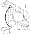
- the blanks 10 stacked with an exact relative position are brought into a concavely curved shape in the region of a lower removal section 21 by exerting pressure on end edges, with the radius of curvature decreasing downwards.
- the arrangement is such that the respective lower blanks 10 are (approximately) deformed in a circular arc in accordance with an outer envelope curve, that is to say in accordance with an outer movement path of the planet gears 18, 19.
- the blanks 10 are moved downward in the region of the removal section 21 by conveying elements converging downwards, namely by means of support belts 22, 23.
- Their mutually facing conveying strands 24, 25 serve to support end edges 26, 27 of the blanks 10.
- the support belts 22, 23 are driven in the sense of a downward conveying movement, preferably at a speed which is approximately 10% above the conveying movement of the blank stack 11 directed towards the removal opening 13.
- the support belts 22, 23 are designed as toothed belts and are guided and driven by deflection rollers 28, 29.
- the inclination of the conveyor strands 24, 25 is approximately 6 ° to the vertical.
- a separate support member for the blanks 10 is arranged directly in the region of the removal opening 13, namely fixed lugs 30, 31. These form a support surface for the end edges 26 and 27 of the blanks 10.
- the planet gears are moved by a corresponding rotary drive of the rotor 20 about a central axis of rotation 32 of the sun gear 17. At the same time rotate the planet gears 18, 19 about their own axis.
- the relative movements are coordinated with one another in such a way that holding members for the blanks 10 arranged on the circumference of the planet gears 18, 19 - in the present exemplary embodiment suction cups 33 or suction bores - each capture a blank 10 at the end region thereof, namely adjacent to the edge edge 26.
- the drive is so designed that the rotor 20 rotates counterclockwise with the planet gears 18, 19.
- the planet gears 18, 19 themselves turn clockwise.
- the blank 10 gripped by the planet gear 18 is applied to the circumference of the planet gear 18 as the rotor 20 rotates further as a result of its independent rotation.
- the end of the blank first detected (adjacent to the edge 26) finally reaches the periphery of the sun wheel 17 and is also grasped by this by holding members, namely suction cups 34. Simultaneous venting of the suction cups 33 of the planetary gear 18 causes the blank 10 to be gradually taken over by the sun gear 17.
- FIG. 5 shows an S-shaped Formation of the blank 10 during a phase of transfer from a planet gear 18, 19 to the periphery of the sun gear 17.
- parts of folding tabs in particular the corner tabs 41, 42, are directed tangentially.
- the effective organs of the blank magazine 12 and of the removal unit 16 act only on the blank 10 in a central area, at least not in the area of the side folding flaps 39..42.
- a central cut strip 46 is indicated by hatching. This forms the contact area of the organs of the blank magazine 12 and the removal unit 16 and ends on both sides at a distance from the side folding tabs.
- the planet gears 18, 19 are designed in a special way to avoid a collision with the support bands 22, 23 and the lugs 30, 31 when blanks 10 are removed from the blank magazine 12.
- trough-shaped depressions 47 are formed along the circumference of the planet gears 18, 19. These extend in the axis-parallel direction and at a distance from one another in the circumferential direction.
- the depressions 47 are arranged such that the lower end of the removal section 21, namely the deflection rollers 29 with the support belts 22, 23 and the lugs 30, 31, each enter a depression 47 when a planet gear 18, 19 is moved past.
- the depressions 47 delimit holding sections 48 on the circumference of the planet gears 18, 19.
- Suction cups 33 are arranged in the region of these holding sections 48, preferably several each lying side by side in the axial direction of the planet wheel 18, 19 and possibly in the circumferential direction. Instead of the above suction cup 33, suction holes can also be provided here.
- the holding section 48 is curved in a cylindrical manner, corresponding to the outer circumference of the planet gear 18, 19.
- each is Planetary gear 18, 19 provided with three holding sections 48 which are arranged along the circumference at equal distances from one another. In the middle there are support webs 49, which also have a cylindrical outer surface and lie with this on the circumference of the planet gear 18, 19.
- the support webs 49 are here without holding or suction members.
- a depression 47 accordingly lies between a holding section 48 and a supporting web 49. The blank 10 received by a planet gear 18, 19 bears against the outer surface of the holding sections 48 and the supporting webs 49.
- the cylindrical sun gear 17 is provided with a plurality of holding areas 50 which are arranged at equal intervals along the circumference. These are each equipped with a plurality of suction cups 34 or suction bores - distributed in the axial direction - for gripping the blank 10.
- the blanks 10 conveyed in the circumferential direction by the sun gear 17 are transported into the blank path 14 on the (lower) side opposite the blank magazine 12.
- a separate removal member cooperates with the sun gear 17.
- the transport disks 51, 52 are driven in the conveying direction.
- the blank 10 is accordingly conveyed between the circumference of the sun wheel 17 and the transport disks 51, 52 into the blank path 14.
- the blank 10 is first grasped by conveyor rollers 53, 54 and moved on.
- an endless conveyor connects to the conveyor rollers 53, 54 according to the exemplary embodiment in FIG. 1, namely a conveyor belt 55 which defines the distances and the subsequent conveying speed the blanks 10 determined.
- the conveyor belt 55 is provided with drivers 56, each of which grips a blank 10 on the rear.
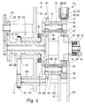
- the removal unit 16 is attached to a part of a machine frame, namely to an (upright) support wall 57.
- the disk-shaped rotor 20 is rotatably mounted with a hollow shaft 58 in a bearing 59 of the support wall 57.
- a drive shaft 60 for the sun gear 17 runs in the hollow shaft 58.
- the planet gears 18, 19 are rotatably mounted on axially parallel support pins 61, 62 which are attached to the rotor 20 so as to protrude on one side.
- a central drive wheel 63 is driven by a motor, not shown.
- the drive wheel consists of two individual wheels 64, 65 (gear wheels) with different diameters.
- the single wheel 64 transmits rotary movements to the drive shaft 60.
- the single wheel 65 is in drive connection with the hollow shaft 58.
- the rotation of the planet gears 18, 19 about its own axis is caused by the drive shaft 60 of the sun gear 17.
- a gear 66 arranged on the drive shaft 60 is in engagement with counter gears 67, 68, which are each assigned to a planet gear 18, 19.
- the transport disks 51, 52 are mounted on a common shaft 69. This is driven by the hollow shaft 58 through a toothed wheel 70 in connection with a further toothed wheel 71 on the shaft 69. The drive is transmitted between them by a toothed belt 72.
- the free side of the removal unit 16 is supported in a fixed pivot bearing 73, specifically via a support pin 74 on the free side of the sun gear 17.
- the dimensions are chosen so that the axial width of the sun gear 17 or the circumferential surface corresponds approximately to the width of the center strip 46.
- the planet gears 18, 19, which are designed with a significantly smaller width, are centered on the sun gear 17 and also on the blank magazine 12.
- the transport disks 51, 52 are arranged at such a distance from one another that a planet gear 18, 19 is located between the transport disks 51, 52 Rotational movement can be temporarily recorded. So that a cylindrical support sleeve 75 of the planet gears 18, 19 can be moved past the inner transport disk 51 without contact during the rotary movements, it is provided with a recess 76 on one side. The size and shape of this recess 76 do justice to the movement sequence of the planet gears 18, 19 and the support sleeve 75.
- the maximum distance between the transport disks 51, 52 is likewise not greater than the width of the central cut-out strip 46.
- the support bands 22, 23 of the blank magazine and the lugs 30, 31 are also of a width and are arranged in such a way that they become effective only in the region of the blank center strip 46.
- the dimensions of the support bands correspond to the width of the planet gears 18, 19.
- suction cups 33, 34 are supplied with negative pressure in a manner known per se.
- a suction line 78 for suction bores or suction cups 33 of the planet gears 18, 19 leads from a fixed channel ring 79 via the support sleeve 75 rotating with the planet gear 18, 19 to the peripheral surface of the planet gear 18, 19.
- the suckers 34 of the sun gear 17 are supplied by a likewise fixed channel ring 80, which is arranged in the region of the fixed pivot bearing 73. From this leads a suction line 81 within the sun gear 17 its peripheral surface.
Abstract
Description
Die Erfindung betrifft eine Vorrichtung zum Speichern eines Vorrats an Zuschnitten aus dünnem Karton für Klappschachteln (Hinge-Lid-Packungen) sowie zur Entnahme einzelner Zuschnitte, wobei ein Zuschnitt-Stapel in einem Zuschnitt-Magazin mit unterer Entnahmeöffnung und nach unten konvergierenden seitlichen Förderorganen Aufnahme findet, derart, daß die unteren Zuschnitte des Zuschnitt-Stapels in einer konkav gewölbten Stellung bereitgehalten und durch ein Entnahmeorgan mit mehreren drehbaren Planetenrädern und einem mit diesen zusammenarbeitenden Sonnenrad entnommen sowie durch das Sonnenrad abtransportiert werden.The invention relates to a device for storing a supply of blanks from thin cardboard for hinged boxes (hinge-lid packs) and for removing individual blanks, a stack of blanks being accommodated in a blank magazine with a lower removal opening and lateral conveying elements converging downwards , such that the lower blanks of the stack of blanks are kept ready in a concavely curved position and are removed by a removal member with a plurality of rotatable planet gears and a sun gear cooperating therewith and are removed by the sun gear.
Eine derartige Vorrichtung ist bekannt durch DE-24 36 354. Dem ortsfesten, drehbaren Sonnenrad sind bei dieser Ausführung zwei einander gegenüberliegende Planetenräder zugeordnet. Diese erfassen mit ihrer Umfangsfläche jeweils den unteren Zuschnitt des Zuschnitt-Stapels. Am Umfang der Planetenräder sind zu diesem Zweck Saugbohrungen angeordnet. Der an der Mantelfläche des Planetenrades anliegende Zuschnitt wird bei der weiteren Abrollbewegung an den Umfang des Sonnenrades übergeben und von diesem einer Abförderbahn zugeführt.Such a device is known from DE-24 36 354. The fixed, rotatable sun gear are in this embodiment assigned two opposing planet gears. With their circumferential surface, these each capture the lower blank of the blank stack. For this purpose, suction bores are arranged on the circumference of the planet gears. The blank resting on the outer surface of the planetary gear is transferred to the circumference of the sun gear during the further rolling movement and is fed by this to a removal path.
Die das Zuschnitt-Magazin im unteren Bereich begrenzenden seitlichen Förderorgane sind bei einem Ausführungsbeispiel dieser bekannten Vorrichtung als nach unten konvergierende Förderbänder ausgebildet. Diese erfassen die Zuschnitte im Bereich ihrer schmalen Endkanten im mittleren Bereich derselben, also an Kanten einer Vorderwand einerseits und eines Deckelinnenlappens des Zuschnitts andererseits. Die Planetenräder - und entsprechend das Sonnenrad - sind als zwei im Abstand voneinander angeordnete Saugscheiben ausgebildet, die den Zuschnitt jeweils nur im Bereich von seitlichen Faltlappen erfassen. Da bei einem üblichen Zuschnitt für Hinge-Lid-Packungen die seitlichen Faltlappen durch mehrere längs- und querverlaufende Trennschnitte voneinander abgeteilt sind, ist es schwierig, die Zuschnitte ausreichend an gewölbten bzw. zylindrischen Anlageflächen zu halten und zu transportieren. Aus diesem Grunde hat sich die bekannte Vorrichtung in der Praxis nicht bewährt.In one embodiment of this known device, the lateral conveying elements which delimit the blank magazine in the lower region are designed as downwardly converging conveyor belts. These capture the blanks in the region of their narrow end edges in the central region thereof, that is to say on the edges of a front wall on the one hand and an inner flap of the blank on the other hand. The planet gears - and correspondingly the sun gear - are designed as two suction disks which are arranged at a distance from one another and which only grasp the cut in the region of lateral folding tabs. Since the side folding flaps are separated from one another by a number of longitudinal and transverse separating cuts in a conventional cut for hinge-lid packs, it is difficult to hold and transport the cuts sufficiently on curved or cylindrical contact surfaces. For this reason, the known device has not proven itself in practice.
Der Erfindung liegt die Aufgabe zugrunde, die eingangs erläuterte Vorrichtung dahingehend weiterzuentwickeln und zu verbessern, daß die Zuschnitte bei der Entnahme aus dem Zuschnitt-Magazin durch die Planetenräder sowie während des weiteren Transports eine exaktere und störungsfreie Führung erfahren unter Berücksichtigung der besonderen Gestaltung der seitlichen Faltlappen.The invention has for its object to develop and improve the above-described device in such a way that the blanks experience a more precise and trouble-free guidance during removal from the blank magazine and during further transport, taking into account the special design of the side folding flaps .
Zur Lösung dieser Aufgabe ist die erfindungsgemäße Vorrichtung dadurch gekennzeichnet, daß die Planetenräder mit ihren Umfangsflächen einen Zuschnitt jeweils ausschließlich in einem mittleren Anlagebereich zwischen den seitlichen Faltlappen erfassen, nämlich im Bereich eines Zuschnitt-Mittelstreifens.To achieve this object, the device according to the invention is characterized in that the planet gears with their circumferential surfaces each capture a blank only in a central contact area between the side folding tabs, namely in the area of a blank center strip.
Auch das Sonnenrad und ein weiteres erfindungsgemäß wirksames Abförderorgan, nämlich ein Abförderrad, erhalten Anlage an den Zuschnitten ausschließlich im Bereich des Zuschnitt-Mittelstreifens ohne Kontakt mit den seitlichen Faltlappen. Hierdurch wird ein störungsfreier Transport der Zuschnitte bewirkt, da die seitlichen Faltlappen durch die Förderorgane nicht erfaßt werden. Auch die nach unten konvergierenden Förderorgane des Zuschnitt-Magazins erfassen die Zuschnitte lediglich im Bereich des Zuschnitt-Mittelstreifens an Endkanten.The sun gear and a further discharge element effective according to the invention, namely a discharge wheel, are also placed on the blanks exclusively in the region of the blank center strip without contact with the side folding tabs. This results in a trouble-free transport of the blanks, since the lateral folding tabs are not caught by the conveying elements. The conveying elements of the blank magazine, which converge downwards, also capture the blanks only in the region of the blank center strip at end edges.
Die Planetenräder sind bei der erfindungsgemäßen Vorrichtung so gestaltet, daß bei der Bewegung zur Entnahme eines Zuschnitts aus dem Zuschnitt-Magazin eine Kollision mit den Förderorganen, insbesondere mit seitlichen Stützbändern, vermieden ist. Die Planetenräder sind zu diesem Zweck mit radialen Vertiefungen zwischen die Zuschnitte erfassenden Haltebereichen versehen.The planet gears are designed in the device according to the invention so that a collision with the conveying elements, in particular with lateral support belts, is avoided during the movement to remove a blank from the blank magazine. For this purpose, the planet gears are provided with radial depressions between the holding areas that grip the blanks.
Weitere Merkmale der Erfindung betreffen die Ausbildung des Getriebes für den Bewegungsablauf des Sonnenrades, der Planetenräder und der Förderscheibe.Further features of the invention relate to the design of the transmission for the movement sequence of the sun gear, the planet gears and the conveyor disk.
Ein Ausführungsbeispiel der erfindungsgemäßen Vorrichtung wird nachfolgend anhand der Zeichnungen näher erläutert. Es zeigt:
- Fig. 1
- ein Zuschnitt-Magazin mit Entnahmevorrichtung für die Zuschnitte und einen Teil einer Verpackungsmaschine in schematischer Seitenansicht,
- Fig. 2
- einen unteren Teil des Zuschnitt-Magazins mit Entnahmevorrichtung in vergrößertem Maßstab, ebenfalls in Seitenansicht,
- Fig. 3
- Sonnenrad und Planetenräder als Teil der Entnahmevorrichtung in nochmals vergrößertem Maßstab, ebenfalls in Seitenansicht,
- Fig. 4
- einen Vertikalschnitt durch die Entnahmevorrichtung einschließlich Getriebe,
- Fig. 5
- einen Zuschnitt für Klappschachteln in ausgebreiteter Stellung,
- Fig. 6
- eine schematisierte Darstellung der Übergabe eines Zuschnitts gemäß Fig. 5 von einem Planetenrad an das Sonnenrad.
- Fig. 1
- a blank magazine with removal device for the blanks and part of a packaging machine in a schematic side view,
- Fig. 2
- a lower part of the blank magazine with removal device on an enlarged scale, also in side view,
- Fig. 3
- Sun gear and planet gears as part of the removal device on a further enlarged scale, also in side view,
- Fig. 4
- a vertical section through the removal device including gear,
- Fig. 5
- a blank for hinged boxes in the spread position,
- Fig. 6
- a schematic representation of the transfer of a blank according to FIG. 5 from a planet gear to the sun gear.
Das in den Zeichnungen dargestellte Ausführungsbeispiel befaßt sich mit der Handhabung von Zuschnitten 10 aus dünnem Karton, und zwar konkret solchen für die Herstellung von Klappschachteln bzw. Hinge-Lid-Packungen zur Aufnahme von Zigaretten. Ein Vorrat an solchen Zuschnitten, nämlich ein Zuschnitt-Stapel 11, findet Aufnahme in einem aufrechten Zuschnitt-Magazin 12. Dieses ist an der Unterseite mit einer Entnahmeöffnung 13 versehen. Der jeweils untere Zuschnitt 10 des Zuschnitt-Stapels 11 wird über die Entnahmeöffnung 13 dem Zuschnitt-Magazin 12 entnommen und über eine Zuschnitt-Bahn 14 der Verpackungsmaschine zugeführt. Bei dem vorliegenden Ausführungsbeispiel gemäß Fig. 1 befindet sich die in Förderrichtung abwärts geneigte Zuschnitt-Bahn 14 oberhalb eines tellerförmigen Faltrevolvers 15 mit vertikaler Drehachse. Die Zuschnitte 10 werden nacheinander in Taschen dieses Faltrevolvers eingefördert.The embodiment shown in the drawings deals with the handling of
Zur Entnahme der Zuschnitte 10 aus dem Zuschnitt-Magazin 12 dient ein Entnahmeaggregat 16. Dieses besteht aus einem ortsfest drehbar gelagerten, also zentralen Sonnenrad 17 und mehreren - bei dem vorliegenden Ausführungsbeispiel zwei - Planetenrädern 18, 19. Diese drehen mit kontinuierlicher Geschwindigkeit um das Sonnenrad 17 und zusätzlich um die eigene Achse. Die einander diametral gegenüberliegenden Planetenräder 18, 19 sind an einem gleichachsig mit dem Sonnenrad 17 drehenden Träger angeordnet, nämlich an einem Rotor 20.To remove the
Die mit exakter Relativstellung gestapelten Zuschnitte 10 werden im Bereich eines unteren Entnahmeabschitts 21 durch Ausübung von Druck auf Endkanten in eine konkav gewölbte Form gebracht mit nach unten abnehmendem Wölbungsradius. Die Anordnung ist so getroffen, daß die jeweils unteren Zuschnitte 10 entsprechend einer äußeren Hüllkurve, also entsprechend einer äußeren Bewegungsbahn der Planetenräder 18, 19, (annähernd) kreisbogenförmig verformt sind.The
Die Zuschnitte 10 werden zu diesem Zweck im Bereich des Entnahmeabschnitts 21 durch nach unten konvergierende Förderorgane abwärtsbewegt, nämlich durch Stützbänder 22, 23. Deren einander zugekehrte Fördertrume 24, 25 dienen zur Abstützung von Endkanten 26, 27 der Zuschnitte 10. Die Stützbänder 22, 23 werden im Sinne einer nach unten gerichteten Förderbewegung angetrieben, und zwar vorzugsweise mit einer Geschwindigkeit, die um etwa 10% über der zur Entnahmeöffnung 13 gerichteten Förderbewegung des Zuschnitt-Stapels 11 liegt. Die Stützbänder 22, 23 sind als Zahnriemen ausgebildet und durch Umlenkwalzen 28, 29 geführt sowie angetrieben. Die Neigung der Fördertrume 24, 25 beträgt etwa 6° zur Senkrechten.For this purpose, the
Unmittelbar im Bereich der Entnahmeöffnung 13 ist ein gesondertes Stützorgan für die Zuschnitte 10 angeordnet, nämlich feststehende Nasen 30, 31. Diese bilden eine Stützfläche für die Endkanten 26 und 27 der Zuschnitte 10.A separate support member for the
Für die Entnahme von Zuschnitten 10 werden die Planetenräder durch entsprechenden Drehantrieb des Rotors 20 um eine zentrale Drehachse 32 des Sonnenrades 17 bewegt. Zugleich drehen die Planetenräder 18, 19 um die eigene Achse. Die Relativbewegungen sind so aufeinander abgestimmt, daß am Umfang der Planetenräder 18, 19 angeordnete Halteorgane für die Zuschnitte 10 - beim vorliegenden Ausführungsbeispiel Sauger 33 bzw. Saugbohrungen - jeweils einen Zuschnitt 10 am Endbereich desselben erfasssen, nämlich benachbart zur Randkante 26. Der Antrieb ist so gestaltet, daß der Rotor 20 mit den Planetenrädern 18, 19 im Gegenuhrzeigersinn umläuft. Die Planetenräder 18, 19 selbst drehen im Uhrzeigersinn.For the removal of
Der von dem Planetenrad 18 erfaßte Zuschnitt 10 wird bei weiterer Drehbewegung des Rotors 20 an den Umfang des Planetenrads 18 infolge der eigenständigen Drehung desselben angelegt. Das zuerst erfaßte Ende des Zuschnitts (benachbart zur Randkante 26) gelangt schließlich an den Umfang des Sonnenrades 17 und wird von diesem ebenfalls durch Halteorgane, nämlich Sauger 34, erfaßt. Eine gleichzeitige Entlüftung der Sauger 33 des Planetenrades 18 bewirkt, daß nunmehr der Zuschnitt 10 nach und nach vom Sonnenrad 17 übernommen wird.The blank 10 gripped by the
Die hier gezeigten Zuschnitte 10 für Klappschachteln bzw. Hinge-Lid-Packungen haben einen charakteristischen Aufbau, der sich aus Fig. 5 ergibt. Ein mittlerer Zuschnitt-Teil wird im wesentlichen durch eine Vorderwand 35, eine anschließende Bodenwand 36 und eine Rückwand 37 gebildet. Hieran schließen entsprechende Zuschnitt-Teile eines Deckels 38 an. Seitliche Bereiche des Zuschnitts 10 bestehen aus Faltlappen, nämlich zu beiden Seiten des mittleren Teils angeordnete Seitenlappen 39 und 40 sowie Ecklappen 40, 41. Diese zu einem standardmäßigen Zuschnitt 10 gehörenden Faltlappen sind durch quergerichtete Trennschnitte 43 sowie durch Längsschnitte 44 und durch Schrägschnitte 45 unterteilt. Diese unterschiedlich gerichteten Schnitte führen zu einem problematischen Verhalten der Faltlappen 39..42, wenn der Zuschnitt 10 in eine bogenförmige Form gebracht wird. Fig. 6 zeigt eine S-förmige Formation des Zuschnitts 10 während einer Phase der Übergabe von einem Planetenrad 18, 19 an den Umfang des Sonnenrades 17. Wie ersichtlich sind Teile von Faltlappen, insbesondere die Ecklappen 41, 42, tangential gerichtet.The
Um die dadurch bedingte Gefahr von Beeinträchtigungen der Zuschnitte 10 zu vermeiden, greifen die wirksamen Organe des Zuschnitt-Magazins 12 und des Entnahmeaggregats 16 ausschließlich in einem mittleren Bereich am Zuschnitt 10 an, jedenfalls nicht im Bereich der seitlichen Faltlappen 39..42. In Fig. 5 ist ein Zuschnitt-Mittelstreifen 46 durch Schraffur gekennzeichnet. Dieser bildet den Anlagebereich der Organe von Zuschnitt-Magazin 12 und Entnahmeaggregat 16 und endet zu beiden Seiten mit Abstand von den seitlichen Faltlappen.In order to avoid the resulting risk of impairment of the
Die Planetenräder 18, 19 sind in besonderer Weise ausgebildet, um bei der Entnahme von Zuschnitten 10 aus dem Zuschnitt-Magazin 12 eine Kollision mit den Stützbändern 22, 23 und den Nasen 30, 31 zu vermeiden. Zu diesem Zweck sind längs des Umfangs der Planetenräder 18, 19 muldenförmige Vertiefungen 47 gebildet. Diese erstrecken sich in achsparalleler Richtung und mit Abstand in Umfangsrichtung voneinander. Die Vertiefungen 47 sind so angeordnet, daß das untere Ende des Entnahmeabschnitts 21, nämlich die Umlenkwalzen 29 mit den Stützbändern 22, 23 und die Nasen 30, 31, jeweils in eine Vertiefung 47 eintreten, wenn ein Planetenrad 18, 19 vorbeibewegt wird.The planet gears 18, 19 are designed in a special way to avoid a collision with the
Die Vertiefungen 47 begrenzen Halteabschnitte 48 am Umfang der Planetenräder 18, 19. Im Bereich dieser Halteabschnitte 48 sind Sauger 33 angeordnet, vorzugsweise jeweils mehrere nebeneinanderliegend in Axialrichtung des Planetenrades 18, 19 und gegebenenfalls in Umfangsrichtung. Statt der vorstehenden Sauger 33 können auch Saugbohrungen hier angebracht sein. Der Halteabschnitt 48 ist zylinderförmig gewölbt, entsprechend dem Außenumfang des Planetenrades 18, 19. Bei dem vorliegenden Ausführungsbeispiel ist jedes Planetenrad 18, 19 mit drei Halteabschnitten 48 versehen, die längs des Umfangs mit gleichen Abständen voneinander angeordnet sind. Mittig dazwischen befinden sich Stützstege 49, die ebenfalls eine zylinderförmige Außenfläche haben und mit dieser auf dem Umfang des Planetenrades 18, 19 liegen. Die Stützstege 49 sind hier ohne Halte- bzw. Saugorgane. Eine Vertiefung 47 liegt demnach jeweils zwischen einem Halteabschnitt 48 und einem Stützsteg 49. Der von einem Planetenrad 18, 19 aufgenommene Zuschnitt 10 legt sich an die Außenfläche der Halteabschnitte 48 und der Stützstege 49 an.The
Das zylindrisch ausgebildete Sonnenrad 17 ist mit mehreren längs des Umfangs in gleichen Abständen voneinander angeordneten Haltebereichen 50 versehen. Diese sind jeweils mit einer Mehrzahl von Saugern 34 oder Saugbohrungen - verteilt in Axialrichtung - ausgestattet, zum Erfassen des Zuschnitts 10.The
Die vom Sonnenrad 17 in Umfangsrichtung geförderten Zuschnitte 10 werden auf der zum Zuschnitt-Magazin 12 gegenüberliegenden (unteren) Seite transportiert in die Zuschnitt-Bahn 14. Zu diesem Zweck arbeitet ein gesondertes Abförderorgan mit dem Sonnenrad 17 zusammen. Es handelt sich dabei um eine bzw. zwei in axialem Abstand voneinander angeordnete Transportrollen bzw. -scheiben 51, 52. Diese liegen am Umfang des Sonnenrades 17 an. Die Transportscheiben 51, 52 werden in Förderrichtung angetrieben. Der Zuschnitt 10 wird demnach zwischen dem Umfang des Sonnenrades 17 und den Transportscheiben 51, 52 abgefördert in die Zuschnitt-Bahn 14. Hier wird der Zuschnitt 10 zunächst durch Förderrollen 53, 54 erfaßt und weiterbewegt.The
Um den nachfolgenden Transport der einzelnen Zuschnitte auf den Arbeitstakt der Verpackungsmaschine auszurichten, schließt gemäß Ausführungsbeispiel der Fig. 1 ein Endlosförderer an die Förderrollen 53, 54 an, nämlich ein Förderband 55, welches die Abstände und die nachfolgende Fördergeschwindigkeit der Zuschnitte 10 bestimmt. Das Förderband 55 ist zu diesem Zweck mit Mitnehmern 56 versehen, die jeweils einen Zuschnitt 10 an der Rückseite erfassen.In order to align the subsequent transport of the individual blanks to the work cycle of the packaging machine, an endless conveyor connects to the
Alle Organe des Entnahmeaggregats 16 werden durch einen zentralen Antrieb bewegt. Zu diesem Zweck ist das Entnahmeaggregat 16 an einem Teil eines Maschinengestells angebracht, nämlich an einer (aufrechten) Tragwand 57. Der scheibenförmige Rotor 20 ist mit einer Hohlwelle 58 in einem Lager 59 der Tragwand 57 drehbar gelagert. In der Hohlwelle 58 verläuft eine Antriebswelle 60 für das Sonnenrad 17. Die Planetenräder 18, 19 sind auf achsparallelen Tragzapfen 61, 62 drehbar gelagert, die einseitig abstehend am Rotor 20 angebracht sind.All organs of the
Ein zentrales Antriebsrad 63 wird von einem nicht gezeigten Motor angetrieben. Das Antriebsrad besteht aus zwei Einzelrädern 64, 65 (Zahnräder) mit unterschiedlichem Durchmesser. Das Einzelrad 64 überträgt Drehbewegungen auf die Antriebswelle 60. Das Einzelrad 65 steht in Antriebsverbindung mit der Hohlwelle 58.A
Die Drehbewegung der Planetenräder 18, 19 um die eigene Achse wird von der Antriebswelle 60 des Sonnenrades 17 bewirkt. Ein auf der Antriebswelle 60 angeordnetes Zahnrad 66 steht in Eingriff mit Gegenrädern 67, 68, die je einem Planetenrad 18, 19 zugeordnet sind.The rotation of the planet gears 18, 19 about its own axis is caused by the
Die Transportscheiben 51, 52 sind auf einer gemeinsamen Welle 69 angebracht. Diese wird von der Hohlwelle 58 angetrieben durch ein Zahnrad 70 in Verbindung mit einem weiteren Zahnrad 71 auf der Welle 69. Der Antrieb wird zwischen diesen durch einen Zahnriemen 72 übertragen.The
Die freie Seite des Entnahmeaggregats 16 ist in einem ortsfesten Drehlager 73 abgestützt, und zwar über einen Stützzapfen 74 an der freien Seite des Sonnenrades 17.The free side of the
Die Abmessungen sind so gewählt, daß die axiale Breite des Sonnenrades 17 bzw. der Umfangsfläche der Breite des Zuschnitt-Mittelstreifens 46 etwa entspricht. Die mit deutlich geringerer Breite ausgebildeten Planetenräder 18, 19 liegen mittig zum Sonnenrad 17 und auch zum Zuschnitt-Magazin 12. Die Transportscheiben 51, 52 sind in einem solchen Abstand voneinander angeordnet, daß zwischen den Transportscheiben 51, 52 ein Planetenrad 18, 19 bei der Drehbewegung zeitweilig Aufnahme finden kann. Damit eine zylindrische Traghülse 75 der Planetenräder 18, 19 bei den Drehbewegungen berührungsfrei an der innenliegenden Transportscheibe 51 vorbeibewegt werden kann, ist diese mit einer einseitigen Ausnehmung 76 versehen. Größe und Gestalt dieser Ausnehmung 76 werden dem Bewegungsablauf der Planetenräder 18, 19 bzw. der Traghülse 75 gerecht. Der Maximalabstand der Transportscheiben 51, 52 ist ebenfalls nicht größer als die Breite des Zuschnitt-Mittelstreifens 46.The dimensions are chosen so that the axial width of the
Auch die Stützbänder 22, 23 des Zuschnitt-Magazins und die Nasen 30, 31 sind mit einer Breite ausgebildet und so angeordnet, daß sie ausschließlich im Bereich des Zuschnitt-Mittelstreifens 46 wirksam werden. Die Abmessung der Stützbänder entspricht der Breite der Planetenräder 18, 19.The
Die im Bereich des Sonnenrades 17 sowie der Planetenräder 18, 19 angebrachten Halteorgane für die Zuschnitte, im vorliegenden Fall Sauger 33, 34, werden in ansich bekannter Weise mit Unterdruck versorgt. Eine Saugleitung 78 für Saugbohrungen bzw. Sauger 33 der Planetenräder 18, 19 führt von einem feststehenden Kanalring 79 über die mit dem Planetenrad 18, 19 drehende Traghülse 75 zur Umfangsfläche des Planetenrades 18, 19.The holding members for the blanks, which are attached in the area of the
Die Sauger 34 des Sonnenrades 17 werden von einem ebenfalls feststehenden Kanalring 80 versorgt, der im Bereich des feststehenden Drehlagers 73 angeordnet ist. Von diesem führt eine Saugleitung 81 innerhalb des Sonnenrades 17 zu dessen Umfangsfläche.The
Claims (12)
Applications Claiming Priority (2)
| Application Number | Priority Date | Filing Date | Title |
|---|---|---|---|
| DE4234377A DE4234377A1 (en) | 1992-10-13 | 1992-10-13 | Device for storing and removing blanks |
| DE4234377 | 1992-10-13 |
Publications (3)
| Publication Number | Publication Date |
|---|---|
| EP0592818A2 true EP0592818A2 (en) | 1994-04-20 |
| EP0592818A3 EP0592818A3 (en) | 1995-03-22 |
| EP0592818B1 EP0592818B1 (en) | 1997-03-26 |
Family
ID=6470279
Family Applications (1)
| Application Number | Title | Priority Date | Filing Date |
|---|---|---|---|
| EP93114680A Expired - Lifetime EP0592818B1 (en) | 1992-10-13 | 1993-09-13 | Device for storing and taking out blanks |
Country Status (5)
| Country | Link |
|---|---|
| US (1) | US5472184A (en) |
| EP (1) | EP0592818B1 (en) |
| JP (1) | JP2648559B2 (en) |
| BR (1) | BR9304152A (en) |
| DE (2) | DE4234377A1 (en) |
Cited By (3)
| Publication number | Priority date | Publication date | Assignee | Title |
|---|---|---|---|---|
| US5775062A (en) * | 1995-06-14 | 1998-07-07 | G.D Societa' Per Azioni | Method of continuously feeding wrapping elements in sheet form to a user machine |
| EP1106549A1 (en) * | 1999-12-09 | 2001-06-13 | G.D Societa' Per Azioni | Method and device for feeding sheets to a wrapping line |
| NL1034044C2 (en) * | 2007-06-27 | 2008-12-30 | Buhrs Zaandam Bv | Separation module for separating flexible products from a stack of such products, method for separating flexible products and a packaging line provided with such a separation module. |
Families Citing this family (7)
| Publication number | Priority date | Publication date | Assignee | Title |
|---|---|---|---|---|
| DE19710236B4 (en) * | 1996-03-20 | 2008-01-03 | Giesecke & Devrient Gmbh | Apparatus for processing flat, flexible objects, such. B. cards made of plastic or paper |
| DE19945630A1 (en) * | 1999-09-23 | 2001-04-05 | Topack Verpacktech Gmbh | Single sheets removal device for cigarette packing machine blanks implements stack of blanks resting on support strips in hopper |
| DE10031098A1 (en) * | 2000-06-30 | 2002-01-10 | Focke & Co | Device for handling blanks in packaging machines |
| US6644647B2 (en) * | 2001-07-09 | 2003-11-11 | Plastipak Packaging, Inc. | Apparatus and method for transferring labels from a label magazine for in-mold labeling prior to blow molding |
| ITBO20060721A1 (en) * | 2006-10-18 | 2008-04-19 | Gd Spa | UNIT AND METHOD OF FEEDING LABELS IN A PACKAGE PACKAGING MACHINE FOR SMOKE ITEMS. |
| US7789375B2 (en) * | 2008-12-02 | 2010-09-07 | Mojack Distributors, Llc | Portable winch assembly actuated by auxiliary handheld torquing device |
| DE102012018438B4 (en) * | 2012-09-19 | 2018-12-13 | Eisenmann Alpha-Tec Gmbh | Handling device with a manipulator for pieces of material |
Citations (4)
| Publication number | Priority date | Publication date | Assignee | Title |
|---|---|---|---|---|
| DE2110963A1 (en) * | 1970-08-19 | 1972-02-24 | Polygraph Leipzig | Rolling pad for curved stacks |
| DE2436354A1 (en) * | 1974-07-27 | 1976-02-05 | Focke Pfuhl Verpack Automat | Equip for automatically withdrawing cut-outs from stacking magazine - has rotating withdrawing cylinders with central receiving roller |
| FR2348134A1 (en) * | 1976-04-12 | 1977-11-10 | Gd Spa | DEVICE FOR ADJUSTING THE SLOPE OF SIDE SHUTTERS OF STACKED CARDBOARD BLANKS, FOR PACKAGING MACHINES INTENDED TO FORM PACKS OF CIGARETTES |
| FR2350289A1 (en) * | 1976-05-06 | 1977-12-02 | Gd Spa | CIGARETTE WRAPPING SHEET CONVEYOR |
Family Cites Families (9)
| Publication number | Priority date | Publication date | Assignee | Title |
|---|---|---|---|---|
| GB688469A (en) * | 1949-10-26 | 1953-03-11 | Rose Brothers Ltd | Improvements in apparatus for feeding sheets, carton-blanks or the like |
| DE1060701B (en) * | 1956-05-01 | 1959-07-02 | Molins Machine Co Ltd | Sheet feeding device for feeding parcel blanks |
| CH407178A (en) * | 1961-12-23 | 1966-02-15 | Hepp Rudolf | Method for spreading apart folded sheets |
| GB988552A (en) * | 1962-01-18 | 1965-04-07 | Hepp Rudolf | Method of and apparatus for separating folded printed sheets and the like |
| GB1012970A (en) * | 1962-09-11 | 1965-12-15 | Leipziger Buchbindereimaschine | Improvements in or relating to apparatus for separating folded sheets or folded groups of sheets from a stack thereof |
| GB1295520A (en) * | 1969-02-27 | 1972-11-08 | ||
| DE2722749A1 (en) * | 1976-05-28 | 1977-12-08 | Molins Ltd | DEVICE FOR PULLING CUTS FROM A STACK |
| DE3046280A1 (en) * | 1980-12-09 | 1982-06-09 | Windmöller & Hölscher, 4540 Lengerich | DEVICE FOR INSERTING HOSE PIECE PACKAGES IN THE STACKING MAGAZINE OF A ROTATION FEEDER |
| CH676839A5 (en) * | 1988-03-17 | 1991-03-15 | Grapha Holding Ag |
-
1992
- 1992-10-13 DE DE4234377A patent/DE4234377A1/en not_active Withdrawn
-
1993
- 1993-09-13 EP EP93114680A patent/EP0592818B1/en not_active Expired - Lifetime
- 1993-09-13 DE DE59305944T patent/DE59305944D1/en not_active Expired - Fee Related
- 1993-09-30 US US08/128,961 patent/US5472184A/en not_active Expired - Fee Related
- 1993-10-06 BR BR9304152A patent/BR9304152A/en not_active IP Right Cessation
- 1993-10-13 JP JP5256157A patent/JP2648559B2/en not_active Expired - Lifetime
Patent Citations (4)
| Publication number | Priority date | Publication date | Assignee | Title |
|---|---|---|---|---|
| DE2110963A1 (en) * | 1970-08-19 | 1972-02-24 | Polygraph Leipzig | Rolling pad for curved stacks |
| DE2436354A1 (en) * | 1974-07-27 | 1976-02-05 | Focke Pfuhl Verpack Automat | Equip for automatically withdrawing cut-outs from stacking magazine - has rotating withdrawing cylinders with central receiving roller |
| FR2348134A1 (en) * | 1976-04-12 | 1977-11-10 | Gd Spa | DEVICE FOR ADJUSTING THE SLOPE OF SIDE SHUTTERS OF STACKED CARDBOARD BLANKS, FOR PACKAGING MACHINES INTENDED TO FORM PACKS OF CIGARETTES |
| FR2350289A1 (en) * | 1976-05-06 | 1977-12-02 | Gd Spa | CIGARETTE WRAPPING SHEET CONVEYOR |
Cited By (4)
| Publication number | Priority date | Publication date | Assignee | Title |
|---|---|---|---|---|
| US5775062A (en) * | 1995-06-14 | 1998-07-07 | G.D Societa' Per Azioni | Method of continuously feeding wrapping elements in sheet form to a user machine |
| GB2302326B (en) * | 1995-06-14 | 1998-12-16 | Gd Spa | Method of continuously feeding wrapping elements in sheet form to a user machine |
| EP1106549A1 (en) * | 1999-12-09 | 2001-06-13 | G.D Societa' Per Azioni | Method and device for feeding sheets to a wrapping line |
| NL1034044C2 (en) * | 2007-06-27 | 2008-12-30 | Buhrs Zaandam Bv | Separation module for separating flexible products from a stack of such products, method for separating flexible products and a packaging line provided with such a separation module. |
Also Published As
| Publication number | Publication date |
|---|---|
| BR9304152A (en) | 1994-04-19 |
| EP0592818B1 (en) | 1997-03-26 |
| JPH06219576A (en) | 1994-08-09 |
| EP0592818A3 (en) | 1995-03-22 |
| DE4234377A1 (en) | 1994-04-14 |
| US5472184A (en) | 1995-12-05 |
| DE59305944D1 (en) | 1997-04-30 |
| JP2648559B2 (en) | 1997-09-03 |
Similar Documents
| Publication | Publication Date | Title |
|---|---|---|
| DE2732591C2 (en) | Device for dismantling a stack of flexible sheet-like structures | |
| EP0312877B1 (en) | Method and device for the production of package cuts | |
| DE2526047A1 (en) | REVOLVING CONVEYOR ON A WRAPPING MACHINE | |
| EP0873939B1 (en) | Device for making packs | |
| DE2647326C3 (en) | Label guiding device on labeling machines | |
| EP0275887B1 (en) | Device for applying adhesive to packaging blanks | |
| EP0790203B1 (en) | Device for separating flat piled articles | |
| DE4027247A1 (en) | METHOD AND DEVICE FOR PROMOTING BANDEROLE PURPOSES TO A (CIGARETTE) PACK | |
| DE2334071A1 (en) | COLLECTING DEVICE, IN PARTICULAR OPENING DEVICE FOR SIGNATURES | |
| EP0592818B1 (en) | Device for storing and taking out blanks | |
| DD154686A5 (en) | APPARATUS FOR ASSEMBLING AND FEEDING OBJECTS, ESPECIALLY OF BONBONS, TO A PACKAGING MACHINE | |
| EP1428761B1 (en) | Process and apparatus to handle sheets, especially coupons | |
| EP0845413B1 (en) | Packaging machine with folding turret for making flexible cigarette packs | |
| DE2518524A1 (en) | REMOVAL DEVICE FOR CAPSULE SORTING MACHINES | |
| DE2624812C3 (en) | Device for breaking and transporting rod-shaped objects | |
| EP0628505B1 (en) | Device for separating piled, printed products | |
| EP0965547A1 (en) | Device for processing flexible ,flat products | |
| DE60306680T2 (en) | FEED DEVICE | |
| DE60310904T2 (en) | wrapping | |
| DE3041325C2 (en) | ||
| DE69724904T2 (en) | Cigarette transfer unit | |
| DE2858074C2 (en) | Device for transferring wrapped groups of cigarettes to a rotating revolver | |
| EP0703148B1 (en) | Method and device for handling cylindrical objects, especially biscuit rolls | |
| EP1483152B1 (en) | Device for transferring package blanks in a cigarette packaging machine | |
| EP0711707A1 (en) | Feeding device for a packaging machine |
Legal Events
| Date | Code | Title | Description |
|---|---|---|---|
| PUAI | Public reference made under article 153(3) epc to a published international application that has entered the european phase |
Free format text: ORIGINAL CODE: 0009012 |
|
| AK | Designated contracting states |
Kind code of ref document: A2 Designated state(s): DE GB IT |
|
| PUAL | Search report despatched |
Free format text: ORIGINAL CODE: 0009013 |
|
| AK | Designated contracting states |
Kind code of ref document: A3 Designated state(s): DE GB IT |
|
| 17P | Request for examination filed |
Effective date: 19950714 |
|
| 17Q | First examination report despatched |
Effective date: 19960507 |
|
| GRAG | Despatch of communication of intention to grant |
Free format text: ORIGINAL CODE: EPIDOS AGRA |
|
| GRAH | Despatch of communication of intention to grant a patent |
Free format text: ORIGINAL CODE: EPIDOS IGRA |
|
| GRAH | Despatch of communication of intention to grant a patent |
Free format text: ORIGINAL CODE: EPIDOS IGRA |
|
| GRAA | (expected) grant |
Free format text: ORIGINAL CODE: 0009210 |
|
| AK | Designated contracting states |
Kind code of ref document: B1 Designated state(s): DE GB IT |
|
| GBT | Gb: translation of ep patent filed (gb section 77(6)(a)/1977) |
Effective date: 19970327 |
|
| REF | Corresponds to: |
Ref document number: 59305944 Country of ref document: DE Date of ref document: 19970430 |
|
| ITF | It: translation for a ep patent filed |
Owner name: STUDIO JAUMANN |
|
| PLBE | No opposition filed within time limit |
Free format text: ORIGINAL CODE: 0009261 |
|
| STAA | Information on the status of an ep patent application or granted ep patent |
Free format text: STATUS: NO OPPOSITION FILED WITHIN TIME LIMIT |
|
| 26N | No opposition filed | ||
| REG | Reference to a national code |
Ref country code: GB Ref legal event code: IF02 |
|
| PGFP | Annual fee paid to national office [announced via postgrant information from national office to epo] |
Ref country code: GB Payment date: 20060913 Year of fee payment: 14 |
|
| PGFP | Annual fee paid to national office [announced via postgrant information from national office to epo] |
Ref country code: DE Payment date: 20060926 Year of fee payment: 14 |
|
| PGFP | Annual fee paid to national office [announced via postgrant information from national office to epo] |
Ref country code: IT Payment date: 20060930 Year of fee payment: 14 |
|
| GBPC | Gb: european patent ceased through non-payment of renewal fee |
Effective date: 20070913 |
|
| PG25 | Lapsed in a contracting state [announced via postgrant information from national office to epo] |
Ref country code: DE Free format text: LAPSE BECAUSE OF NON-PAYMENT OF DUE FEES Effective date: 20080401 |
|
| PG25 | Lapsed in a contracting state [announced via postgrant information from national office to epo] |
Ref country code: GB Free format text: LAPSE BECAUSE OF NON-PAYMENT OF DUE FEES Effective date: 20070913 |
|
| PG25 | Lapsed in a contracting state [announced via postgrant information from national office to epo] |
Ref country code: IT Free format text: LAPSE BECAUSE OF NON-PAYMENT OF DUE FEES Effective date: 20070913 |